manuals.online logo
Brands
  1. Home
  2. •
  3. Brands
  4. •
  5. Rinnai
  6. •
  7. Fireplace Accessories
  8. •
  9. Rinnai Ember 600 User manual

Rinnai Ember 600 User manual

Ember/650/750
zero clearance frame installation
Zero clearance frame installation 12919-B (02:18)1 of 4
Rinnai New Zealand Ltd. 0800 746 624
Rinnai Australia Pty. Ltd. 1300 555 545
Please note: This is a generic instruction for NZ and Australia.
• NZ models are called Ember 600 and 700
• Australian models are called Rinnai 650 and 750
For mock chimney installations1the zero clearance frame is a mandatory requirement to
ensure a safe installation for the homeowner. The zero clearance frame is fitted prior to
final cladding. It is a universal frame, designed for different opening sizes.
The frame has three functions:
1. Maintains the required clearances to combustibles around the fire.
2. Keeps the enclosure square, and provides rigidity above the fire.
3. Allows for a thin profile frame, and for the engine to slip easily in and out of the enclosure.
1Framing dimensions are detailed on p. 4
IMPORTANT
Zero clearance frame kit contents: (NZ - R2450, RA - R2450/A)
• Top bracket x 1
• Bottom bracket x 1 (keeps the enclosure square and aligned—removed at the end of the assembly process)
• Side brackets x 2
• Short screws x 8 (8 x 10 THPSZ Phil AB zinc) to assemble the frame
• Long screws x 9 (S/T 10 x 1 ¼ Pan Phil) for fixing the engine to the zero clearance frame
Ember/650/750
zero clearance frame installation
Zero clearance frame installation 12919-B (02:18)2 of 4
Rinnai New Zealand Ltd. 0800 746 624
Rinnai Australia Pty. Ltd. 1300 555 545
600/650
To assemble the 600/650 frame
use the inner fixing holes. Please
note the position of the side and
lower brackets.
600/650 600/650
600/650
To assemble the 700/750 frame
use the outer fixing holes. Please
note the position of the side and
lower brackets.
700/750
700/750 700/750
700/750
1Assemble the frame
Screw all four sides of the zero clearance frame together using the eight short screws supplied.
The side brackets are installed BEHIND the top and bottom brackets.
600/650 assembly
Assembly photos of a 700/750 frame
Highlighted sections show the
screw positions for assembling
the zero clearance frame.
700/750 assembly
Front view Back view
The
remaining nine longer screws in the zero clearance frame kit are for securing
the engine to the zero clearance frame. DO NOT use these screws to secure the zero
clearance frame to the enclosure.
Important
Larger image shown on p. 4.
Ember/650/750
zero clearance frame installation
Zero clearance frame installation 12919-B (02:18)3 of 4
Rinnai New Zealand Ltd. 0800 746 624
Rinnai Australia Pty. Ltd. 1300 555 545
2Fix the frame to the enclosure
Fix the assembled frame to the enclosure, using suitable screws (not provided), by
screwing through the outer fixing points, and through the folded edges of the side and
top sections, refer p. 4 for more detail.
Please note that the bottom fold of the lower strip of the zero clearance frame sits
level with the bottom of the cavity—refer to the image below.
IMPORTANT
3Remove the bottom strip and install the wall lining
Once the zero clearance frame is securely fixed, remove the bottom strip. This must be
done otherwise the fire frame will not fit on the appliance.
Install the wall lining and cut through using the internal edges of the clearance frame to
cut the lining square and to the correct size.
Level with the bottom of the cavity
Ember/650/750
zero clearance frame installation
Zero clearance frame installation 12919-B (02:18)4 of 4
Rinnai New Zealand Ltd. 0800 746 624
Rinnai Australia Pty. Ltd. 1300 555 545
Mock chimney framing dimensions pre-zero clearance frame
600/650 700/750
W-width 700 mm 800 mm
H-height 700 mm 700 mm
D-depth 400 mm min. 400 mm min.
1
2
1
2
1
1: Outer fixing positions
The outer holes on the straight sections, and also the holes on the folded top
and side sections are for securing the frame to the enclosure—screws are not
provided. For the front we recommend counter sunk screws so everything is
flush.
2: Engine to zero clearance frame fixing positions
There are nine long screws provided to secure the engine to the zero
clearance frame (through the wall lining). The engine holes, depending on the
model, will align with the zero clearance frame holes.
Zero clearance frame assembly
Highlighted at each corner. Fixing holes will be dependent on the fire model.
** Please note: Not all the hole positions have been labelled**
2
1
Assembled zero clearance frame in the 700/750 position

Other manuals for Ember 600

1

This manual suits for next models

3

Other Rinnai Fireplace Accessories manuals

Rinnai ZERO CLEARANCE User manual

Rinnai

Rinnai ZERO CLEARANCE User manual

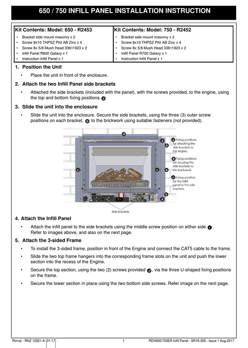
Rinnai 650 User manual

Rinnai

Rinnai 650 User manual

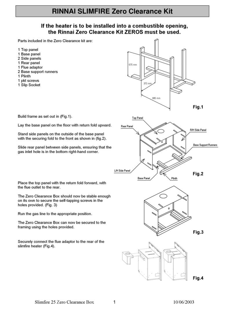
Rinnai Slimfire Zero Clearance Box User manual

Rinnai

Rinnai Slimfire Zero Clearance Box User manual

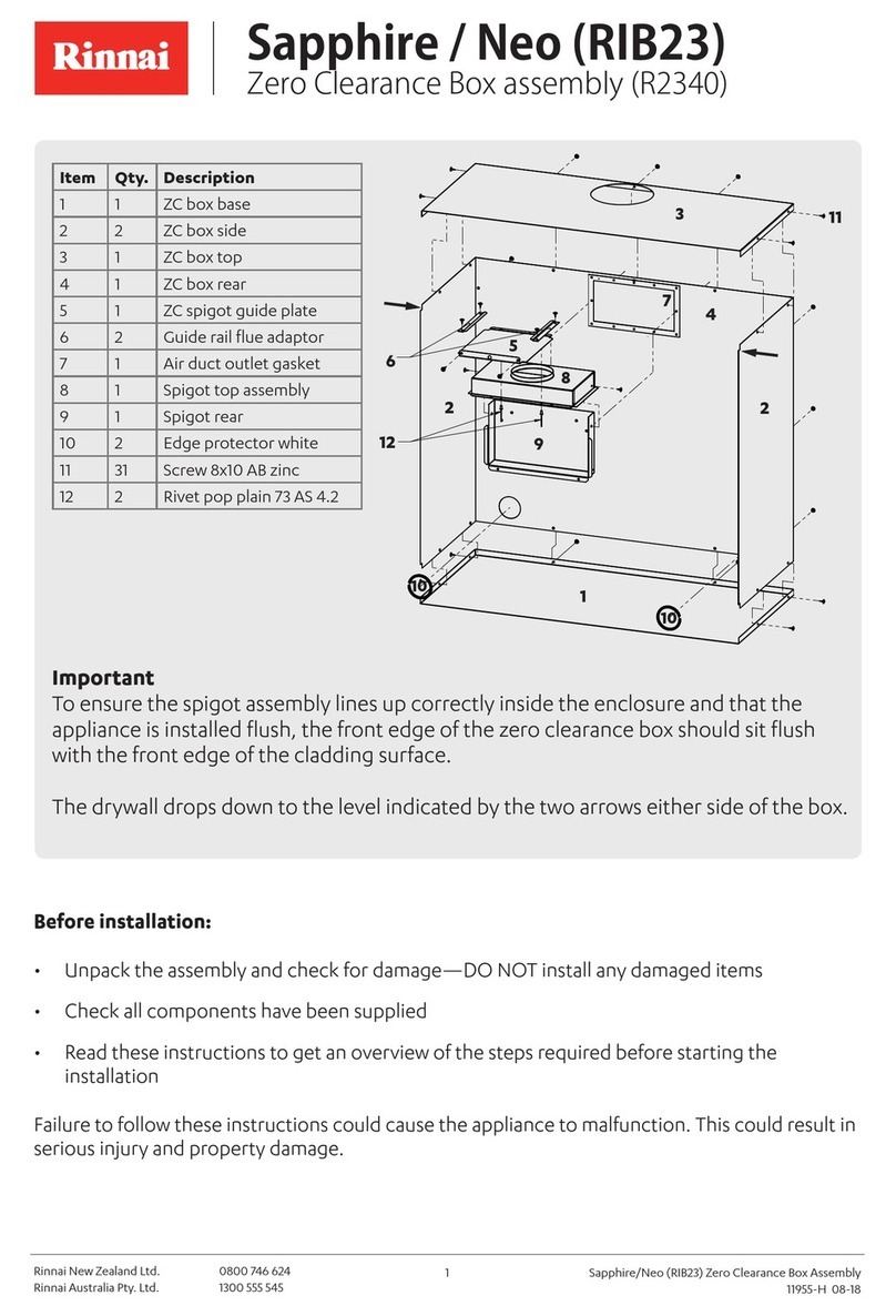
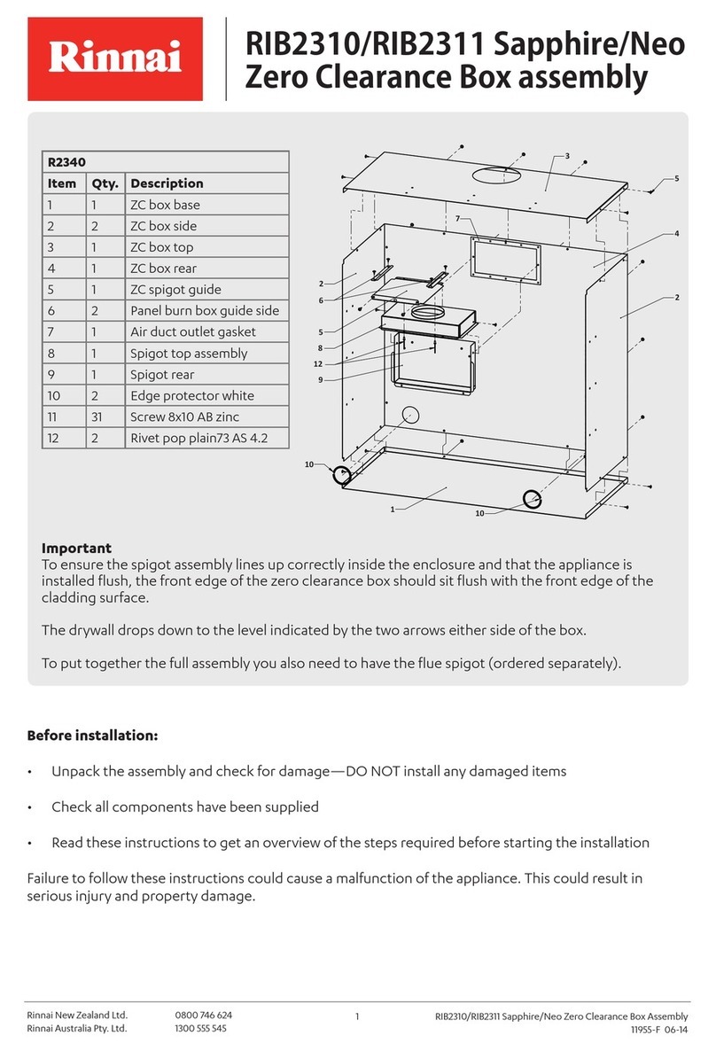
Rinnai Sapphire/Neo User manual

Rinnai

Rinnai Sapphire/Neo User manual

Popular Fireplace Accessories manuals by other brands

Valor L2 1700K quick start guide

Valor

Valor L2 1700K quick start guide

Exodraft Xzense manual

Exodraft

Exodraft Xzense manual

Whalen Ruso MNFP62BF23-6 manual

Whalen

Whalen Ruso MNFP62BF23-6 manual

Woodstock Soapstone Fireview 201 manual

Woodstock Soapstone

Woodstock Soapstone Fireview 201 manual

EdilKamin SERBATOIO 250 Installation, use and maintenance

EdilKamin

EdilKamin SERBATOIO 250 Installation, use and maintenance

Bronpi KIT-1 instructions

Bronpi

Bronpi KIT-1 instructions

Town & Country Fireplaces 22150051 instructions
Town & Country Fireplaces

Town & Country Fireplaces 22150051 instructions

Travis Industries 33 DVI installation instructions
Travis Industries

Travis Industries 33 DVI installation instructions

Lopi Hearthview 864 user manual

Lopi

Lopi Hearthview 864 user manual

Lennox Hearth Products LENNOX MPE-33R installation instructions

Lennox Hearth Products

Lennox Hearth Products LENNOX MPE-33R installation instructions

Dimplex DFP6776C install guide

Dimplex

Dimplex DFP6776C install guide

Napoleon W175-0689 instruction manual

Napoleon

Napoleon W175-0689 instruction manual

Travis Industries 95400424 installation instructions

Travis Industries

Travis Industries 95400424 installation instructions

Osburn ZERO CLEARANCE KIT installation instructions

Osburn

Osburn ZERO CLEARANCE KIT installation instructions

Majestic QUARTZPLA36IN installation instructions

Majestic

Majestic QUARTZPLA36IN installation instructions

Napoleon DBPO36 installation instructions

Napoleon

Napoleon DBPO36 installation instructions

Dimplex SMP-130-E install guide

Dimplex

Dimplex SMP-130-E install guide

Empire Comfort Systems LS50TINF installation instructions

Empire Comfort Systems

Empire Comfort Systems LS50TINF installation instructions

manuals.online logo
manuals.online logoBrands
  • About & Mission
  • Contact us
  • Privacy Policy
  • Terms and Conditions

Copyright 2025 Manuals.Online. All Rights Reserved.