DP DRV Series User manual

Submersible sewage pumps
Installation and operating instructions
series: DRV / DRK / DRS / DRSK

2
Table of Contents
1 Manual introduction
1.1 Preface................................................................................................................................................... 3
1.2 Icons and symbols ................................................................................................................................. 3
1.3 Identification, service and technical support .......................................................................................... 3
1.4 Terms of warranty .................................................................................................................................. 4
1.5 Supplementary documentation .............................................................................................................. 4
2 Safety and environment
2.1 General .................................................................................................................................................. 5
2.2 Users...................................................................................................................................................... 5
2.3 Safety provisions.................................................................................................................................... 5
2.4 Safety precautions ................................................................................................................................. 6
2.5 Environmental aspects........................................................................................................................... 6
3 Introduction
3.1 General .................................................................................................................................................. 7
3.2 Intended use .......................................................................................................................................... 7
3.3 Working range........................................................................................................................................ 7
3.4 Operation ............................................................................................................................................... 8
3.5 Operation of the automatic level regulation A-series ............................................................................. 8
4 Transportation
4.1 Transport.............................................................................................................................................. 10
4.2 Storage................................................................................................................................................. 10
5 Installation
5.1 Mechanical installation..........................................................................................................................11
5.2 Electrical installation .............................................................................................................................11
5.3 Commissioning .................................................................................................................................... 12
6 Operation
6.1 Operation ............................................................................................................................................. 13
7 Maintenance
7.1 Maintenance ........................................................................................................................................ 14
7.2 Taking out of operation for a long interval ............................................................................................ 15
8 Failures
8.1 Failure table ......................................................................................................................................... 16
9 Annexes
9.1 Technical specifications ....................................................................................................................... 18
9.2 Electrical connections .......................................................................................................................... 20
9.3 Declaration of conformity (IIA) ............................................................................................................. 21

3
1 Manual introduction
1.1 Preface
The manual contains important information for
reliable, proper and efficient operation. Compliance
with the operating instructions is of vital importance to
ensure reliability and a long service life of the product
and to avoid any risks.
The first chapters contain information about this
manual and safety in general. The following chapters
provide information about normal use, installation,
maintenance and repairs of the product. The annexes
contain the technical data, the parts drawings and the
declaration(s) of conformity.
•Make yourself familiar with the content.
•Accurately follow the directions and instructions.
•Never change the sequence of the operations to
be carried out.
•Keep this manual or a copy of it together with the
logbook in fixed place near the product, which
can be accessed by all personnel.
1.2 Icons and symbols
In this manual and in all accompanying
documentation the following icons and symbols are
used.
WARNING
Danger of electric tension. Safety sign
according to IEC 417 - 5036
WARNING
Operations or procedures, if carried out
without caution, may cause personal
injury or damage to the product.
General hazard sign according to ISO
7000-0434
ATTENTION
Is used to introduce safety instructions
whose non-observance may lead to
damage to the product and its
functions.
ENVIRONMENTAL INSTRUCTION
Remarks with respect to the
environment.
1.3 Identification, service and
technical support
You can identify the pump by the identification sticker
that is found on the pump.
Indication Meaning
DRV / DRK / DRS / DRSK Pump type
kPa Nominal pressure
l/sec Nominal capacity
RPM Nominal speed
V Nominal voltage
kW Motor power
A Nominal current
No. Serial number

4
The following address data are available for service
and technical support:
1.4 Terms of warranty
The warranty period is settled by terms of your
contract or at least by the general terms and
conditions of sales.
ATTENTION
Modifications or alterations of the
product supplied are only permitted
after consultation with the
manufacturer. Original spare parts and
accessories authorized by the
manufacturer ensure safety. The use of
other parts can invalidate any liability of
the manufacturer for consequential
damage.
ATTENTION
The warranty relating to the operating
reliability and safety of the product
supplied is only valid if the product is
used in accordance with its designated
use as described in the following
sections of this manual. The limits
stated in the data sheet must not be
exceeded under any circumstances.
The warranty becomes invalid if one or more of the
points below occur.
•The buyer makes modifications himself.
•The buyer carries out repairs himself or has
these carried out by a third party.
•The product has been handled or maintained
improperly.
•The product has non original DP-Pumps spare
parts fitted.
DP-Pumps remedies defects under warranty if the
points below are observed.
•Defects are caused by flaws in the design, the
materials or the production.
•The defect has been reported within the
warranty period.
Other terms of warranty have been included in the
general terms of delivery, which are available upon
request.
1.5 Supplementary
documentation
As well as this manual, the documentation given
below is also available:
DP-Pumps
Kalkovenweg 13
2401 LJ Alphen a/d Rijn
The Netherlands
Tel: +31 172 488325
Fax: +31 172 468930
Internet: www.dp-pumps.com
E-mail: dp@dp-pumps.com
Document Date/version Code
General terms of delivery 10-1998 119 / 1998
Documentation 11- 2005 97004429

5
2 Safety and environment
2.1 General
This DP-Pumps product has been developed in
accordance with state-of-the-art technology; it is
manufactured with utmost care and subject to
continuous quality control.
DP-Pumps does not accept any liability for damage
and injury caused by not observing the directions and
instructions in this manual. This also applies in cases
of carelessness during the installation procedure, use
and maintenance of the product.
Non-compliance with safety instructions can
jeopardize the safety of personnel, the environment
and the product itself. Non-compliance with these
safety instructions will also lead to forfeiture of any
and all rights to claims for damages.
In particular, non-compliance can, for example, result
in:
•failure of important pump/system functions,
•failure of prescribed maintenance and servicing
practices,
•injury to persons by electrical, mechanical and
chemical effects,
•hazard of the environment due to leakage of
hazardous substances,
•explosions.
Depending on specific activities, extra safety
measures may be required. Contact DP-Pumps if
during use a potential danger arises.
ATTENTION
The owner of the product is responsible
for compliance with the local safety
regulations and internal company
guidelines.
ATTENTION
Not only must the general safety
instructions laid down in this chapter
on "Safety" be complied with, but also
the safety instructions outlined under
specific headings
2.2 Users
All personnel involved in the operation, maintenance,
inspection and installation of the product must be fully
qualified to carry out the work involved.
Personnel responsibilities, competence and
supervision must be clearly defined by the operator. If
the personnel in question is not already in possession
of the required know-how, appropriate training and
instruction must be provided. If required, the operator
may commission the manufacturer / supplier to take
care of such training. In addition, the operator is
responsible for ensuring that the contents of the
operating instructions are fully understood by the
responsible personnel.
2.3 Safety provisions
The product has been designed with the greatest
possible care. Original parts and accessories meet
the safety regulations. Modifications in the
construction or the use of non-original parts may lead
to a safety risk.
ATTENTION
Make sure that the product operates
within its working range. Only then the
product performance is guaranteed.
2.3.1 Labels on the product
The icons, warnings and instructions applied to the
product are part of the safety provisions. The labels
may not be removed or covered. Labels must remain
legible during the entire life of the product. Replace
immediately damaged labels.

6
2.4 Safety precautions
2.4.1 During normal use
•Contact the local electricity company for
questions about the power supply.
•Shield parts that can become hot in such a way,
that direct contact is impossible.
•When applicable, always place undeformed
coupling protection plates to protect the
coupling, before putting the pump into use. Make
sure that the coupling protection plates are
never in contact with the running coupling.
•Always close the switch box.
2.4.2 During installation, maintenance and
repair
Only authorised personnel may install, maintain and
inspect the product and repair electrical components.
Observe the local safety regulations.
WARNING
Always disconnect the energy supply to
the product first, before installation,
maintenance and repairs. Secure this
disconnection.
WARNING
Surfaces of a pump can be hot, after
continuous operation.
WARNING
Make sure that no one can be near
rotating components when starting a
pump.
WARNING
Handle a pump with dangerous liquids
with the utmost care. Avoid danger for
persons or the environment when
repairing leakages, draining liquids and
venting. It is strongly recommended to
place a relief barge under the pump.
WARNING
Immediately following completion of
the work, all safety-relevant and
protective devices must be re-installed
and / or re-activated.
WARNING
Please observe all instructions set out
in the chapter on "Commissioning/
Start-up" before returning the product
to service.
2.5 Environmental aspects
2.5.1 General
The products of DP-Pumps are designed to function
in an environmentally friendly way during their entire
life. Therefore, when applicable, always use
biodegradable lubricants for maintenance.
ENVIRONMENTAL INSTRUCTION
Always act according to the laws, by-
laws regulations and instructions with
respect to health, safety and the
environment.
2.5.2 Dismantling
Dismantle the product and dispose of it in an
environmentally friendly way. The owner is
responsible for this.
ENVIRONMENTAL INSTRUCTION
Ask at the local government about the
re-use or the environmentally friendly
processing of discarded materials.

7
3 Introduction
3.1 General
Submersible sewage pumps of the type DRV /
DRK / DRS / DRSK
Submersible sewage pumps of the type DRV / DRK /
DRS / DRSK are produced by DP-Pumps.
3.2 Intended use
The submersible pumps of the DRV / DRK / DRS /
DRSK series are suitable for pumping the substances
given below within the specified working range (see
“Working range").
•Water with faeces.
•Water with solid or fibrous constituents.
•Sludge or thicker liquids.
•Clean or lightly contaminated wastewater.
•Rainwater.
Any other or further use of the pump is not in
conformity with its intended use. DP-Pumps does not
accept any liability for any damage or injury that
results from this. The pump is produced in
accordance with the current standards and
guidelines. Use the pump only in a perfect technical
state, in conformance with the intended use
described below.
The Intended use as laid down in EN 12100-1 is the
use for which the technical product is intended
according to the specifications of the manufacturer.
The use of the product has been described in the
sales brochure and in the user manual. Always
observe the instructions given in the user manual.
When in doubt the product must be used as becomes
evident from its construction, version and function.
3.3 Working range
The working range of the submersible sewage pumps
can be summarised as follows:
Table 1: Specification of the working range
Table 2: Specific applications
Submersible sew-
age pump type
DRV DRK DRS DRSK
Liquid temperature
[°C]
•maximum 40 40 40 55
•minimum 1 1 1 1
Free passage [mm] 35 - 135 35 - 135 none 65 - 76
frequency [Hz] 30 - 50 30 - 50 30 - 50 30 -50
Type Application area
DRV Pumping heavily contaminated liq-
uids with solid and long staple con-
stituents such as untreated sewage
DRK Pumping lightly contaminated liq-
uids with solid and long staple con-
stituents
DRS Shredding and pumping liquids
with faeces and household waste-
water.
DRSK Pumping heavily contaminated liq-
uids with solid and long staple con-
stituents such as untreated sewage

8
3.4 Operation
The liquid is suctioned with a minimum supply
pressure on the suction side (A). The pump increases
the pressure. The liquid leaves the pump on the
delivery side (B).
A Suction side
B Delivery side
Submersible sewage pumps that have been
equipped with a build-in floater are automatically
switched on and off when reaching a high or low
liquid level respectively.
Solid constituents from the wastewater can pass the
impeller without problems due to the large free
passage opening of the submersible sewage pump.
The performance (capacity and head) of the pump is
determined by the motor power and the impeller type
of the installed submersible sewage pump.
Table 3: Submersible sewage pump version
3.5 Operation of the automatic
level regulation A-series
A-Series switching levels
3.5.1 One pump operation
The pump will randomly start at level S2 or S3 and
will switch itself off at the lowest off switching level
after the initiation phase. The times between the
levels S3, S2 and S1 and the lowest off switching
level are saved in the system memory.
The pump will start at level S2 or S3 during the
following 7 switching cycles. The choice is random.
The off switching moment will be calculated based on
the number of saved starts between the levels S3, S2
and S1 and the lowest off switching level. When the
pump has completed 7 switching cycles based on the
previous calculation, the time measurements and the
detection of the lowest off switching level is repeated
and saved and the newly calculated pumping time is
assigned to the pump. The time will be saved that is
required to reach level S3, S2 or S1 when wastewater
continues to flow in. The period during which the
pump is operational will be adjusted to this.
When the pump has not been operational for a period
of 24 hours, the pump will start until the lowest off
switching level is detected. The test run will be
automatically activated after every 24 hour period
when the water level has not demanded a pump start.
Type DRV DRK DRS DRSK
Impeller
type
Vortex
impeller
Channel
impeller
Shredder
(hardened
stainless
steel)
Non-
clogging
impeller
Safety class IP68
Insulation
class
F
Sealing Double mechanical seal with intermediate oil
chamber
A
B
2666/12092005
20050998

9
The pump sends coded impulses to report failures.
Special modules can decode these impulses and can
specify the failures through failure lights or optical
contacts.
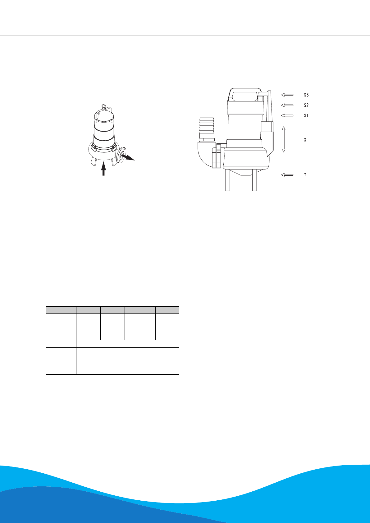
3.5.2 Two pump operation
The different operational phases of the pump are
combined through an algorithm in two pump
operation which enables the pumps to recognise
each other. The ratio of pumping times between
levels S3, S2, S1 and the lowest off switching level
are saved individually for each of the two pumps. The
pumping time that is calculated is assigned to the
following 7 pump cycles. Volume detection is
performed independently after every eighth pump
cycle.
The pumps can be operational simultaneously or in
sequence because the choice for starting one of the
pumps is random at level S2 or S3. When the water
level drops to below level S1 in relation to a pump that
is not operational, this pump will conclude that a
partner pump is available. The information about
there being a partner pump will be saved in the
memory of both pumps. The pump that has just been
operational, will save level S3 as the on switching
level. The pump that was not operational and which
detected the water level has dropped up to below
level S1, will now save level S2 as the on switching
level.
The two pumps will switch on in turns to on switching
level S2 when the water level drops to below level S1
of the pump that was currently not operational. When
the pumps have detected that there is a partner
pump, they will be switched on in turns when level S2
has been reached.
When sewage continues to flow into the pump sump,
the time is saved that is required to reach level S2
and level S1. The pumping time will be corrected
based on this. The same correction method can be
used for volume detection to compensate in changes
in the required pumping time when a partner pump is
available.
When one pump cannot supply sufficient pumping
capacity to drain away the incoming wastewater, the
second pump will be switched on when level S3 is
reached. You can determine when the pumps should
be switched off depending on the speed at which the
pump sump fills up and the time that is required for it
to be pumped and emptied. This can be determined
by both calculation and detection of the lowest off
switching level.
When one or both pumps have not been in operation
for a period of 24 hours, the pump or pumps will start
until the lowest off switching level has been detected.
The test run will be automatically activated after every
24 hour period when the water level has not
demanded a pump start.
3.5.3 Points of special interest
It is very important that the vent hole of the pump
housing is opened because the pump continues
running until the pump suctions air every eighth cycle.
ATTENTION
When installing a pump with an
automatic level regulation, the pump
must be at least 20 cm from the wall.
ATTENTION
The pump must be installed in such a
way that the inflow of the drain can
never reach the sensors for the level
regulation.
When a pump with automatic level regulation detects
that the water level is still above level S3 after 16
seconds, the pump will stop for a period of 3 seconds
will give a coded report for high water. A pump with
automatic level regulation must, therefore, only be
used in a drain.

10
4 Transportation
4.1 Transport
WARNING
Lift the pump, if necessary using a hoist
and suitable slings. Attach the slings to
the hoisting eyes on the packaging,
where present.
WARNING
The pump must be hoisted according to
the current hoist guidelines. Only
qualified personnel are allowed to hoist
the pump.
1. Transport the pump in the position as indicated
on the pallet or packaging.
2. Make sure the pump is stable.
3. Observe the instructions on the packaging (if
present).
4.2 Storage
4.2.1 Storage preparation
1. Spray clean the pump and the impeller in the
pump housing well using clean water.
2. Store the pump in a dry and frost-proof location.
4.2.2 Inspection during storage
1. Turn the impeller every three months. This will
prevent sticking of the running seals.
2. Have the pump inspected before putting it into
operation again after a storage period of 6
months or longer.

11
5 Installation
5.1 Mechanical installation
WARNING
Remove all cables and hoisting chains
from the pump sump. Prevent thus that
they can be sucked and damaged by
the pump.
WARNING
Never allow the pump to drop from the
feeder cable or delivery pipe. Use a
chain or a sufficiently strong cable that
is attached to the grip of the pump.
WARNING
Do not use the pump in locations where
there is freezing danger.
•Take the pump out of the packaging and check
for any transportation damage.
•Check whether the delivery is complete based
on the included Production Order Combination
List. Contact DP-Pumps if the delivery is
damaged and/or incomplete.
•Position and assemble the pump system on a
suitable surface or suspend the pump using the
grip.
•Position the pump on a paved surface when
there is mud and sand.
•Check whether the pump impeller can turn
freely.
•Make sure that the distance between the bottom
and the supply (A) is at least the same as the
free passage, see the technical information.
•Assemble, if required, a non-return valve in the
delivery pipe to prevent liquid flowing back. The
swing check valve must be installed at least 2 m
from the pump for the “A" version pump.
•Assemble (if possible) a globe valve on the
delivery side.
•Install the highest point of the delivery pipe
above the drain pipes of the street (ground level)
to make sure that a drain return flow is not
possible.
5.2 Electrical installation
WARNING
Only authorised personnel are allowed
to make electrical connections to the
motor in accordance with local
regulations.
Electrical connections:
•Make sure that the motor specifications
correspond with the power supply to which the
pump motor is connected. Consult "Electrical
diagrams" in the annexes for the correct
connection diagram.
•Connect the motor using a motor safety switch.
The setting must be the same as the motor
amperage as listed on the identification label in
relation to a direct start (DOL; Direct On Line).
•Connect the pump in accordance with the
electrical diagram that can be found in the
junction box.
•When the pump is being connected through a
frequency transformer, the motor must be
provided with a suitable “shielded” cable
specially for this situation. The temperature
protection in the pump must also be connected
to the frequency transformer. Range 30-50 Hz

12
5.3 Commissioning
WARNING
The pump must not be switched on
when it does not contain any liquid.
The direction of rotation of the pump is clockwise
seen from the top of the pump (A). The reactive force
will cause a shock movement in the opposite direction
(B) when started up.
ATTENTION
In case of a 3-phase motor the rotating
direction can be changed by
exchanging two of the three phase
wires.
ATTENTION
You are allowed to reduce the
submersible level up to the set point
specified in 9.1 Technical specifications
when operation is intermittent.
ATTENTION
The pump must be completely
submersed when operation is
continuous.
Check whether the submersible sewage pump
switches on and off at the correct liquid levels when
commissioning. Fill the drain up to the on switching
level of the pump. Use the liquid to be pumped or
clean water.
1 Check whether the pump switches on
automatically.
2 Check whether the pump switches off
automatically when reaching the off switching
level.
3 Check whether liquid is not returned from the
delivery pipe in the drain.
ATTENTION
Drill a small hole for venting at the
highest point of the pipe system (just
before the swing check valve) should
air remain enclosed in the pump
housing. Provide the hole with a
stainless steel nipple to ensure it
cannot become rusted up. Remember
that liquid can squirt from the drilled
hole.
ATTENTION
The DRV6/8 and DRS3 have been fitted
with a special bolt that can be removed
when there are problems with air
staying in the pump housing. The bolt
can be found on the other side of the
delivery connection under the motor
cable inlet.
A
B

13
6 Operation
6.1 Operation
Pump
type
operation
xxx-W pump with earthed plug
xxx-WS switch on/off the pump automatically through
the float switch
xxx-WA pump automatically on/off through the inter-
nal level regulating system
xxx-S MANUAL - switch on the pump manually
0 - pump off
Auto - pump automatically on/off through the
float switch
xxx- pump with free cable end
xxx- pump with junction box, will switch on/off
automatically through the internal level regu-
lating system

14
7 Maintenance
7.1 Maintenance
WARNING
Disconnect the power supply to the
system before performing maintenance
work, and protect this disconnection.
WARNING
Remember that the motor can be hot
when it has just been switched off.
WARNING
Clean the pump with clean water before
carrying out maintenance work.
WARNING
Ensure that the guide clamp does not
become jammed on the guide bars if a
tackle is being used to remove the
pump from the drain.
Regular maintenance will promote the permanent
good operation of the installation. DP-Pumps has its
own maintenance department with specialised
engineers. A draft maintenance contract is available
upon request.
7.1.1 Maintenance schedule
The pump must be checked every 4000 operational
hours or at least once a year. We recommend
carrying out an overhaul every 5 years.
The maintenance interval should be adjusted when
operational conditions are heavier.
The bearings of the pump have been lubricated
for life and, therefore, do not require maintenance.
7.1.2 Oil chamber check
ATTENTION
All pumps have a closed, maintenance-
free system. Only the pumps of the DRK
type or in the HT or E version have a
checking option.
Check the oil chamber for any leaks of the seals.
1 Remove the inspection plug of the pump
housing.
2 Position the pump in a horizontal position with
the inspection opening downwards.
Any liquid that may be present in the pump housing
can now low out through the opening. Check the
composition of the liquid to discover any leaks.
Liquid Cause
Clear oil No leaks.
Lightly coloured oil A small quantity of moisture is
allowed.
Water/oil Not allowed; the seal or pump is
leaking1
1. Contact the supplier.
Overpressure Not allowed; seal or motor is
leaking1

15
7.1.3 Checking and cleaning the shredder
device (DRS)
Disassemble the shredder device and suction cover
and clean and perform an inspection. Next, install the
shredder device according to:
1 Position the impeller with the cutter head on the
pump shaft.
2 Secure the impeller.
3 Turn back the adjusting screws of the suction
cover up to the flange to ensure they no longer
protrude.
4 Install the suction cover in the pump housing.
5 Press the suction cover until the flange is on the
impeller everywhere.
6 Tighten the adjusting screws until the impeller is
just turning freely (gap = 0.3mm +/- 0.1mm).
7 Tighten the fastening bolts tightly.
ATTENTION
Again check whether the impeller can
turn freely.
7.2 Taking out of operation for a
long interval
Turn the impeller every three months. This will
prevent seals from sticking.
Protect the pump against freezing if there is a risk of
frost. Proceed as follows:
1. Close all globe valves.
2. Remove the pump from the drain.
3. Make sure the pump is cleaned correctly by
spraying with a powerful water jet.
4. Store the pump in a dry and frost-proof location.

16
8Failures
8.1 Failure table
WARNING
Take the general safety measures for the installation, maintenance and repair into
consideration.
Problem Possible cause Possible solution Checkpoints
The pump will not start No voltage on the termi-
nal clamps
Check the power supply •Circuit
•Main switch
•Hand-0-Aut switch
•Fuses
Check the motor safety
relay
•Earth leakage switch
•Protective relay
•Motor temperature
•Water feeler (option)
Check the start signal •Medium level
•Level switching
•Start-stop change
•Switch box
Motor failures Check the motor •Insulation test
•Phase resistance
The pump does not stop No stop signal Check level switching •Level switching
•Switch box
Air in the pump housing Temporarily remove the
pump from the coupling
Pump switching level
The pump starts and stops
quickly after each other
Incorrect start/stop signal Check the level switches •Level switching
•Adjusting switches
Power supply is unstable Check the power supply •Circuit
•Undervoltage
•3-phase available?
•Adjustment of the
motor protection
•Fuses
Pump current is too high Current failure Check the power supply •Fuses
•Undervoltage
Pump failure Check the pump •Impeller blockage
•Viscosity of the
medium
The direction of rotation is
incorrect
Reverse the direction of
rotation
The capacity is too high Increase the counterpres-
sure

17
Too little or no pump
capacity
Blockage or an air bubble
in the pump
Check the delivery pipe
and the pump
•Delivery pipe (block-
age)
•Globe valve (half or
fully closed)
•Inclusion of air
•Blockage (impeller)
•Check level switching
Incorrect direction of rota-
tion
Reverse the direction of
rotation
Direction of rotation
Pump failure Check the pump •Coupling (leaking)
•Impeller (has come
loose or is damaged)
•Impeller or pump
housing (blockage)
•Bearings damaged
Power supply is unstable Check the power supply •Switch box
•Fuses
•Undervoltage
High water alarm Too little pump capacity Check the delivery pipe •Delivery pipe (block-
age)
•Globe valve (half or
fully closed)
•Inclusion of air
Pump failure Check the pump •Impeller or pump
housing (blockage)
•Impeller (has come
loose or is damaged)
•Bearings damaged
Current failure Check the power supply •Fuses
•Undervoltage
Motor failures Check the motor •Junction box
•Insulation test
Problem Possible cause Possible solution Checkpoints

18
9 Annexes
9.1 Technical specifications
pump type P
[kW]
Inom
[A]
Umotor
[V]
n
[min-1]
tempera-
ture protec-
tion
cable type
[n x mm2]
H1
[mm]
Connec-
tion
[DN]
Free pas-
sage
[mm]
Mass
[kg]
DRV66-2 100 0.55 2.3 3*400 2850 naw 4*1 160 50 45 22
DRV66-2A 100 0.55 2.3 3*400 2850 naw 4*1 65 50 45 22
DRV66-2W(S) 100 0.55 5 1*230 2850 clixon 3*1 160 50 45 22
DRV66-2WA 100 0.55 5 1*230 2850 clixon 3*1 65 50 45 22
DRV68-2 110 0.75 2.8 3*400 2850 naw 4*1 160 50 45 22
DRV68-2A 110 0.75 2.8 3*400 2850 naw 4*1 65 50 45 22
DRV68-2W(S) 110 0.75 6 1*230 2850 clixon 3*1 160 50 45 22
DRV68-2WA 110 0.75 6 1*230 2850 clixon 3*1 65 50 45 22
DRV611-2 120 1.1 3 3*400 2850 naw 4*1 160 50 43 22
DRV611-2A 120 1.1 3 3*400 2850 naw 4*1 65 50 43 22
DRV611-2W(S) 120 1.1 8.2 1*230 2850 clixon 3*1 160 50 43 22
DRV611-2WA 120 1.1 8.2 1*230 2850 clixon 3*1 65 50 43 22
DRV611-2W(S) 130 1.1 8.2 1*230 2850 clixon 3*1 160 50 41 22
DRV611-2WA 130 1.1 8.2 1*230 2850 clixon 3*1 65 50 41 22
DRV615-2 130 1.5 3.5 3*400 2850 naw 4*1 160 50 41 22
DRV615-2A 130 1.5 3.5 3*400 2850 naw 4*1 65 50 41 22
DRV88-2 110 0.75 2.8 3*400 2850 naw 4*1 170 65 60 25
DRV88-2A 110 0.75 2.8 3*400 2850 naw 4*1 70 65 60 25
DRV88-2W(S) 110 0.75 6 1*230 2850 clixon 3*1 170 65 60 25
DRV88-2WA 110 0.75 6 1*230 2850 clixon 3*1 70 65 60 25
DRV811-2 120 1.1 3 3*400 2850 naw 4*1 170 65 58 25
DRV811-2A 120 1.1 3 3*400 2850 naw 4*1 70 65 58 25
DRV811-2W(S) 120 1.1 8.2 1*230 2850 clixon 3*1 170 65 58 25
DRV811-2WA 120 1.1 8.2 1*230 2850 clixon 3*1 70 65 58 25

19
DRV811-2W(S) 130 1.1 8.2 1*230 2850 clixon 3*1 170 65 56 25
DRV811-2WA 130 1.1 8.2 1*230 2850 clixon 3*1 70 65 56 25
DRV815-2 130 1.5 3.5 3*400 2850 naw 4*1 170 65 56 25
DRV815-2A 130 1.5 3.5 3*400 2850 naw 4*1 70 65 56 25
DRV913-2 90(107) 1.3 3.56 3*400 2850 bi-metal 7*1.5 207 50 40 41
DRV919-2 120 1.9 4.5 3*400 2850 bi-metal 7*1.5 207 50 40 42
DRV923-2 130 2.3 5.1 3*400 2850 bi-metal 7*1.5 207 50 40 42
DRV1131-2 130(140) 3.1 7 3*400 2850 bi-metal 7*1.5 203 50 40 52
DRV1142-2 150 4.2 8.8 3*400 2850 bi-metal 7*1.5 203 50 40 53
DRV128-4 112
(125/135/145/155)
0.8 2.75 3*400 1450 bi-metal 7*1.5 253 65 65 49
DRV1213-4 165(175) 1.3 3.54 3*400 1450 bi-metal 7*1.5 253 65 65 50
DRV1218-4 185(195) 1.8 4.25 3*400 1450 bi-metal 7*1.5 253 65 65 51
DRV1331-2 120(128) 3.1 7 3*400 2850 bi-metal 7*1.5 248 65 65 58
DRV1331-2 136 3.1 7 3*400 2850 bi-metal 7*1.5 248 65 65 59
DRV1342-2 146 4.2 8.8 3*400 2850 bi-metal 7*1.5 248 65 65 59
DRV1342-2 152 4.2 8.8 3*400 2850 bi-metal 7*1.5 248 65 65 60
DRV2419-4 120
(135/150)
1.9 5.87 3*400 1450 bi-metal 7*1.5 249 80 76 63
DRV2426-4 165 2.6 6.5 3*400 1450 bi-metal 7*1.5 249 80 76 64
DRV2437-4 180(195) 3.7 8.4 3*400 1450 bi-metal 7*1.5 249 80 76 65
DRV2719-4 120(135) 1.9 5.87 3*400 1450 bi-metal 7*1.5 277 100 100 64
DRV2726-4 150 2.6 6.5 3*400 1450 bi-metal 7*1.5 277 100 100 64
DRV2737-4 165 3.7 8.4 3*400 1450 bi-metal 7*1.5 277 100 100 65
DRV2737-4 180 3.7 8.4 3*400 1450 bi-metal 7*1.5 277 100 100 66
DRV2737-4 195 3.7 8.4 3*400 1450 bi-metal 7*1.5 277 100 100 67
DRK2385-2 182 8.5 16.7 400/692 2905 bi-metal 12*1.5 320 80 42 151
DRK2385-2 196 8.5 16.7 400/692 2905 bi-metal 12*1.5 320 80 42 151
DRK4155-4 202(220) 5.5 12.1 400/692 1430 bi-metal 12*1.5 380 100 90 141
DRK4175-4 245 7.5 15.8 400/692 1440 bi-metal 12*1.5 380 100 90 155
DRK87118-4 254 11.8 23.5 400/692 1465 bi-metal 12*1.5 455 150 110 146
DRK87160-4 275 16 33 400/692 1465 bi-metal 7*4+5*1.5 455 150 110 256
DRK87210-4 295 21 40.5 400/692 1435 bi-metal 7*4+5*1.5 455 150 110 325
DRK87270-4 305 27 55 400/692 1455 bi-metal 7*6+5*1.5 455 150 110 343
DRK107118-4
235(250)
11.8 23.5 400/692 1465 bi-metal 12*1.5 455 150 76 146
DRK107160-4 265 16 33 400/692 1465 bi-metal 7*4+5*1.5 455 150 76 256
DRK107210-4 280 21 40.5 400/692 1435 bi-metal 7*4+5*1.5 455 150 76 325
DRK107270-4 295 27 55 400/692 1455 bi-metal 7*6+5*1.5 455 150 76 343
DRK145130-6
319(351)
13 27.5 400/692 965 bi-metal 7*4+5*1.5 750 200 121 480
DRK145180-6 373 18 35.5 400/692 955 bi-metal 7*4+5*1.5 750 200 121 480
DRK145240-6 400 24 47 400/692 960 bi-metal 7*6+5*1.5 750 200 121 505
DRK178130-6 300 13 27.5 400/692 965 bi-metal 7*4+5*1.5 600 250 85 555
DRK178180-6 318 18 35.5 400/692 955 bi-metal 7*4+5*1.5 600 250 85 555
DRK178240-6 340 24 47 400/692 960 bi-metal 7*6+5*1.5 600 250 85 580
DRK178300-6 370 30 64 400/692 975 bi-metal 2*4*6+
12*1.5
600 250 85 710
DRK250100-8
332(355)
10 22.5 400/692 715 bi-metal 12*1.5 750 300 135 735
pump type P
[kW]
Inom
[A]
Umotor
[V]
n
[min-1]
tempera-
ture protec-
tion
cable type
[n x mm2]
H1
[mm]
Connec-
tion
[DN]
Free pas-
sage
[mm]
Mass
[kg]

20
9.2 Electrical connections
ATTENTION
The bi-metal switch (connection 21-22) of the pump is suitable for switching 250 V AC at 2 A. Do
not connect connection 20; do shield it.
Table 4: Cable coding
DRK250100-8 332 10 22.5 400/692 715 bi-metal 12*1.5 750 300 135 735
DRK250200-8 390 20 44 400/692 705 bi-metal 7*6+5*1.5 750 300 135 775
DRK250280-8 408 28 60 400/692 730 bi-metal 2*4*4+
12*1.5
750 300 135 900
DRS311-2W(S) 145 1.1 8.2 1*230 2850 clixon 4*1 160 50 7 26
DRS311-2WA 145 1.1 8.2 1*230 2850 clixon 4*1 84 50 7 26
DRS315-2 145 1.5 3.5 3*400 2850 naw 4*1 160 50 7 24
DRS315-2A 145 1.5 3.5 3*400 2850 naw 4*1 84 50 7 24
DRS413-2 120(140) 1.3 3.56 3*400 2850 bi-metal 7*1.5 207 50 6 39
DRS419-2 160 1.9 4.5 3*400 2850 bi-metal 7*1.5 207 50 6 39
DRS631-2 175 3.1 7 3*400 2850 bi-metal 7*1.5 203 50 6 54
DRS642-2 190 4.2 8.8 3*400 2850 bi-metal 7*1.5 203 50 6 54
DRSK 2119-4 154 1.9 5.9 3*400 1450 bi-metal 7*1.5 602 80 65 74
DRSK 2119-4 168 1.9 5.9 3*400 1450 bi-metal 7*1.5 602 80 65 74
DRSK 2119-4 180 1.9 5.9 3*400 1450 bi-metal 7*1.5 602 80 65 74
DRSK 2119-4 190 1.9 5.9 3*400 1450 bi-metal 7*1.5 602 80 65 75
DRSK 3126-4 195 2.6 6.5 3*400 1450 bi-metal 7*1.5 628 100 76 79
DRSK 3137-4 209 3.7 8.4 3*400 1450 bi-metal 7*1.5 628 100 76 79
DRSK 3137-4 220 3.7 8.4 3*400 1450 bi-metal 7*1.5 628 100 76 80
DRV 6/8 DRS 3 DRV 9/11/12/13/
24/27 DRS 4/6
DRSK 21 / 31
DRK
(n = 12)
DRK
(n = 1x7 + 1x5)
L1 U1 black 1 1 1
L2 V1 blue 2 2 2
L3 W1 brown 3 3 3
Dummy connection 20 4
Bi-metal 21 5 7 1
22 682
Earthing PE green/yellow green/yellow green/yellow green/yellow
L2’ UU2 4 4
L3’ UV2 5 5
L1’ UW2 6 6
PTC1
1. PTC and humidity sensor depends on the type of motor.
10 9 3
11 10 4
Humidity sensor19115
pump type P
[kW]
Inom
[A]
Umotor
[V]
n
[min-1]
tempera-
ture protec-
tion
cable type
[n x mm2]
H1
[mm]
Connec-
tion
[DN]
Free pas-
sage
[mm]
Mass
[kg]
This manual suits for next models
114
Table of contents
Other DP Water Pump manuals
Popular Water Pump manuals by other brands

Grundfos
Grundfos MAGNA3 25-100 (N) instructions

Aktobis AG
Aktobis AG WDH-KP40 manual

Shenchen
Shenchen V6-12L Series manual

Air Monitoring Solutions
Air Monitoring Solutions AMS16L Technical manual

Annovi Reverberi
Annovi Reverberi AR160LFP-C/C instruction manual

Viking pump
Viking pump 124E Series Technical & service manual

KSB
KSB Amarex KRT Installation & operating manual

AquaCare
AquaCare TKP Series instruction manual

AIRMAC
AIRMAC DBMX250 Maintenance manual

GORMAN-RUPP PUMPS
GORMAN-RUPP PUMPS PA Series Installation, operation and maintenance manual

PYD Electrobombas
PYD Electrobombas POOL Series Instruction manual and maintenance

MSW
MSW MSW-ETT-VAG-117 user manual