1
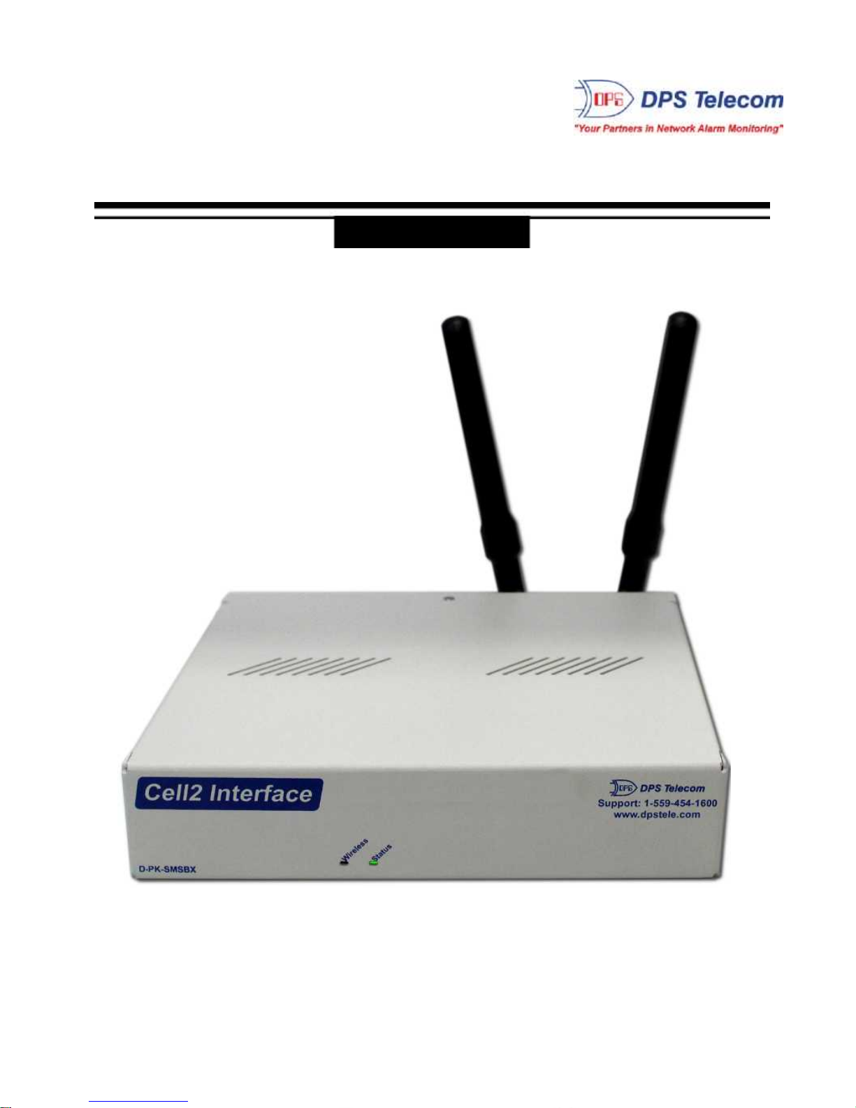
Cell2 Interface Overview
1
Receive alarms via GSM or CDMA with the Cell2 Interface.
Wireless alarms to your master station
The Cell2 Interface allows you to utilize wireless RTUs with your alarm master station without paying for an
expensive third-party data provider or opening a hole in your firewall to receive alarms on your master station.
Wireless RTUs used to create a lot of unwanted hassle. To send alarms to your master station, you had to pay
your cellular carrier or a third-party data provider for a static IP address. Then, you had to punch a hole in your
firewall to get that data back into your network - a security risk some IT departments simply weren't willing to take.
With the Cell2 Interface, you can now report alarms to your T/Mon or SNMP master station without paying your
cellular carrier for a static IP or creating a security breach. Alarms can be reported via SMS directly to your master
station.
How it Works
Rather than reporting alarms over IP, simply configure your wireless Cell2 to send SMS alarm information to the
Cell2 Interface. The Cell2 Interface then forwards the alarm information to T/Mon (or other SNMP manager) when
polled over LAN using DCPx protocol.
Reporting alarms via SMS rather than IP allows you to bypass the traditional hassles of wireless IP-based alarm
reporting. One Cell2 Interface can support alarms for up to 253 Cell2 Devices, allowing you to cheaply and easily
deploy wireless RTUs or establish a backup alarm-reporting path over wireless devices.
Upgraded Web Browser
The overhauled web interface boasts several time-saving new tools. You'll also notice the impressive speed boost.
Menus load nearly instantly and the entire interface is very responsive.