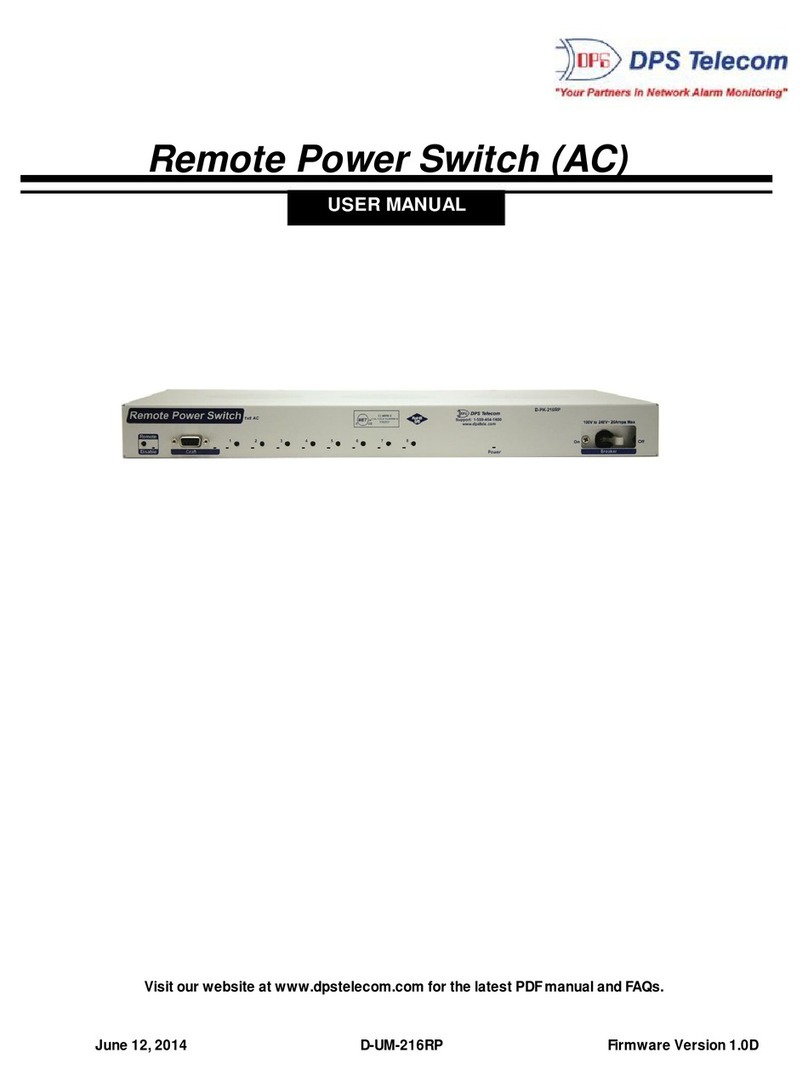
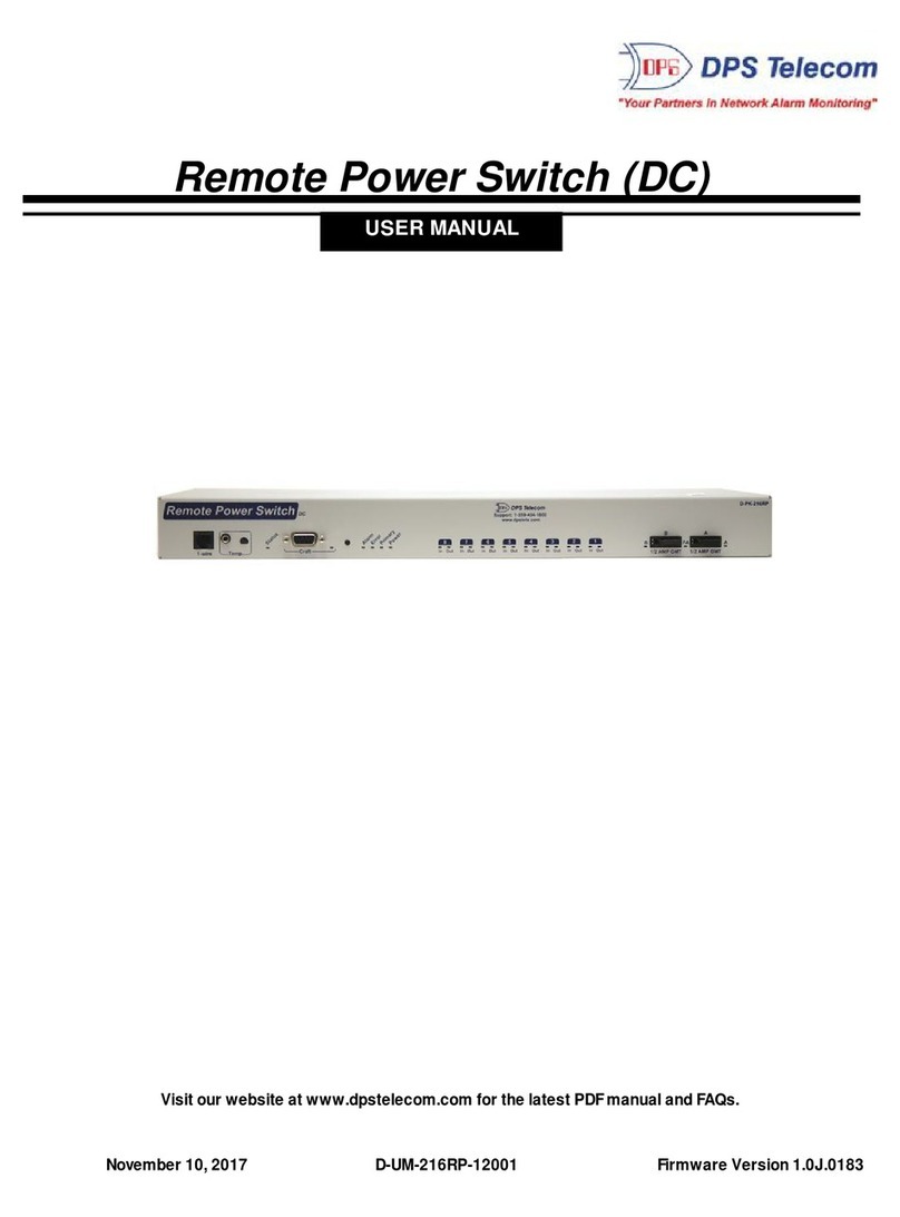
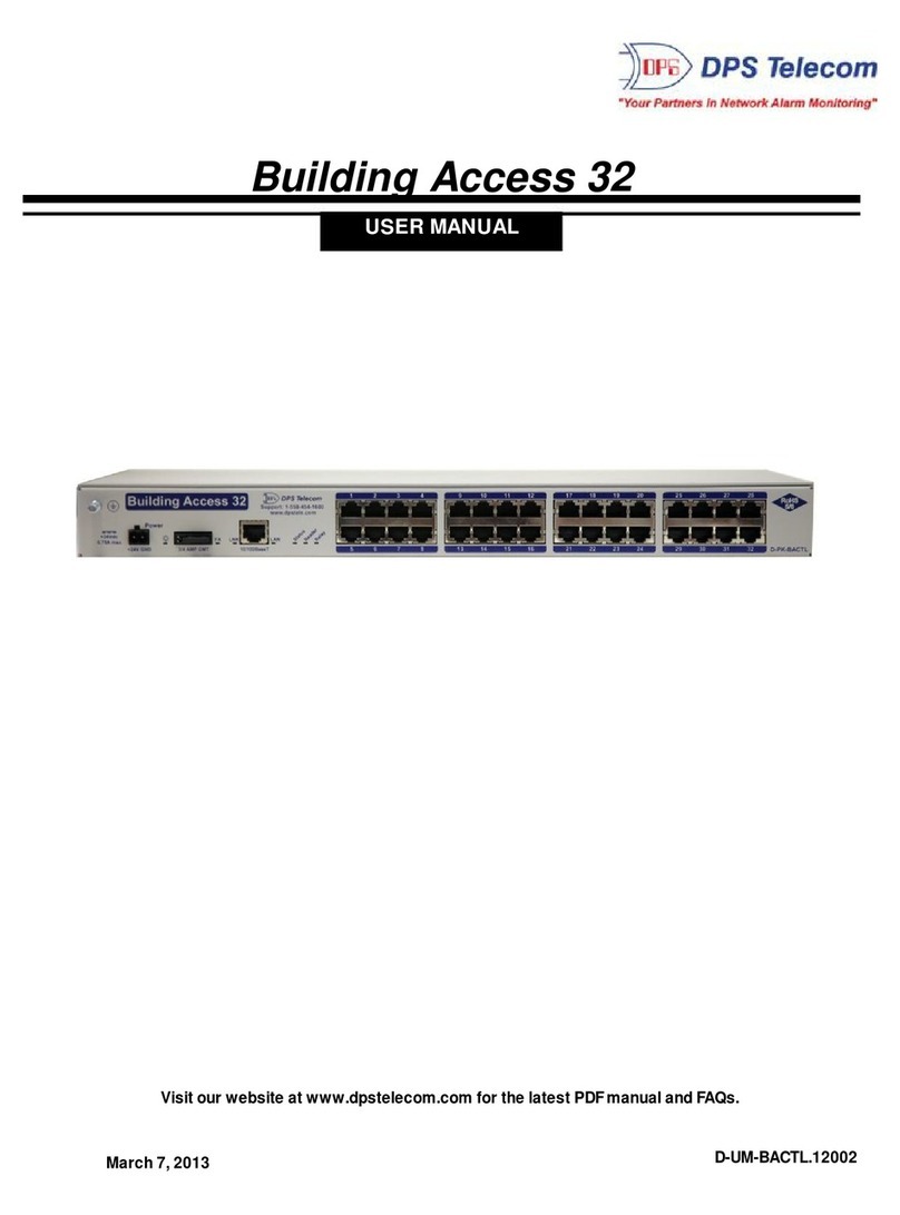
DPS Telecom RPS AB6 User manual

USER MANUAL
Remote Power Switch AB6
February 6, 2017
Visit our website at www.dpstelecom.com for the latest PDFmanual and FAQs.
D-UM-RSPDC-12011 Firmware Version 1.0C

© 2017 DPS Telecom
This document contains proprietary information which is protected by copyright. All rights are reserved. No part of this
document may be photocopied without prior written consent of DPS Telecom.
All software and manuals are copyrighted by DPS Telecom. Said software and manuals may not be reproduced, copied,
transmitted or used to make a derivative work, by either mechanical, electronic or any other means in whole or in part, without
prior written consent fromDPS Telecom, except as required by United States copyright laws.
The material in this manual is for information purposes and is subject to change without notice. DPS Telecomshall not be
liable for errors contained herein or consequential damages in connection with the furnishing, performance, or use of this
manual.
Notice
Revision History
February 23, 2017
February 6, 2017
November 18, 2015
June 18, 2015
April 4, 2013
November 28, 2012
July 23, 2012
May 24, 2012
May 18, 2012
May 11, 2012
December 20, 2011
December 8, 2011
September 9, 2011
May 23, 2011
May 13, 2011
Updates to specifications and shipping list
Shipping list update
Specs update
Added Event Log Section
Added TTY power control feature
Added hardware and software sections for new AMM
Options; clarified D-Wire port functionality
Updated Shipping List
Updated Shipping List and UMPart Number
Updated Front Panel LEDs and Shipping List with D-Wire
Updated shipping list
Added Studded Power Block Cover information
Updated shipping list and fuse information
Added low voltage disconnect and password lockout
features
Initial Release
Preliminary Release

Contents
Visit our website at www.dpstelecom.com for the latest PDF manual and FAQs
Introduction1 1
Specifications1.1 1
Shipping List1.2 3
Hardware Installation2 5
Tools Needed2.1 5
Mounting2.2 5
Power Connections2.3 6
Studded Power Block Cover2.4 6
Power Input Connection2.5 7
Power Output Connection2.6 8
Physical Power Switch Resources3 10
Front Panel LEDs3.1 10
Craft Port3.2 11
LAN Connection3.3 12
Breaker Switches3.4 12
Fuses3.5 13
Alarm Monitoring4 14
Discrete Alarms4.1 14
Analog Alarms4.2 15
Switching Analog Alarms to Current Operation4.2.1 16
D-Wire Sensor Input4.3 17
Control Relay Connectors4.4 17
Display Mapping4.5 18
Initial Configuration5 20
Connecting via the Craft Port5.1 20
Control Power via TTY5.1.1 21
Connecting via LAN5.2 22
Ethernet Configuration5.3 24
Temporarily Disabling the RPS Firewall5.3.1 24
Using the Web Interface6 26
Logging in to the Web Interface6.1 26
Navigating the Web Interface6.2 27
Provisioning the RPS6.3 28
System6.3.1 29
User Profiles6.3.2 30
Ethernet6.3.3 33

Firewall6.3.4 34
6.3.4.1 Disabling Protocols
SNMP6.3.5 36
Notifications6.3.6 38
6.3.6.1 Email Notification Settings
6.3.6.2 SNMP Notification Settings
6.3.6.3 Schedule
6.3.6.4 Testing Notifications
Power Feed Status (Provisioning)6.3.7 41
Base Alarms (Provisioning)6.3.8 43
User Controls (Provisioning)6.3.9 44
6.3.9.1 Configuring Derived Controls
User Analogs (Provisioning)6.3.10 45
Sensors (Provisioning)6.3.11 47
Power Control (Provisioning)6.3.12 48
6.3.12.1 Low Voltage Disconnect
System Alarms (Provisioning)6.3.13 50
Timers6.3.14 52
Date Time6.3.15 53
6.3.15.1 Testing your Automatic Time Adjustment (NTP) Settings
Operating the RPS6.4 55
Power Feed Status (Operation)6.4.1 55
Power Control (Operation)6.4.2 56
Base Alarms (Operation)6.4.3 57
User Controls (Operation)6.4.4 58
User Analogs (Operation)6.4.5 58
Sensors (Operation)6.4.6 59
System Alarms (Operation)6.4.7 59
Event Log6.4.8 61
Device Access6.5 61
Updating Firmware6.6 62
Frequently Asked Questions7 63
Technical Support8 64
End User License Agreement9 65

1
Introduction
1
The RPS AB6 front panel
The Remote Power Switch (RPS AB6), is a rack-mountable power distribution unit (PDU) that allows
you to remotely power on/off and reboot critical devices from any computer on your network.
Via the RPS web browser, you'll be able to toggle power, monitor voltages (and threshold alarms) for
your power feeds, and see fuse-alarms. The web browser supports HTTPS (HTTP secure) for secure
browsing and a number of secure access profiles and password options are available to set access
rights for individual users who might access the RPS web browser.
The unit can also send SNMP traps and email notifications when power is switched on or off, when a
fuse alarm sets, or one of the inputs loses power, so you'll never have to make a trip out to a site to flip a
switch again.
Specifications1.1
Power Inputs: 2 Studded Terminal Block inputs
Voltage: -48 VDC (-36 to -60 VDC) feeds (studded terminal blocks)
Current Draw: 350mA
Power Outputs: 12 (4 connectors, 3 outputs per connector)
Voltage: -48 VDC
Max Current per Feed: 8 Amps
Max Current per Set: 36 Amps per output group
GMT Fuse: 10 Amp max (1 per output)
Output Relays: 8A max @ 60V continuous
Note: Fuses are not included with the with the Remote Power Switch AB6. The user will need to
determine fuse ratings for slots appropriate to their needs (keeping in mind the 36 Amp maximum per
output group).
Interfaces: 1 DB9 RS232 Craft Port
1 RJ45 10/100 BaseT Ethernet Port
1 RJ-11 D-Wire Port
Spare Fuses: 0
Dimensions: 1.75"H x 17"W x 8.5" D
Weight: 5 lbs.
Mounting: 19" or 23" Rack
Visual Interface: 22 front-panel LEDs
2 back-panel LEDs
Operating Temperature: 32°–140° F (0°–60° C)
Operating Humidity: 0%–95% noncondensing
MTBF: 60 years

2
Windows Compatibility: XP, Vista, 7 32/64 bit
*RoHS 5 Approved

3
Shipping List1.2
While unpacking the Remote Power Switch, please make sure that all of the following items are
included. If some parts are missing, or if you ever need to order new parts, please refer to the part
numbers listed and call DPS Telecom at (800) 622-3314.
Shipping List
Remote Power Switch AB6
D-PK-RSPDC
RPS AB6 User Manual
D-UM-RSPDC-12011
RPS AB6 Resource CD
(includes manuals, MIBs, and software)
DB9M-DB9F Download Cable 6 ft.
D-PR-045-10-A-04
23" Rack Ears
D-CS-325-10A-01
6-Pin DC Out Phoenix Connectors
(x4)
2-821-00762-06
19" Rack Ears
D-CS-325-10A-00
Ethernet Cable, 14 ft.
D-PR-923-10B-14
Metric Rack Screws (x4)
2-000-80750-03
Pads (x4)
2-015-00030-00

4
3/8" Ear Screws (x8)
1-000-60375-05
5 Amp Fuse (x12)
2-741-10000-00
Standard Rack Screws (x4)
1-000-12500-06
10 Amp Fuse (x4)
2-741-05000-00
Nut With Star Washer (x9)
2-002-01421-00
Studded Power Block Cover (x2)
2-820-73175-01
Cable Ties (x4)
1-012-00106-00
Optional Accessories
D-Wire Temperature Sensor
D-PK-DSNSR-12001
6 Pin Connectors (For Controls) (x1)
2-821-10635-00
8 Pin Connectors (For Alarms and Analogs)
(x6)
2-821-10835-00

5
Hardware Installation
2
Tools Needed2.1
To install the Remote Power Switch, you'll need the following tools:
Phillips No. 2 Screwdriver
Small Standard No. 2 Screwdriver
7/16" Nut Driver
Mounting2.2
The RPS AB6 with 23" rack ear in flush mount position
The Remote Power Switch mounts in a 19" rack or a 23" rack using the appropriate rack ears for each
size. Attach the rack ears in the flush-mount location shown in the picture above.
Note: Rack ears can be rotated 90° for wall mounting or 180º for other mounting options (not shown).

6
Power Connections2.3
Both the Remote Power Switch AB6's power input and output connections are located on the unit's rear
panel.
The Remote Power Switch AB6 rear panel
Studded Power Block Cover2.4
Before the power input connections can be made the studded power block covers will need to be
removed. To do this use the DPS Standard No. 2 screwdriver. Use the leverage provided by the
screwdriver to lift the latching device as seen in the image below. Once the power connections are
made, ensure that the studded power block covers are reattached to the device.
Howto remove the studded power block cover

7
Power Input Connection2.5
The Remote Power Switch has 2 power feeds, 1 for each set of 6 outputs. Each feed consists of 4
screw-lug power connectors.
WARNING!
The Grounding Lug on the back of the unit provides a permanent connection to
earth ground when connected. The Grounding Lug must be used in order to
comply with standards.
Input Feed B and the Grounding Lug for the RPS AB6
Before you connect a power supply to the Remote Power Switch, test the voltage of your
power supply:
·Connect the black common lead of a voltmeter to the ground terminal of the battery, and connect
the red lead of the voltmeter to the battery's –48 VDC terminal. The voltmeter should read
between –43 and –53 VDC. If the reading is outside this range, test the power supply.
To connect the RPS to a power supply:
Warning: Before connecting power feeds, make sure that the breaker for the power feed you're
connecting is switched off.
1. Use the grounding lug to connect the unit to earth ground. The grounding lug is next to the
symbol. Insert the eyelet of the earth ground cable between the two nuts on the grounding lug
(Ground cable not included). Tighten the grounding lug into place using your 7/16" nut driver.
2. Insert a battery ground into the lower terminal and tighten the nut down on the ground cable
using your 7/16" nut driver. If using the dual feed connector displayed in the example above,
tighten both nuts down on the connector.
3. Insert a –48 VDC line to the unit's upper terminal and tighten the nut down on the -48 VDC line.
If using the dual feed connector displayed in the example above, tighten both nuts down on the
connector.
4. Repeat Steps 2 and 3 for the remaining power inputs.
Note: You must connect Aand B side power inputs to separate power supplies for your Remote
Power Switch to properly function.

8
5. Flip the breaker switch(es) to turn on power.
If the power feeds are connected correctly, you will see LED activity on the front-side of the unit.
Warning: You must connect both terminals on an input feed to output a full 40 Amps.
Power Output Connection2.6
The Remote Power Switch's power feeds are wired to 6-pin plug connectors, 3 per connector. For
each output feed, the -48V cable will be on the left and the ground cable (GND) will be on the right.
Power output connectors on the RPS AB6
To connect your power feeds:
1. If connected, remove the front panel fuse for the power input (or set of power inputs) you'll be working
with. (Example: If connecting input feeds A1-A3, ensure that fuses A1, A2, and A3 are disconnected.)
2. If connected, disconnect the 6-pin power connector from the remote power switch before wiring
power outputs.

9
Inserting the ground cable into appropriate terminal for the output connector
3. Connect the ground cable to the right terminal for each power output; using a small flathead
screwdriver, tighten the GND terminal.
4. Connect the -48V cable to the left terminal for each power output; using a small flathead screwdriver,
tighten the -48V terminal.
A fully wired output connector
5. Once you've wired your equipment to the terminals on the 6-pin plug, connect the plug to the RPS
6. Screw-in the connector to ensure that it does not fall loose from the unit.
7. Re-insert the fuses for the outputs you've just connected.

10
Physical Power Switch Resources
3
The Remote Power Switch's fuses, breaker switches, craft port, LAN, and indicator LEDs are all front-accessible.
Once you've wired power inputs and outputs to the unit, you can perform all other operations from the unit's front
panel.
The front panel of the RPS AB6
Front Panel LEDs3.1
Indicator LEDs for the RPS AB6 are all located on the front panel, and will alert you to the status of your
unit.
LEDs on the front panel of the RPS AB6

11
Front Panel LEDs:
LED
Status
Description
D-Wire
Blinking Green
Transmit over D-Wire
Blinking Red
Receive over D-Wire
Craft
Blink Green
Transmitting over craft port
Blink Red
Receiving over craft port
FA Sum
Solid Red
A fuse is blown/broken on one or more of the power
feeds
Pwr 1-6 (Output A/B)
Solid Red
A fuse is blown/broken on the feed
Solid Green
The output feed is powered
100BT
Solid Green
100 BT connection
Off
10 BT connection
Status
Blink Red
Bootloader application is active; the unit is starting up
Blink Green
The main application is active
Breaker A
Open/ALM
Solid Red = Power A switch is 'On'
Normal
Solid Green = Power A switch is 'Off'
Breaker B
Open/ALM
Solid Red = Power B switch is 'On'
Normal
Solid Green = Power B switch is 'Off'
Craft Port3.2
Remote Power Switch AB6 Front Panel Craft Connection
The unit's front-side craft port is used to access the TTY interface (for initial configuration and local
access to the unit).

12
LAN Connection3.3
RJ45 Ethernet Connection
8
7
5
6 Receive In–(RI–)
4
3 Receive In + (RI+)
2 Transmit Out–(TO–)
1 Transmit Out + (TO+)
Ethernet port pinout
Connect the RPS AB6 to LAN via the unit's front-side 10/100BaseT Ethernet port.
Breaker Switches3.4
The switches on the front panel of the remote power switch control the corresponding power inputs on
the backside of the unit. Use each switch to effectively turn on or off the power feeds on either side of
the unit.
Note: When turning on power using a breaker switch, the corresponding power feeds will honor the
user-set Power-On Sequence. For information about the Power-On Sequence, see the Power
Control (Provisioning) section of this manual.
Breaker Switches are located on the front panel of the RPS AB6
You can store one spare fuse in the small recess above and below each breaker switch.

13
Fuses3.5
The Remote Power Switch AB6's fuses are all located on the front side, each directly corresponding
with the power feeds in the back. Each of the unit's fuse slots accepts up to a 10 amp GMT fuse,
however, 10 Amp fuses are not required. The user should choose fuses rated to fit their application and
should not exceed 40 Amps-worth of fuses per 6-output side (Aor B).
Fuse alarm LEDs are located above the fuses to visually indicate if any of the fuses are blown.
Additionally, from the blue Power Control option under the Operation Menus, you can operate your
power outputs and view the status of each feed as seen in section 5.4.2 Power Control (Operation)

14
Alarm Monitoring
4
Discrete Alarms4.1
The RPS AB6's discrete alarm inputs
The RPS AB6 features 16 discrete alarm inputs - also called digital inputs or contact closures. Discrete
alarms are either activated or inactive, so they're typically used to monitor on/off conditions like power
outages, equipment failures, door alarms and so on.
The RPS AB6's discrete alarm points are single-lead signals referenced to ground. The ground side of
each alarm point is internally wired to ground, so alarm points can either connect as a dry contact or a
contact to ground.
In a dry contact alarm, the alarm lead brings a contact to the ground lead, activating the alarm.
In a contact to ground alarm, a single wire brings a contact to an external ground, activating the alarm.
For a diagram, see the image below.
You can reverse the polarity of each individual discrete alarm point, so that the alarm is activated when
the contact is open.
Discrete alarm points can connect as a dry contact or a contact to ground

15
Analog Alarms4.2
The RPS AB6's analog alarm inputs
The RPS AB6's 8 analog alarm inputs measure continuous ranges of voltage or current. Analog alarms
are typically used to monitor battery voltage, charging current, temperature or other continuously
variable conditions.
The measurement range of the analog channels is –90 to +90 VDC or 4 to 20 mA.
You can connect analog alarm inputs to the RPS AB6 by using the 8-pin analog alarm connectors. For
the 8-pin analog connector's pinout information, see the figure below.
8-Pin Analog Connector Pinout
By default, the analog inputs are configured to measure voltage. You can switch the analog inputs to
measure current by resetting jumpers on the RPS AB6's circuit board. For instructions, see Section
4.2.1, "Switching Analog Alarms to Current Operation."

16
4.2.1 Switching Analog Alarms to Current Operation
Adjustable jumpers on the RPS Ab6 circuit board
By default, the analog inputs are configured to measure voltage. You can switch the analog inputs to
measure current by resetting jumpers on the RPS AB6's circuit board.
WARNING: Always observe anti-static precautions whenever opening the unit.
To test the analog alarm voltage/current jumpers, follow these steps:
1. Make sure the RPS AB6 is depowered and disconnected from all network connections.
2. Remove the screws from the sides of the RPS AB6 case.
3. Slide off the top cover of the case to expose the circuit board.
4. The adjustable jumpers are shown in the figure above. All alarm inputs can be individually
configured for current or voltage operation.
+
Current
Voltage
+
Jumper installed for current
Jumper removed for voltage
Unjumpered/Open Position:
Voltage Operation (default) Jumpered/Closed Position:
Current Operation
4 to 20 mA
Current Source
Transducer
Voltage Source
Transducer
Analog
Channel
Input
-
-
Analog
Channel
Input
250 Ohm
Shunt
Jumper settings for analog alarm inputs
Table of contents
Other DPS Telecom Switch manuals