DPS Telecom D-PK-216RP User manual

USER MANUAL
Remote Power Switch (DC)
November 10, 2017
Visit our website at www.dpstelecom.com for the latest PDFmanual and FAQs.
D-UM-216RP-12001 Firmware Version 1.0J.0183

© 2017 DPS Telecom
This document contains proprietary information which is protected by copyright. All rights are reserved. No part of this
document may be photocopied without prior written consent of DPS Telecom.
All software and manuals are copyrighted by DPS Telecom. Said software and manuals may not be reproduced, copied,
transmitted or used to make a derivative work, by either mechanical, electronic or any other means in whole or in part, without
prior written consent fromDPS Telecom, except as required by United States copyright laws.
The materialin this manualis for information purposes and is subject to change without notice. DPS Telecomshall not be
liable for errors contained herein or consequentialdamages in connection with the furnishing, performance, or use of this
manual.
Notice
Revision History
November 10, 2017
April 14, 2017
November 18, 2015
March 27, 2014
March 21, 2014
February 26, 2014
March 19, 2013
March 12, 2013
July 24, 2012
July 6, 2011
May 10, 2011
September 3, 2010
April 21, 2010
Added support for expansion unit
Removed 16-port option
Spec update
Edited Ping Settings & Control Association
Added Ping Targets, Settings, Relays, and Monitoring
Added Silence Feature to Alarms
Added unit dimensions to specifications page
Added control automation settings
Added 16 port version
Updated images; added power connection instructions &
power relay section
Added information regarding optional alarm, analog, and
control features.
Updated shipping list.
Initial Release

Contents
Visit our website at www.dpstelecom.com for the latest PDF manual and FAQs
Remote Power Switch (DC) Overview1 1
Specifications2 2
Shipping List3 4
Optional Accessories3.1 5
Installation4 5
Tools Needed4.1 5
Mounting4.2 6
Remote Power Controller Back Panel5 7
Main Power Connection5.1 8
Switched Power Input/Output Connections5.2 9
Power Relays5.2.1 10
LAN Connection5.3 10
(Optional) Alarm, Analog, and Control Relay Connector5.4 11
Remote Power Controller Switch Front Panel6 12
Front Panel LEDs6.1 12
Craft Port6.2 12
Ack Button6.3 13
Bypass Password6.3.1 14
Initial Configuration: How to Configure the RPS Ethernet Port7 14
...via Craft Port7.1 14
...via LAN7.2 17
TTY Interface7.3 18
Advanced Configuration: Using the RPS Web Browser8 19
Logging on to the Unit8.1 19
Changing the Default Password8.1.1 20
Edit Menu Field Descriptions8.2 21
System8.2.1 21
User Profiles8.2.2 22
Ethernet8.2.3 23
Serial Port8.2.4 24
Notifications8.2.5 25
Alarms8.2.6 27
8.2.6.1 System Alarms
8.2.6.2 Ping Targets
8.2.6.3 Ping Targets Settings
8.2.6.4 Ping Targets Control Association

Controls8.2.7 32
8.2.7.1 Control Groups
Sensors8.2.8 34
Analogs8.2.9 35
8.2.9.1 Basic Configuration
8.2.9.2 Advanced Configuration
Date and Time8.2.10 39
Timers8.2.11 40
Reboot8.2.12 40
Configuring RPS DC Unit as Expansion9 41
Monitoring Alarms and Issuing Controls10 43
Monitoring Alarms10.1 43
Ping Targets10.1.1 44
Operating Controls10.2 44
Sensors10.3 45
Monitoring Analogs10.4 45
Viewing the Event Log10.5 45
Firmware Upgrade11 46
SNMP Control of Relays12 47
Reference Section13 48
Display Mapping13.1 48
System Alarm Map13.2 54
Frequently Asked Questions14 56
General FAQs14.1 56
SNMP FAQs14.2 58
Technical Support15 59
End User License Agreement16 60

1
Remote Power Switch (DC) Overview
1
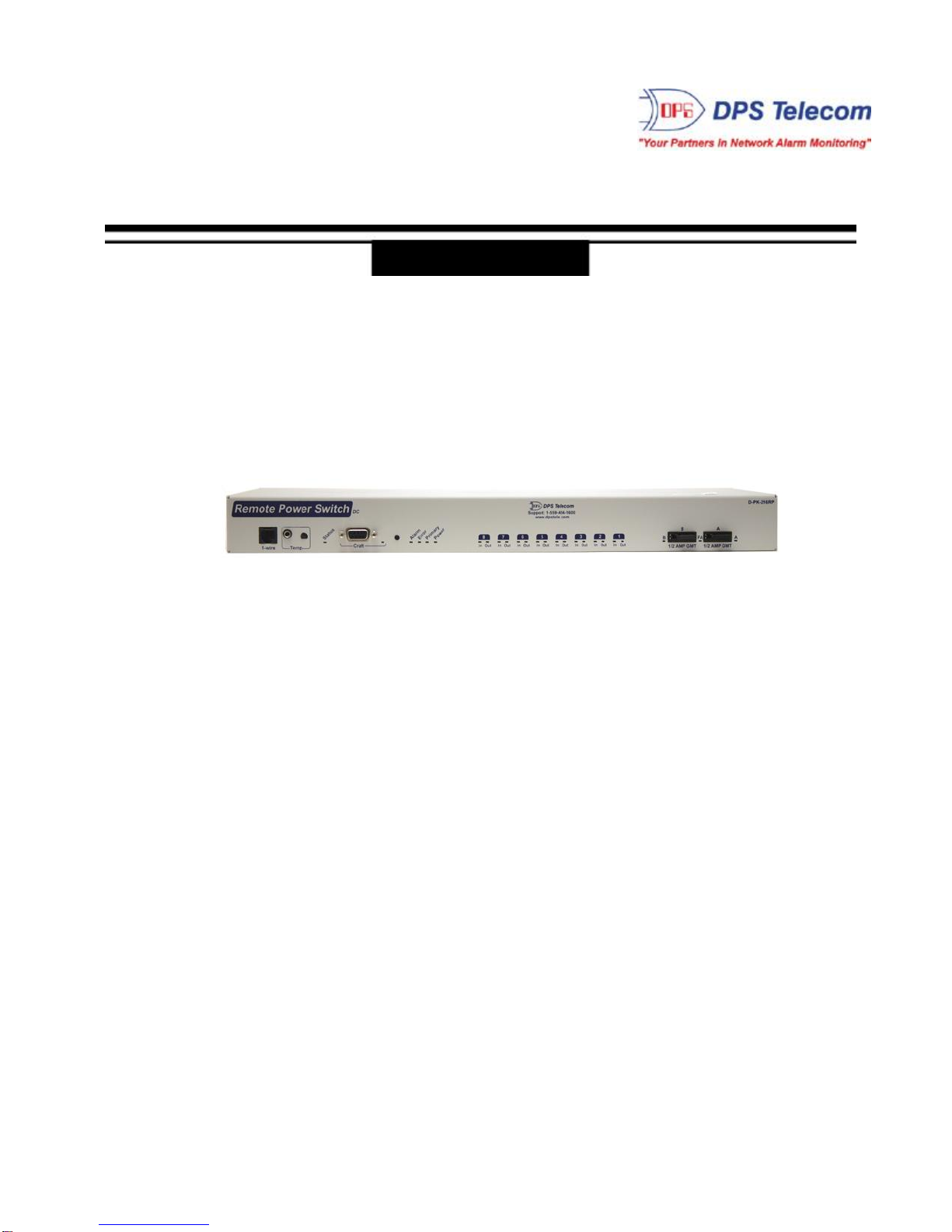
Fig. 1.1 Deploy this power switch at critical locations to switch on, off, and reboot equipment from miles
away.
If you’ve ever had to jump in your truck and drive hours to a site to reboot jammed equipment, you
already know exactly why you need the Remote Power Switch (DC). With this power switch, you’ll
power on/off and reboot all your critical devices - right from your desk. The Remote Power Switch (DC)
allows for eight 8-Amp DC separate power inputs for 8 dedicated outputs.
Using any PC on your network, you can operate controls, check temperature at the site, and keep tabs
on power consumption - all without rolling a single truck. The web browser supports HTTPS (via SSL
encryption), allowing you to browse securely.
From the same intuitive interface, you’ll also be able to monitor and control using the integrated RTU
functions: 16 discretes, 4 analogs, 2 controls.
(Build option)
·Switch on/off and reboot equipment, right fromyour desk chair
·Drastically cuts down on expensive truck rolls - Quickly pays for itself
·Available with 8 power inputs/outputs
·Build Option: RTU version with 16 discretes, 4 analogs & 2 controls OR onlyDC switching power
·SNMP-compatible - Send SNMP traps to your SNMP manager
·Easily daisy-chain multiple power switches
·Enable/disable remote access to the unit for on-site troubleshooting
·Secure web browsing (via SSL encryption) for security-conscious organizations
·Built-in temperature monitoring to track changing environmental conditions
·Automaticallypower-cycle devices based on ping failure
·RoHS 5/6 compliant
Need to control lots of power at a single location? Use the expansion port on the back of the unit to daisy
chain multiple units together. And when working on-site, you can make sure no one back at the CO
disrupts your troubleshooting, you can temporarily disable remote access with the push of a button.

2
Specifications
2
DC Inputs: Available with 8 inputs/outputs OR 16 inputs/outputs
Available with built-in RTUfunctions OR Only DC switching power
Note: RTU build option not available on the 16 input/output version
Current Draw: 200 mA@ 48 VDC
Output Relays: 2.5Amax @ 50Vcontinuous
Interfaces: 1 DB9 craft port
1 - 10BaseT LAN port
4 Phoenix connectors (8 inputs/output)
4-Pin WAGO connector for unit power
Optional: 33.6 Telco modem for backup remote access
Optional: 1 RS232/485 for serial reach through
Optional: External temp jack / probe
SNMP:v1 and v2c
Wire Gauge: Minimum: 24
Maximum: 12
Web interface: HTTP or HTTPS via SSL encryption
Mounting: 19" or 23" Rack mountable; 1 rack unit (RU)
Dimensions: W = 17.026 in.
H= 1.720 in.
D = 7.646 in.
Firmware Upgrade: Upgradeable via LAN or serial
TTY Interface: Yes, through front DB9 craft port (dialup optional), Telnet on TCP port 2002
Op Temperature: 32°–140° F (0°–60° C)
Op Humidity: 0%–95% non-condensing
RoHS: 5 of 6

3
RTU Build Option Includes:
Alarm Termination:Via 50-pin Amphenol connector on back panel
Discrete alarms: 16
Analogs: 4
Controls: 2
Ctrl Commands:On, Off and Reset (off-on)
Internal Temp: 1

4
Shipping List
3
Please make sure all of the following items are included with your Remote Power Switch (DC). If parts
are missing, or if you ever need to order new parts, please refer to the part numbers listed and call DPS
Telecom at 1-800-622-3314.
Remote Power Switch (DC)
D-PK-216RP
Remote Power Switch (DC) User Manual Remote Power Switch (DC) Resource
CD
D-UM-216RP-12001
6 ft. DB9M-DB9F Download Cable 14 ft. Ethernet Cable
D-PR-045-10A-04 D-PR-923-10A-14
x 2 x 2
19" Rack Ear 1/2 Amp GMT Fuse
D-CS-325-10A-00 2-741-00500-00
x 2
Two Standard Rack Screws Four 3/8" Ear Screws
1-000-12500-06 2-000-60375-05

5
x 2
Two Metric Rack Screws 4-Pin WAGO Connector
2-000-80750-03 2-802-04037-00
x 2
Pads 23" Rack Ear
2-015-00030-00
x 4
DC I/O Phoenix Connectors
2-821-00762-08
Optional Accessories3.1
RJ45 to RJ45 connection cable
D-PR-1028-10C-1.5
Installation
4
Tools Needed4.1
To install the Remote Power Switch (DC), you'll need the following tools:
Phillips No. 2 Screwdriver Small Standard No. 2 Screwdriver
PC with web browser and terminal emulator, such as HyperTerminal

6
Mounting4.2
The Remote Power Switch (DC) can be flush or rear-mounted
The Remote Power Switch (DC) mounts in a 19" rack or a 23" rack using the provided rack ears for
each size. Two rack ears locations are provided. Attach the appropriate rack ears in the flush-mount or
rear-mount locations shown above.
The rack ears can be rotated 90° for wall mounting or 180º for other mounting options.

7
Remote Power Controller Back Panel
5
Remote Power Switch (DC) back panel connections
Optional RJ-45 connection

8
Main Power Connection5.1
To connect the NetGuardian to a power supply:
Battery lead left, and Ground right
Grounding Lug left, dual power inputs right
1) Insert a battery ground wire into the connector's right terminal (Shown above) and battery lead into
the left terminal and tighten the screws. Insert the connector into the power plug. Attach a grounding
wire to the grounding lug .
2) Ensure the power status LED is lit up green for correct polarity.
3) Insert the local fuse into the fuse holder.
4) The front panel status LED should flash RED and GREENto indicate that the unit is operating.
Note: Always use safe power practices when making power connections. Make sure the power wires are
not active before making any power connections

9
Switched Power Input/Output Connections5.2
Your switched power feeds will be wired to 8-pin connectors, with 2 inputs and 2 outputs per connector,
and plugged into any of the power in/out receptacles on the rear of your Remote Power Switch.
Your power feeds will be connected to the remote power switch via the 8-pin power connector.
To connect your power feeds:
1. If connected, remove the front panel fuses.
2. If connected, disconnect the 8-pin power connector from the remote power switch before wiring
power inputs or outputs.
3. For each input/output, the Battery cable will be on the left and the RTN/GND line will be on the right.
Connect the RTN/GND cable to the terminal for the input or output. Using a small flathead
screwdriver, tighten the terminal.
Inserting the a wire into the connector
Tightening the terminal to hold the wire in place
4. Connect the Battery line to the terminal for the input or output. Using a small flathead screwdriver,
tighten the terminal.

10
A connector wired with one input and one output
5. Once you've wired your Battery and RTNlines to the 8-pin plug, connect the plug to the Remote
Power Switch.
6. Using your flathead screwdriver, tighten the screws on the left and right side of the plug to fasten it
securely to the unit.
7. Reinsert the Remote Power Switch's fuses to power the unit.
5.2.1 Power Relays
The Remote Power Switch's power outputs are internally relayed from the unit's battery inputs. The
relay allows you to control power to your outputs. The unit's battery feeds are polarity insensitive,
allowing you to connect and control both positive and negatively powered equipment with the your
Remote Power Switch.
The unit's power outputs are relayed internally, allowing you to control your outputs
+VDC
-VDC
Batt
+
-
RTN
-
+
Table: Connecting the correct leads to
your BATT and RTN inputs and
outputs
LAN Connection5.3
To connect the Remote Power Switch (DC) to the LAN, insert a standard RJ45 Ethernet cable into the
10BaseT Ethernet port on the back of the unit. If the LANconnection is OK, the LNK LED will light
SOLID GREEN.

11
(Optional) Alarm, Analog, and Control Relay Connector5.4
The Remote Power Switch's 16 discrete alarm inputs, 2 control relay outputs, and 4 analog inputs are all connected
through the 50-pin amphenolconnector.

12
Remote Power Controller Switch Front Panel
6
Front Panel LEDs6.1
The Remote Power Switch's front panel LEDs indicate communication and alarm reporting status.
LED
Status
Description
Craft
Blink Green
Transmit over craft port
Blink Red
Receive over craft port
Alarm
Blink Green
Transmit over Modem port
Blink Red
Receive over Modem port
Error
N/A
Reserved for future use
Primary
Blink Green
Transmit over Telco Port
Blink Red
Receive over Telco Port
Power
Solid Green
The unit is powered
Power In
Solid Green
Indicates that a power input feed is active
Power Out
Solid Green
Indicates that a power output feed is active
Descriptions of the front panel LEDs for the Remote Power Switch
Craft Port6.2
Use the front panel craft port to connect the Remote Power Switch (DC) to a PC for onsite unit configuration. To use
the craft port, connect the included DB9 download cable from your PC's COM port to the craft port. Pinout is shown
above for reference, but this is a standard DB9 to DB9.
Remote Power Switch (DC) Front panel connections.

13
Ack Button6.3
Hold the Ack button for 3 seconds to disable remote access to the unit, the status LED will turn Red. This is
usefulwhile on-site, so that unit settings cannot be changed while you are working. Disabling remote access also
means you cannot change the state of controlrelays or reboot the system. To Restore access, hold Ack button
again for 3 seconds, the status LED willturn green.

14
6.3.1 Bypass Password
Hold button while unit is booting up to bypass password in the event of a forgotten password.
Initial Configuration: How to Configure the RPS
Ethernet Port
7
Before you can connect to your NetGuardian remotely, you must first configure the ethernet ports. Initial
ethernet configuration is performed via the unit's TTYinterface and a craft connection or a LAN
connection that mimics the NetGuardian's factory set IP and subnet mask.
NOTE: For craft port connection, use the provided DB9 cable. DPS Part # D-PR-045-10A-04
Alternative option: You can skip the TTYinterface by using a LAN crossover cable directly from your
PC to the Remote Power Switch (DC) and access its Web Browser.
...via Craft Port7.1
1. Make sure you are using the straight through (1 to 1) Male to Female DB9-DB9 download cable provided with
your Remote Power Switch (DC) to make a craft port connection. We'll be using HyperTerminal to connect to
the unit in the following example - however, most terminal-emulating programs should work.
2. To access HyperTerminal using Windows, click on the Start menu > select Programs > Accessories >
Communications > HyperTerminal.

15
3. At the Connection Description screen, enter a name
for this connection. You may also select an icon. The
name and icon do not affect your ability to connect to the
unit.
4. At the Connect To screen, select Com port you'll
be using from the drop down and click OK. (COM1 is
the most commonly used.)
5. Select the following COM port options:
• Bits per second: 9600
• Data bits: 8
• Parity: None
• Stop bits: 1
• Flow control: None
Once connected, you will see a blank, white
HyperTerminal screen. Press Enter to activate the
configuration menu.
6. When prompted, enter the default user name
admin and password dpstelecom. NOTE: If you
don't receive a prompt for your user name and
password, check the Com port you are using on your
PC and make sure you are using the cable provided.
Additional cables can be ordered from DPS Telecom:
Part number D-PR-045-10A-04
7. The Remote Power Switch (DC)'s main menu will
appear. Type C(config), then E(ethernet) to reach the
ethernet menu. Use the arrow keys to move your cursor
to the right fields and configure the unit's IP address,
subnet mask, and default gateway.
8. ESC to the main menu. When asked if you'd like to
save your changes, type Y for Y)es. Reboot the
Remote Power Switch (DC) to save its new
configuration.

16
Now you're ready to do the rest of your configuration via LAN. Plug your LAN cable into the Remote Power Switch
(DC) and see section "Logging On to the Remote Power Switch (DC)" to continue using the Web Browser.
Table of contents
Other DPS Telecom Switch manuals
Popular Switch manuals by other brands

D-Link
D-Link DXS-3600-16S Quick installation guide

Cooper Bussmann
Cooper Bussmann UL98 Series manual

WIKA
WIKA RLS-1000 operating instructions

Raritan
Raritan Dominion SX DSXA-16-DL Quick setup guide

Motorola
Motorola WS2000 - Wireless Switch - Network Management... installation guide

WTI
WTI Net Reach RPC-4840N Specification sheet