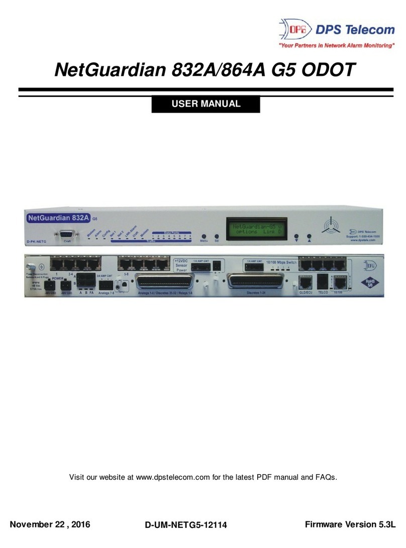
DPS NetGuardian 832A User manual

Building Access System
USER MANUAL
“Your Partners in Network Alarm Management”
Visit our website at www.dpstele.com for the latest PDF manual and FAQs.
D-OC-UM04C.02100
For the NetGuardian 832A

Revision History
11/28/01 - UM01A.04100 User Manual released.
1/14/02 - UM01A.04101 Added Point Displays - Appendix A
11/22/04 - Building Access User Manual (D-OC-UM04B.22100) released.
12/02/04 - Building Access User Manual (D-OC-UM04C.02100) released.
This document contains proprietary information which is protected by copyright. All rights are reserved. No part of this document may be photocopied with-
out prior written consent of DPS Telecom.
All software and manuals are copyrighted by DPS Telecom. Said software and manuals may not be reproduced, copied, transmitted or used to make a deriva-
tive work, by either mechanical, electronic or any other means, in whole or in part, without prior written consent from DPS Telecom, except as required by
United States copyright laws.
© Copyright 2002, DPS Telecom
Notice
The material in this manual is for information purposes and is subject to change without notice. DPS Telecom shall not be liable for errors contained herein or
for incidental or consequential damages in connection with the furnishing, performance, or use of this manual.

iii
Table of Contents
Table of Contents
Visit our website at www.dpstele.com for the latest PDF manual and FAQs.
Overview Chapter 1 . . . . . . . . . . . . . . . . . . . . . . . . . . . . . . . . . . . . . . . . . . . . . . . . . . .1
1.1 Summary of Features . . . . . . . . . . . . . . . . . . . . . . . . . . . . . . . . . . . . . . . . . . . . . . . . . . .1
1.2 Introduction . . . . . . . . . . . . . . . . . . . . . . . . . . . . . . . . . . . . . . . . . . . . . . . . . . . . . . . . . .2
Hardware Chapter 2 . . . . . . . . . . . . . . . . . . . . . . . . . . . . . . . . . . . . . . . . . . . . . . . . . . . . . . . . .3
2.1 Shipping List . . . . . . . . . . . . . . . . . . . . . . . . . . . . . . . . . . . . . . . . . . . . . . . . . . . . . . . . .3
2.2 Specifications . . . . . . . . . . . . . . . . . . . . . . . . . . . . . . . . . . . . . . . . . . . . . . . . . . . . . . . . .4
2.3 Hardware Installation . . . . . . . . . . . . . . . . . . . . . . . . . . . . . . . . . . . . . . . . . . . . . . . . . . .5
2.3.1 Site Preparation . . . . . . . . . . . . . . . . . . . . . . . . . . . . . . . . . . . . . . . . . . . . . . . . . . .5
2.3.2 Installation Steps Overview . . . . . . . . . . . . . . . . . . . . . . . . . . . . . . . . . . . . . . . . . .5
2.3.3 Mounting Instructions . . . . . . . . . . . . . . . . . . . . . . . . . . . . . . . . . . . . . . . . . . . . . .6
2.3.3.1 Entry Control Unit . . . . . . . . . . . . . . . . . . . . . . . . . . . . . . . . . . . . . . . . . . .6
2.3.3.2 ECU with conduit . . . . . . . . . . . . . . . . . . . . . . . . . . . . . . . . . . . . . . . . . . . .6
2.3.3.3 Keypad . . . . . . . . . . . . . . . . . . . . . . . . . . . . . . . . . . . . . . . . . . . . . . . . . . . .6
2.3.4 Power Connection . . . . . . . . . . . . . . . . . . . . . . . . . . . . . . . . . . . . . . . . . . . . . . . . . .7
2.3.4.1 Entry Control Unit . . . . . . . . . . . . . . . . . . . . . . . . . . . . . . . . . . . . . . . . . . .7
2.3.4.2 Door Strike . . . . . . . . . . . . . . . . . . . . . . . . . . . . . . . . . . . . . . . . . . . . . . . . .8
2.3.5 Communication Lines . . . . . . . . . . . . . . . . . . . . . . . . . . . . . . . . . . . . . . . . . . . . . . .9
2.3.5.1 NetGuardian . . . . . . . . . . . . . . . . . . . . . . . . . . . . . . . . . . . . . . . . . . . . . . . .9
2.3.5.2 Entry Control Unit . . . . . . . . . . . . . . . . . . . . . . . . . . . . . . . . . . . . . . . . . .10
2.3.5.3 Daisy Chain Options . . . . . . . . . . . . . . . . . . . . . . . . . . . . . . . . . . . . . . . . .10
2.3.5.4 Keypad . . . . . . . . . . . . . . . . . . . . . . . . . . . . . . . . . . . . . . . . . . . . . . . . . . .11
Unit Configuration Chapter 3 . . . . . . . . . . . . . . . . . . . . . . . . . . . . . . . . . . . . . . . . . . . . . . . . .12
3.1 Addressing the Entry Control Unit . . . . . . . . . . . . . . . . . . . . . . . . . . . . . . . . . . . . . . .12
3.1.1 Additional Switch Settings . . . . . . . . . . . . . . . . . . . . . . . . . . . . . . . . . . . . . . . .13
Operation Chapter 4 . . . . . . . . . . . . . . . . . . . . . . . . . . . . . . . . . . . . . . . . . . . . . . . . . . . . . . . .14
4.1 Entry Control Unit Operation . . . . . . . . . . . . . . . . . . . . . . . . . . . . . . . . . . . . . . . . . .14
4.1.1 LED Verification and Local Testing . . . . . . . . . . . . . . . . . . . . . . . . . . . . . . . . .15
4.1.2 ECU Speaker Operation . . . . . . . . . . . . . . . . . . . . . . . . . . . . . . . . . . . . . . . . . .15
4.2 Keypad LED Operation . . . . . . . . . . . . . . . . . . . . . . . . . . . . . . . . . . . . . . . . . . . . . . .16
4.2.1 Basic Operation . . . . . . . . . . . . . . . . . . . . . . . . . . . . . . . . . . . . . . . . . . . . . . . . .16
Display Mapping Appendix A . . . . . . . . . . . . . . . . . . . . . . . . . . . . . . . . . . . . . . . . . . . . . . . . .17

1
Overview • Summary of Features
1.1 Summary of Features
• Centralized entry management and control
• Controls and regulates up to 16 door entry points
• Users can be granted access by day of the week, time of day, and location
• Supports small to medium sized sites
• Each site functions independent of the master
Fig. 1.1 - The Building Access System gives network alarm managers the ability to control and regulate door access.
Overview
Chapter 1
NetGuardian 832A
Keypad
Entry Control Unit

2
Overview • Introduction
Fig. 1.2 – The BAS can control and regulate up to 16 door entry points.
1.2 Introduction
BAS Functional Diagram
The Building Access System (BAS) is a comprehensive building entry management system that provides centralized door
access control. With the system in place, managers can maintain a database of all personnel access as well as the time of
day and location that access was granted. The three part system consists of the NetGuardian 832A, the Entry Control Unit
(ECU), and the Keypad.
NetGuardian 832A
The NetGuardian maintains a list of personnel who are authorized to access the facility. It records all valid entries,
attempts, and the time of each action in non-volatile RAM. It can also receive a control from T/MonXM to remotely open a
door. However, should the NetGuardian lose connection with the IAM, the unit is still able to make local entry decisions.
Front panel LEDs indicate communication activity between the NetGuardian and the ECU. The unit supports up to 1,300
user profiles for distribution between door entry points.
Entry Control unit (ECU)
The Entry Control Unit (ECU) reduces and distributes the control and interface logic of the NetGuardian. Any access
code that is entered on the keypad is accepted by the ECU and passed on to the NetGuardian for validation. If the access
code is valid, the ECU accepts a command from the NetGuardian to energize the local relay to open the door. In the event
of communication failure with the NetGuardian, the ECU will verify entered access codes against a backup set of valid
access profiles previously downloaded from the NetGuardian.
The ECU is powered by -48VDC and is wall mountable on the interior of the building. The unit has front panel LEDs
indicating fuse alarm, keypad status, shelf status, and NetGuardian communication.
Keypad
The weather-shielded keypad is mounted on the exterior of the building and is designed to withstand a wide temperature
range. To prevent unauthorized access, there is no amount of tampering that can be done to the keypad to cause the door to
open.
T/MonXM software
The BAS system functions as a software module in T/MonXM software. It is a profile based access system that assigns
each user with a unique user profile that contains information on which NetGuardians are allowed to be accessed, the door
numbers, days of the week access is allowed, a start/stop time, and a beginning and ending date (primarily for contractors,
new employees, or short term employees). The user profile field includes the user’s name, title, numeric user ID (7 digit
minimum - 14 digit maximum), and a 30 character miscellaneous description.
Relay
To Door Strik
e
Relay
To Door Strike
To
D
oor Sensor
Keypad
To
Door Sensor
Keypad
116
............
............
Door Controller #1 Door Controller #16

3
Hardware • Shipping List
Entry Control Unit
(D-PK-ECU01)
Environmentally sealed Keypad with 14 foot cable
(shown) (D-PK-ECU01-12001)
or
Keypad with 14 foot cable with an additional RJ45 jack
(not shown) for customized cable lengths
(D-PK-ECU01-12002)
Hardware
Chapter 2
2.1 Shipping List
Mounting screws
(Two - 3/4” wood screws, two - 3/4” PH screws, two -
lock washers, and two - hex nuts)
14 ft. RJ45 cable
(D-PR-923-10A-14)
Two
1/2 amp fuses
One 4-pin comm line screw-
lug jack and one 2-pin power
screw-lug jack
BAS user manual (UM01A.04100),
ECU Mounting Template, and Warranty Card
Building Access System
USER MANUAL
“YourPartners in Network Alar m Management”
Visit our website at www.dpstele.com for the latest PDF manual and FAQs.
UM01A.04100
For the NetGuardian 832A
3.5"
7/8"
4"
DPSTelecom
“YourPartners inTelecom Management Networks”
Mounting template
for KeypadDevice (Date: 11-28-01)
1.75"
mounting screws
DPSTelecom
“YourPartners in TelecomManagement Networks”
Keyhole mounting template
for GLD (Date: 8-8-00) and
ECU (Date: 10-12-01)
Keypad shipped in
separate box
ECU Box
Keypad Box
Keypad Mounting Template
and 4 mounting screws
x2 x2 x2 x2
x4
x2 x1 x1

4
Hardware • Specifications
2.2 Specifications
Specifications ECU Keypad (Sm) Keypad (Lg)
Dimensions
Mounting
Power Input
Current draw
Interfaces
Protocols
Temp range
Humidity range
Fuse
Audible
Visual
7 1/2” X 6 7/8” X 1 5/8”
0° to 60°C
(32° to 140°F)
4 1/2” X 5” X 2 1/2”3” X 5” X 2 1/2”
wall mount wall mount wall mount
-48 VDC N/A N/A
1 four-pin screw lug jack RJ45 RJ45
N/A N/A N/A
-40° to +80°C
(-40° to +176°F)
-40° to +80°C
(-40° to +176°F)
0% to 95% non-condensing
GMT 1/2 amp N/A N/A
Speaker N/A N/A
LEDs LEDs LEDs
35 mA N/A N/A
Environmentally sealed Environmentally sealed

5
Hardware • Hardware Installation
2.3 Hardware Installation
2.3.1 Site Preparation
Tools needed:
• Phillips screwdriver
• Small standard No.2 screwdriver (1/16” for screw-lug connectors)
• Wire strippers/cutter
Materials needed:
• 1/2” conduit
Precautions
• Pull fuses before connecting -BAS power feed.
• Always observe electrostatic discharge (ESD) precautions.
2.3.2 Installation Steps Overview
• Mount the ECU and the Keypad (See section 2.3.3)
• Connect power to the ECU (See section 2.3.4)
• Connect communication lines between the NetGuardian, ECU, and Keypad (See section 2.3.5)
• Set the ECU’s address(es) (See section 3.1)
• Provision the NetGuardian and the IAM (or T/MonXM) with the appropriate information (See the BAS software
module in the T/MonXM user manual)

6
Hardware • Mounting Instructions
Mount the keypad bracket to the
wall using the four screw holes
Run the RJ45 cable
from keypad
through the bracket
opening
Weave the RJ45
cable through the
securing barriers
Secure the keypad
onto the bracket
using the four
side-panel screw
holes and security
screws
(two on each side)
2.3.3.3 Keypad
1. Mount the keypad bracket on the desired surface using the four screw holes by using the mounting bracket (See figure
2.3.3.3).
2. Before securing the keypad onto the bracket, weave the RJ45 cable through the securing barriers and out the circular
bracket opening (See figure 2.3.3.3).
3. Secure the keypad onto the bracket by inserting the four side panel screws into the unit (See figure 2.3.3.3).
Fig. 2.3.3.3 – The keypad can be mounted as shown above.
2.3.3 Mounting Instructions
2.3.3.1 Entry Control Unit (ECU)
The Entry Control Unit (ECU) can be mounted on any surface using the mounting screws. To mount the ECU, place the
mounting screws in the desired location using the mounting template and place the ECU on the screws by sliding the unit
down as shown in figure 2.3.3.1. To avoid damaging the circuit board, make certain that the mounting screws do not pro-
trude more than 1/8” out of the mounting surface (or less to mount the unit flush to the surface).
Fig. 2.3.3.1 – The ECU can be mounted as shown above.
Slide the ECU on to the
mounting screws
2”
Fig. 2.3.3.2 - ECU with 1/2” conduit fittings.
2.3.3.2 ECU with conduit
The 3/4” circular openings support standard 1/2” conduit fittings (not included). Secure power and communication wires
by installing 1/2” inch conduit in any of the 3/4” circular openings on the ECU (See figure 2.3.5.4a). To attach the conduit,
remove the 3/4” pre-cut metal circles from the case and insert the 1/2” conduit or the nylon plug.
1/2” conduit 1/2” conduit

7
Hardware • Power Connection
2.3.4 Power Connection
2.3.4.1 Entry Control Unit (ECU)
1) Remove the fuse from the ECU.
2) Remove the screw-lug barrier plug from the bottom of the ECU (See figure 2.3.4.1).
3) Connect a -48VDC power lead and a GND lead to the corresponding terminals of the 2-position barrier plug.
4) All barrier screws should be seated firmly but not over-tightened so as to nick the bare wire.
5) Push the plug firmly back into its appropriate location on the bottom of the case.
6) Once the hardware connections are complete, power the unit(s) by applying -48VDC to the power lead.
7) Re-insert the fuse.
Note: Observe polarity when connecting battery leads. If using the -48VDC red/black cables supplied with the unit, connect black to
GND and red to -BATT. Standard gauge is 20AWG, but may vary between 18-24AWG.
Fig. 2.3.4.1 - Connect power wires to the removable screw-lug jacks.
Ground -48VDC
power lead

8
Hardware• Door Strike
positive (+)
power feed
negative (-)
power feed
Door strike
with integrated
door sensor
2.3.4.2 Door Strike
When a valid password is entered on the keypad, the NetGuardian will send a command to the ECU to operate the relay
to energize the door strike. Follow the directions below to connect the door strike and door sensor to the ECU.
1) Using the screw-lug connectors, connect the door strike power wires to SA1 (+) and SB1 (-).
2) Connect the door sensor to RTN (return) and OP1 (opto isolated alarm for the door sensor).
To integrated
door sensor
To external door
sensor
(if not integrated into the
door strike)
Screw-Lugs Description
AP-
AP+
PA1
PB1
SA1
SB1
PA2
Screw-Lugs Description
PB2
SA2
SB2
Auxiliary Power (+). Constant (non-switched)*. RTN
OP1
RTN
OP2
RTN
OP3
FUSE
Auxiliary Power (-). Constant (non-switched)*.
External power input for solenoid A1 (optional).
Solenoid A1. Positive power feed to door strike.
Solenoid B1. Negative power feed to door strike.
External power input for solenoid B1 (optional).
Reserved for future use.
Door sensor return.
Opto isolated alarm for door sensor.
Reserved for future use.
Fuse alarm.
Fig. 2.4.3.2 - Connect the door strike and the door sensor to the ECU.
Tbl. 2.4.3.2 - ECU screw-lug jack descriptions.
* -24VDC
RLY1
RLY2

9
Hardware • Communication Lines
2.3.5 Communication Lines
2.3.5.1 NetGuardian
The NetGuardian’s RS485 ports can support up to 8 ECU’s each. See section 2.3.5.2 for ECU connection and pinout
information. If connecting more than one ECU, use a daisy-chain configuration as needed (See section 2.3.5.3 for daisy-
chain options). Use cable number D-PR-652-10A-00.
Note: If using a daisy-chain configuration, there is a maximum connection length of 1,500 feet between the NetGuardian and the last
ECU.
Fig. 2.3.5.1a - NetGuardian back panel with RS485 port.
5 4 3 2 1
9 8 7 6
TX+
RX-
PIN# Signal
1
2
3
4
5
6
7
8
9
TX+
NC
NC
RX+
NC
TX-
NC
NC
RX-
Fig. 2.3.5.1b - NetGuardian RS485 pinout information.
RX+
TX-
NG pin # Wire Color
1 (TX+)
4 (RX+)
6 (TX-)
9 (RX-)
NetGuardian
RS485 DB9
Wht/Blu
Wht/Org
Blu/Wht
Org/Wht
Typical RS485 ports
Connect up to 8 ECUs
per RS485 port
Cable # D-PR-652-10A-00

10
Hardware • Entry Control Unit
2.3.5.2 Entry Control Unit (ECU)
The ECU reduces and distributes the control and interface logic of the BAC. To connect the ECU to the BAC, follow the
directions below.
1. Connect the ECU to one of the 4-wire RS485 ports located on the back panel of the NetGuardian. (See figure 2.3.5.2
for pinout information and section 2.3.5.1 for connection options). Use cable number D-PR-652-10A-00.
2. Connect communication wires from the host to the ‘IN’ terminals of the 4 position barrier plug. (See figure 2.3.5.2).
3. If daisy chaining, connect the communication wires of the second ECU you are using into the screw lug jacks of the
first ECU (follow the connection and pinout information in section 2.3.5.3).
Fig. 2.3.5.2 - Connect the NetGuardian to the ECU using cable number D-PR-652-10A-00.
Tx+
Rx-
Rx+
Tx-
1
4
6
9
NetGuardian
RS485 DB9
NG pin # To ECU Wire Color
1 (TX+)
4 (RX+)
6 (TX-)
9 (RX-)
RX+
TX+
RX-
TX-
Wht/Blu
Wht/Org
Blu/Wht
Org/Wht
NetGuardian to ECU Interface Cable Pinout
Information (D-PR-652-10A-00)
Tx-
Tx+
Rx+
Rx-
2.3.5.3 Daisy chain options
Up to eight ECUs can be connected to one RS485 port on the NetGuardian (there is a maximum distance of 1,500 feet
between the NetGuardian and the last ECU in the daisy chain). To connect the ECUs in a daisy chain configuration, connect
communication lines between the ECUs in a parallel fashion (i.e. TX+ to TX+, TX- to TX-, RX+ to RX+, and RX- to RX-).
See figure 2.3.5.3.
Fig. 2.3.5.3 - ECU daisy chain configuration.
Tx-
Tx+
Rx-
Rx+ Rx+
Rx-
Tx+
Tx-
NetGuardian
RS485 DB9
Tx+
Tx-
Rx+
Rx-

11
Hardware • Keypad
2.3.5.4 Keypad
The keypad interfaces with the ECU via an RJ45 cable (attached to the keypad). The ECU has three circular openings
(two on top, one on bottom) where the RJ45 cable can be inserted. The RJ45 jack is located in the inside of the ECU cas-
ing. Insert the RJ45 cable through one of the openings and connect it to the RJ45 jack. See table 2.3.5.4 for pinout informa-
tion.
Note: There is a maximum distance of 14 feet between the keypad and the ECU.
14 ft. RJ45 cable to
ECU (included)
(D-PR-923-10A-14)
Fig. 2.3.5.4 - Connect the RJ45 cable from the keypad to the ECU.
ECU
1
2
3
4
5
6
7
8
RJ45 Pin# Wire Color Function
1
2
3
4
5
6
7
8
Wht/Org
Org/Wht
Wht/Grn
Blu/Wht
Wht/Blu
Grn/Wht
Wht/Brn
Brn/Wht
Transmit positive (Tx+)
Transmit negative (Tx-)
Receive positive (Rx+)
No connection
No connection
Receive negative (Rx-)
No connection
No connection
Tbl. 2.3.5.4 - RJ45 pinout information.
RJ45 Jack

12
Unit Configuration
Unit Configuration
Chapter 3
3.1 Addressing the Entry Control Unit
Each ECU must be given a unique address. There is an eight-position switch located on the ECU circuit board that allows you
to set a unique address for each unit. However, only the first 4 switches are used for addressing the units (See figure 3.1a for
ECU address switch positions). See section 3.1.1 for additional switch settings.
Fig. 3.1a - ECU circuit board.
Speaker
jumper (J15)
(See section
4.2.1)
Addressing
Switch
Off
1 2 3 4
ECU
Address
ECU
Address
Switch
Position
Switch
Position
1
2
3
9
8
7
6
5
4
13
16
15
14
12
11
10
Off
1 2 3 4
Off
1 2 3 4
Off
1 2 3 4
Off
1 2 3 4
Off
1 2 3 4
Off
1 2 3 4
Off
1 2 3 4
Off
1 2 3 4
Off
1 2 3 4
Off
1 2 3 4
Off
1 2 3 4
Off
1 2 3 4
Off
1 2 3 4
Off
1 2 3 4
Off
1 2 3 4
Fig. 3.1b - Addressing switch positions.

13
Unit Configuration • Additional Switch Settings
3.1.1 Additional Switch Settings
Additional ECU settings can be set using the DIP switch. Switch 7 should be set to “On” (this sets the default baud rate at
9600 for communication with the NetGuardian).
DIP switch 6 will control relay 1 and relay 2. A relay is used to control the door strike. Default setting is "Off," which has the
relay idle in a open (de-energized) condition. In this configuration, when a valid code is entered the relay energizes and acti-
vates the door strike. When DIP switch 6 is "On," the relay will idle in an energized state. When a valid code is entered, the
relay will de-energize — releasing the door strike.
To reverse the ECU opto points 1-3 set DIP switch 8 to “On” — set to “Off” for Normal settings.
Switch 5 is reserved for future use. See Figure 3.1.1 for switch positions.
Off
1 2 3 4 5 6 7 8
ECU addressing
switches
“On” sets default baud rate (9600)
and “Off” sets baud rate to 2400
Reserved of
future use
“Off” sets ECU opto points 1-3 to Normal
“On” reverses ECU opto points 1-3
Fig. 3.1.1 – Additional switch settings.
“On” sets relays to Normally Closed
“Off” sets relays to Normally Open

14
Operation
LED Status Description
Fuse Alarm
Keypad Stat
Shelf Stat
BAC Comm
Solid red Blown fuse
Solid red
Solid green Door relay active (i.e. door unlocked) or “Propped
Door Command” is active
Lockout (prevents user access for 5 minutes)
Flashing green
Flashing red
Receiving polls normally
Communication problem or failure*
Flashing green
Flashing red
NetGuardian serial communication (Tx)
NetGuardian serial communication (Rx)
Tbl. 4.1 - ECU LED indications.
*The ECU will use local password verification to permit access as long as the communication problem persists.
Fig. 4.1 – ECU LEDs give at-a-glance status indication.
Operation
Chapter 4
4.1 Entry Control Unit (ECU) Operation
The ECU has four LEDs for fuse alarm, communication activity, and shelf activity. See table 4.2 for specific LED
descriptions.
Flashing green Button being pressed on keypad
Flashing red Open door lockout
4.1.1 LED Verification and Local Testing
Upon powering up the ECU all four front panel LEDs will flash green to red one time. If the unit is functioning properly, the
Shelf Stat LED will flash green every 2 seconds (this functions as a unit status indicator - if the Shelf Stat LED is flashing red it
means the unit is not polling properly). During communication with the NetGuardian, the BAC Comm LED will rapidly alter-
nate between green and red. See table 4.1 for specific LED indicators.

15
Operation • ECU Speaker Operation
4.1.2 ECU Speaker Operation
The ECU offers audible notification of specific events.
Normal Entry Operation
After entering a valid “Entry” password and the door strike has been energized, users have approximately 45 seconds to
enter through the door and close the door behind them before an alarm condition occurs. Once a valid “Entry” password is
accepted by the ECU, a 15-second silent time-lapse will occur followed by a 30-second slow (warning) beep, during which
time the user must enter through the door and close it behind them. An alarm condition will occur after 45 seconds and will
be indicated by a faster beep.
Normal Exit Operation
Upon exiting through the door, users must enter a valid “Exit” password within 30 seconds of opening the door. A 30-sec-
ond slow (warning) beep will sound during which time the user must enter a valid “Exit” password and close the door
before an alarm condition occurs.
Door Alarm
A fast beep indicates a door alarm has occurred. The user must re-enter or re-exit (with a valid password) in order for the
alarm to clear. While the door alarm remains standing (uncleared), the speaker will cycle between 12 minutes on (fast beep)
and 3 minutes off. Because a fast beep indicates a door alarm, open door lockout will be cancelled, and the keypad will be
enabled, even if the door is open.
Propped Door Command
T/MonXM can issue a “Propped Door Command” which will allow the door to be held open without an alarm for up to
15 minutes. The speaker will not sound while the “Propped Door Command” is active. Door violation alarms will not post
while the “Propped Door Command” is active. However, users should continue to submit passwords as they enter and exit
the building. A beep indication will be given during the last 2 minutes to show the command is about to expire. See the
Building Access System software module in the T/Mon user manual for information regarding issuing a “Propped Door
Command”.
Disabling the Speaker
To disable the speaker, remove the J15 jumper from the ECU circuit board (see figure 3.1 for jumper location).

16
Operation • Keypad LED Operation
4.2 Keypad LED Operation
The Keypad LED indicators show keypad activity and access status. See table 4.2 for specific LED descriptions.
Status DescriptionLED
OK (Green)
ERR (Red)
Solid Green
Flashing Green Button on keypad is being pressed
Access granted (Door will remain unlocked for 5 sec.)
Solid Red
Flashing Red (3X) Access code denied
Lockout (prevents user access for 5 minutes)
Tbl. 4.2 - Keypad LED indications.
Fig. 4.2 – The Keypad LEDs give status indication.
Button pressed /
access granted
Invalid code /
5 minute lockout*
4.2.1 Basic Operation
Accessing a door (Outside - In)
Enter a valid access code on the keypad followed by “1” and then the pound “#” key (In)*. If access is granted, the “OK”
LED will be solid green and you will hear a “click” sound (this is the solenoid activating). The door will remain accessible
(solenoid active) for 45 seconds. The door must be closed within 15 seconds before the ECU speaker sounds a warning and
within 45 seconds before an alarm condition occurs.**
Exiting (Inside - Out)
Open the door from the inside and exit through the door. The door must be closed before the “exit” password can be
entered. Once the door is closed, enter a valid access code followed by “2” and then the pound “#” key (Out). The “OK”
LED will flash green if the user has successfully entered a valid password upon exiting. The “exit” code will not enable the
solenoid and therefore you will not hear a “click” sound as is heard when a valid “In” code is entered. Users have 30 sec-
onds to enter their “exit” password before an alarm condition occurs.**
Lockouts
A 5 minute lockout occurs if 6 invalid codes are entered consecutively in a period of 10 minutes. However, pressing the
“*”(star) button causes the unit to clear all prior key presses (a 10 second delay also clears prior key presses). Alternatively,
a manual activate door strike command will override the lockout. An “Open Door” lockout disables the keypad when each
of the following conditions occur: 1. Door is open, 2. There is no door alarm, and 3. the door is not propped enabled*.
*
If the door is propped open, users should still enter Entry/Exit passwords for T/MonXM event log recording.
** If sites are set to “Directional” and a user doesn’t log out (i.e. doesn’t press “2 #” after the access code), the T/Mon adminis-
trator can “force” log out that user. Additionally, if sites are set to “Non-directional”, and a user gets out of synch with
entering “in” and “out” codes (i.e. forgetting to enter an exit code), the user may have to either log themselves back in or log
themselves back out before their code will work again.

17
Display Mapping • Appendix A
Display Mapping
Appendix A
Tbl. A1 - N2 Mapping (BAS device).
Point Description
1-8
9
10
11
12
13-16
17
18
19
Unused
Door sensor (Opto 1)
Opto 2 sensor
Opto 3 sensor
Door violation alarm
Unused
Door strike active (relay #1)
Relay #2 active
Hack lockout
Display Mapping
1
2
3
4
Internal
Internal
ECU 1*
ECU 2*
* See table H for specific ECU mapping
20
21
22-23
24
25-61
62
63
64
Exit password OK
Propped door active
Unused
Speaker active
Unused
ECU is using defaults
ECU enabled
ECU polling error (device failure)
N/A
Mode
Status **
Status **
Status **
Status
Status / Control* **
Status
Status **
Status / Control*
Status **
Status
Status **
Status
N/A
N/A
N/A
* When using controls from alarm masters, only issue the
momentary (MON) commands.
** DPS recommends these alarms be set to “No Log” and “No
History” in T/Mon point setup.
5 ECU 3*
ECU 5*
ECU 6*
ECU 7*
ECU 8*
ECU 9*
7
8
9
10
11
13
14
15
16
17
61218ECU 4* ECU 10*
ECU 11*
ECU 12*
ECU 13*
ECU 14*
ECU 15*
ECU 16*
Display DisplayMapping Mapping
Tbl. A2 - ECU Mapping.
Other manuals for NetGuardian 832A
1
Table of contents
Other DPS Security System manuals
Popular Security System manuals by other brands

Witura
Witura WT-1010SA User manual and installation instructions

Axis
Axis T8343 installation guide

Omntec
Omntec Proteus Delivery Defender Series installation guide

Uniden
Uniden GDVR 10 Series owner's manual

Delta-Opti
Delta-Opti HD-SDI tester manual

Elkron
Elkron CR200 GPRS User, Installation, Programming Manual

X10
X10 IN49A Setup instructions

Bulldog Security
Bulldog Security Creating A owner's guide

Omega Engineering
Omega Engineering Four Zone Temperature OMA-VM520 Manual and installation instructions

Lorex
Lorex SC21CD5444UQ-A80 Frequently asked questions

EVERSPRING
EVERSPRING HA 51U quick start guide

AMSEC
AMSEC ESLAudit operating instructions