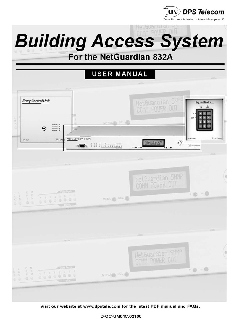
DPS NetGuardian 832A User manual

USER MANUAL
NetGuardian 832A/864A G5 ODOT
November 22 , 2016 D-UM-NETG5-12114 Firmware Version 5.3L
Visit our website at www.dpstelecom.com for the latest PDF manual and FAQs.

© 2016 DPS Telecom
This document contains proprietary information which is protected by copyright. All rights are reserved. No part of this
document may be photocopied without prior written consent of DPS Telecom.
All software and manuals are copyrighted by DPS Telecom. Said software and manuals may not be reproduced, copied,
transmitted or used to make a derivative work, by either mechanical, electronic or any other means in whole or in part, without
prior written consent fromDPS Telecom, except as required by United States copyright laws.
The materialin this manualis for information purposes and is subject to change without notice. DPS Telecomshall not be
liable for errors contained herein or consequential damages in connection with the furnishing, performance, or use of this
manual.
Revision History
November 22, 2016
April 13, 2016
March 24, 2016
June 1, 2015
Minor Updates
Added steps to set up Kenwood Radio
Keyed 202 Added
Initial ODOT Release

Contents
Visit our website at www.dpstelecom.com for the latest PDFmanual and FAQs
NetGuardian G5 Overview1 1
About This Manual2 2
Shipping List3 2
Port Allocation3.1 6
Optional Accessories4 6
Specifications5 10
Hardware Installation6 12
Tools Needed6.1 12
Mounting6.2 12
Power Connection6.3 13
LAN Connection6.4 15
Telco Connection6.5 17
Alarm and Control Relay Connections6.6 17
Alarm and Control Relay Connector Pinout Table (832A)6.6.1 18
Alarm and Control Relay Connector Pinout Table (864A)6.6.2 19
Discretes 1–24 Connector Pinout Diagram (832A)6.6.3 20
Analogs1–6/Discretes 25–32/Relays 1–8 Connector Pinout Diagram (832A)6.6.4 21
Discretes 1- 48 Connector Pinout Diagram (864A)6.6.5 22
Analogs 1-6/Discretes 49-64/Relays 1-8 Connector Pinout Diagram (864A)6.6.6 23
Analog Dipswitches6.6.7 24
Integrated Temperature and Battery Sensor (Optional)6.6.8 25
6.6.8.1 Analog Step Sizes 25
Data Ports6.7 26
Connecting NetGuardian Accessories6.7.1 27
GLD/ECU Expansion Port (RS-485)6.7.2 27
Hardware Options6.8 27
Integrated 10/100BaseT Ethernet Switch (Optional)6.8.1 28
Integrated T1/E1 Port6.8.2 28
GSM/GPRS or CDMA Wireless Modem Top Board (Optional)6.8.3 30
6.8.3.1 Wireless Modem Activation 30
+12 or +24 VDC Sensor Power Supply6.8.4 31
Hardware Acceleration (SSL/SSH)6.8.5 32
Integrated 8 Additional Serial Data Ports6.8.6 32
D-Wire Sensor Inputs6.8.7 33
6.8.7.1 Connecting D-Wire Sensors 33
Optional 66 Block Connector (832A)6.9 33

Optional 66 Block Connector (864A)6.10 36
Optional Hinged Wire-Wrap Back Panel6.11 38
Lexan Wire-Wrap Cover6.11.1 39
Optional Hinged Pluggable Back Panel6.12 40
Optional Hinged Amphenol Back Panel6.13 43
Alarm and Control Relay Connector Pinout Tables (KDA 864)6.13.1 46
Controls6.14 47
Bypassing Password6.15 48
LCD Display7 49
Alarm and Control Status Messages7.1 49
LCD Command Menu7.2 50
Sound off7.2.1 51
Reboot7.2.2 51
Run Config7.2.3 51
Contrast7.2.4 52
Alarm Speaker8 52
Front Panel LEDs9 53
Back Panel LEDs10 54
Configuring the NetGuardian11 55
RADIUS Authentication (Available as of Firmware 5.0I)11.1 55
Connecting to the NetGuardian12 55
... via Craft Port12.1 55
... via LAN12.2 57
TTY Interface13 58
Establishing an SSH Session13.1 59
Unit Configuration13.2 59
Ethernet Port Setup13.2.1 59
13.2.1.1 T1/E1 WAN Settings 60
13.2.1.2 New! Backup Mode 61
SFP Fiber Connection (For Fiber Build Option)13.2.2 61
Edit PPP Port13.2.3 62
Tune 202 Modem13.2.4 63
RADIUS Configuration13.2.5 64
UnitKal13.2.6 65
New! - TTY Command Mode13.2.7 65
DSCP Configuration13.2.8 68
Monitoring13.3 72
Monitoring the NetGuardian13.3.1 72
13.3.1.1 Monitoring Base Alarms 72

13.3.1.2 Monitoring Ping Targets 73
13.3.1.3 Monitoring and Operating Relays (Controls) 73
13.3.1.4 Monitoring Analogs 74
13.3.1.5 Monitoring System Alarms 74
13.3.1.6 Monitoring Data Port Activity 75
13.3.1.7 Monitoring the Accumulation Timer 75
13.3.1.8 Monitoring DSCP Devices 76
Viewing Live Target Pings13.3.2 77
Proxy Menu13.3.3 78
Event Logging13.3.4 78
Backing Up NetGuardian Configuration Data via FTP13.3.5 79
13.3.5.1 Reloading NetGuardian Configuration Data 79
Debug Input and Filter Options13.3.6 80
Reference Section14 81
Display Mapping14.1 81
System Alarms Display Map14.1.1 84
SNMP Manager Functions14.2 88
SNMP Granular Trap Packets14.3 89
Trap SNMP Logic14.4 91
ASCII Conversion14.5 91
RADIUS Dictionary File (Available on Resource Disk)14.6 92
Frequently Asked Questions15 93
General FAQs15.1 93
SNMP FAQs15.2 95
Pager FAQs15.3 96
Technical Support16 97
End User License Agreement17 98

1
NetGuardian G5 Overview1
Fig. 1.1. The NetGuardian has all the tools you need to manage your remote site.
The NetGuardian G5 — The Intelligent RTU for Complete Site Management
The NetGuardian G5 is a RoHS 5/6-compliant, LAN-based, SNMP/DCPx remote telemetry unit. The
NetGuardian has all the tools you need to manage your remote sites, including built-in alarm monitoring,
paging and email capabilities that can eliminate the need for an alarm master.
With the NetGuardian, you can:
·Monitor 32 discrete alarms, 32 ping alarms, and 8 analog alarms
·Control remote site equipment via 8 terminal server ports and 8 control relays
·Monitor your remote site from anywhere using the NetGuardian's built-in Web Browser Interface.
·Report alarms to multiple SNMP managers or the T/Mon NOC Alarm Monitoring System.
·Report alarms via LAN or dial-up connection.
·Automatically send pager and email alarm notifications 24/7.
·Connect multiple concurrent users via Telnet over LANto telecom switches, servers, radios,
PBXs and other equipment.
·Monitor discrete and analog threshold alarms.
·Ping IP network devices and verify that they're online and operating.
·NEW! Backup Mode: Redundant LANconnectivity.
New: The NetGuardian G5 supports serial baud rates up to 115,200, additional RS485 for GLD/ECU
expansion polling port, triple CPUspeed for faster processing, optional built-in 4-port switch (tied to
NET2), optional external temperature sensor, analog readings accurate to within +/- 1%, dual 10/100
NICs (isolated) replacing the 10BaseT NICs, SNMPv2c, SNMPv2c Inform trap, and SNMPv3.
TIP: This is the basic installation (hardware) manual. For software and web configuration manuals,
please refer to appropriate manual on the Resource CD provided with your unit, visit www.dpstele.com/
pdfs/op_guides
Stand-alone local visibility
You don't need an alarm master unit to monitor your site with the NetGuardian. With the NetGuardian's
built-in Web Browser Interface, you can access the NetGuardian, view alarms and control remote site
devices from any computer anywhere in your network.
24/7 pager and email alerts - no master needed
Out of the box, the NetGuardian supports 24/7 pager and email reporting. Send alarms directly to
maintenance technicians in the field, even when no one's in the office.
Connect via LAN to telecomswitches, servers, radios and more
Each of the NetGuardian's eight serial ports can be individually configured to serve as a craft port, a
channel port or a TCP or UDP reach-through port, giving you LAN-based terminal server access to up to
eight serial devices.

2
NEW - RADIUS Authentication (As of firmware v5.0I)
Take the security of your alarm remotes to the next level with RADIUS authentication. Now the
NetGuardianG5 can interact withyour RADIUS server, integrating it as part of your enterprise
management.
Reports to multiple SNMP managers and T/Mon NOC simultaneously
The NetGuardian reports to both the T/Mon NOC Alarm Monitoring System and any SNMP manager.
You can simultaneously forward alarms from the NetGuardian to T/Mon NOC and multiple SNMP
managers at multiple IP addresses. Alarms can also be configured to dispatch to one, some, or all
SNMP managers.
Fig. 1.2. Your NetGuardian will come with a label on the front panel that will include the Product Number,
Serial Number, and MAC Addresses. This will help you if you ever need to contact DPS about your
device. The barcode and serial number can be used to faciliate your internal tracking.
About This Manual2
There are three separate user manuals for the NetGuardian G5: the Hardware Manual (which you're
reading now), the NGEditG5 User Manual, and the NetGuardian G5 Web Interface User Manual.
This Hardware Manual provides instructions for hardware installation and using the TTYinterface. The
NGEditG5 and Web Interface User Manuals, included on the NetGuardian Resource CD, provide
instructions for configuring the NetGuardian using the Windows-based NGEditG5 utility software or the
Web Interface.
Shipping List3
While unpacking the NetGuardian, please make sure that allof the following items are included. If some parts are
missing, or if you ever need to order new parts, please refer to the part numbers listed and call DPS Telecom at
(800) 622-3314.
NetGuardian 832AG5: D-PK-NETG5-12001 NetGuardian G5 Hardware
NetGuardian 864AG5: D-PK-NG864-12001 Manual D-UM-NETG5

3
NetGuardian G5 Resource CD DB9M-DB9F Download Cable 6 ft.
(includes manuals, MIBs, and software) D-PR-045-10-A-04
Two Ethernet Cables 14 ft. Telephone Cable 6 ft.
D-PR-923-10B-14 D-PR-045-10A-01
23" Rack Ears 19" Rack Ears
D-CS-325-10A-01 D-CS-325-10A-00
Eight 3/8" Ear Screws (F) Four Standard Rack Screws (H)
2-000-60375-05 1-000-12500-06
Four Metric Rack Screws (G) Three 3/4-Amp GMT Fuses (B)
2-000-80750-03 2-741-00750-00
Two Large Power Connector Plugs for Main Power (C) Four Cable Ties
2-820-00862-02 (Sixteen with hinged panel)
4 Pin Analog Connector (D) Pads (E)
2-820-00814-02 2-015-00030-00
A B C D E F G H Optional
+
Screws and connectors are packaged in a sealed hardware kit, shown above
+

4
(Hardware kit containing a WAGO connector)

5
Optional Items
Two 3/4-Amp GMT AccessoryFuses (A) One Small Connector for Sensor Output
2-741-00250-00 2-820-00812-02
External Temperature Sensor 20 ft. External Temperature Sensor
D-PR-991-10A-07 D-PK-SENSR-12037

6
Port Allocation3.1
Located on the top of the unit in the back left corner is the Port Allocation Sticker. This sticker includes
your part number (D-PK-NETG5-#####.#####), which specifies your build option. The table below it lists
your port allocation. This label displays serial electrical information about each of the ports, for example
if the port hardware is configured for RS232, RS485, 202, etc.
Optional Accessories4
You can extend the capabilities of the NetGuardian through accessory units that provide greater discrete
alarm capacity, remote audiovisual alarm notification, visual surveillance of remote sites, and other
options. If you would like to order any of these accessories, or if you would like more information about
them, call DPS Telecom at (800) 622-3314.
NetGuardian Expansion (NetGuardian 832A/864ADX G5)
D-PK-DX832/D-PK-DX864
The NetGuardian G5 expansions provide and additional 32 alarms for your NetGuardian 832Amodel or
64 points for your 864A, providing a total of 128 or 256 alarms with 3 expansion units. Each expansion
comes standard with an additional 8 control relays and 8 analog inputs, and is available with an optional
8 port hub. (Optional builds are also available without controls, analogs, or both.)
NetGuardian Expansion (NetGuardian DX G4)
D-PK-NETDX-12022.00001
The NetGuardian Expansion G4 provides an additional 48 discrete and 8 relay controls. Up to three
NetGuardian Expansions can be daisy-chained off one NetGuardian, providing a total of 176 discrete

7
and 32 analog alarm points.
NetGuardian Expansion
The NetGuardian 480 (NG480) Expansion provides an additional 80 alarms and 4 relays. With 80
discrete alarm inputs, you can easily forward all the alarms of a small to medium-sized site.
NetGuardian E16
D-PK-DXE16
Adding the NetGuardian E16 provides an additional 16 alarm points and 16 controls. One NetGuardian
E16 unit may be used per NetGuardian 832A/864AG5 remote. In this configuration, the E16 must be the
last unit in the chain. Having only 1 serial port, it cannot forward traffic to a subsequent RTU.
General LCD Display(GLD)
D-PK-GLDRJ-12001.00001
The General LCD Display (GLD) is a small wall-mounted remote terminal for the NetGuardian. The LCD
display shows system status and alarm messages, and the built-in speaker gives an audible notice of
alarms. Up to 12 GLDs can be daisy-chained off the NetGuardian.
NetGuardian SiteMON IP D-PK-CAMRA
The NetGuardian SiteMON provides security surveillance of remote sites. The SiteMONconnects to
either the NetGuardian's integrated 10/100BaseT switch or a separate 10/100/1000 switch. SiteMON
images can be accessed directly from the SiteMON's Web Browser Interface or T/GFX. You can also
mount the camera at harsh weather sites with the wide-temp chassis design.

8
Hinged Wire-Wrap Back Panel
For 19" rack: D-PK-NGPAN-12002 For 23" rack: D-PK-NGPAN-12006
The hinged wire-wrap back panel provides wire-wrap connections for the NetGuardian's alarms and
control relays.
Pluggable Barrier Panel
For 19" rack: D-PK-NGPAN-12021 For 23" rack: D-PK-NGPAN-12007
The pluggable barrier panel provides screw-lug barrier plug connections for the NetGuardian's alarms
and control relays.
Hinged Amphenol Back Panel
For 19" rack: D-PK-NGPAN-12027
The Hinged AmphenolBack Panel easilyallows for Upgrades from a KDA864 to a NetGuardian
864.
NetGuardian 3288 Test Fixture
D-PK-TSTBX-12005.00001

9
Every DPS product is rigorously tested before shipping, and the NetGuardian Test Box allows
technicians to verify every discrete alarm input, control relay, and voltage-based analog alarm input on a
NetGuardian G5. This time-tested tool is now available to you as the NetGuardian 3288 Test Fixture
(known casually as the "NetGuardian Test Box"). With 32 discrete alarm toggles, 8 analog knobs, and 8
control relay LEDs, you can verify every alarm input and control output on your NetGuardians in a
controlled way.

10
Specifications5
Discrete AlarmInputs: 32 (expandable to 80, 128, or 176 in G5 model)
64 (expandable to 112, 160, or 208 in 864Amodel)
Analog Alarms: 8
Analog Input Range: (–94 to 94 VDC or 4 to 20 mA)
Analog Accuracy: +/- 1% of Analog Range (See Analog Step Sizes)
Control Relays: 8 Form C (expandable to 16, 24, 32)
MaximumVoltage: 60 VDC/120 VAC
MaximumCurrent: 1 Amp, AC/DC
Ping Alarms: 32
Protocols: SNMPv1, SNMPv2c, SNMPv3, DCPx, DCPf, TRIP, SNPP
SMTP, TAP, HTTP, FTP, TELNET, ICMP, RADIUS, (SSH, HTTPS
with Hardware Acceleration build option).
Interfaces: 9 RJ45 Yost serial ports (17 RJ45 ports with the 16S top board
option) 2 RJ45 10/100 full-duplex Ethernet ports (1 port tied internally to
switch - if switch option is purchased)
1 RJ11 telco jack
2 50-pin amphenol connectors (discretes, controls, and analogs)
1 4-pin screw connector (analogs)
With Fiber top-board build option: 4 10/100/1000 copper Ethernet
ports AND 2- 1000 Base-X SFP Fiber ports
With D-Wire top-board build option: 1 RJ11 D-Wire port
With WAN top-board build option:1 Rj45 WAN port
Physical Dimensions: 1.720"H x 17.026"W x 8.136"D (NetGuardian 832A)
(11.250"D with hinged Wire Wrap Adapter)
1.720"H x 17.026"W x 9.636"D (NetGuardian 864A)
(12.750"D with hinged Wire Wrap Adapter)
Weight: 4 lbs. 3 oz. (1.9 kg)
Mounting: 19" or 23" rack
Power Input
Voltage Options Include: –48 VDC nominal (–36 to –72 VDC)
(Optional) –24 VDC nominal (–18 to –36 VDC)
(Optional) Wide Range –24/–48 VDC (–18 to –58 VDC)
(Optional) +24VDC (+18 to +36 VDC)
(Optional) +12VDC (+11 to +18 VDC)
Current Draw: 300 mAat 48 VDC (1 600 mA at 24 VDC)
GMT Fuse: 3/4 amp recommended
Sensor Power Output
Voltage Output Options: +12 VDC

11
+24 VDC
Output Current: Up to 250 mAat either +12 or +24 VDC
Input Current Draw:May increase by 150 mAat 48 VDC
GMT Fuse: 3/4 amp recommended
Modem: 33.6 K internal
Visual Interface: LCD display
16 bicolor LEDs
5 unicolor LEDs (10 with Switch Option)
Audible Notification: Alarm speaker
Operating Temperature: 32° to 140° F (0° to 60° C)
Storage Temperature: -22° to 176° F (-30° to 80° C)
Industrial Temperature Option: -22° to 158° F (-30° to 70° C)
Operating Humidity: 0%–95% noncondensing
MTBF: 60 years
Windows Compatibility: Windows 95, 98, NT, ME, XP, 2000, Vista, 7 32/64 bit
*RoHS 5 Approved
Note: This equipment has been tested and found to comply with the limits for a Class Adigital device,
pursuant to part 15 of the FCC Rules. These limits are designed to provide reasonable protection
against harmful interference when the equipment is operated in a commercial environment. This
equipment generates, uses, and can radiate radio frequency energy and, if not installed and used in
accordance with the instruction manual, may cause harmful interference to radio communications.
Operation of this equipment in a residential area is likely to cause harmful interference in which case the
user will be required to correct the interference at his own expense.

12
Hardware Installation6
Tools Needed6.1
To install the NetGuardian, you'll need the following tools:
Phillips No. 2 Screwdriver Small Standard No. 2 Screwdriver
Wire Strippers/Cutter Wire Wrap Gun (if hinged wire wrap panel is
used)
Punch Down Tool (if 66 blocks are used) PC with NGEditG5 software
Mounting6.2
Fig. 6.2.1. The NetGuardian can be flush or rear-mounted
The NetGuardian mounts in a 19" rack or a 23" rack using the provided rack ears for each size. Two
rack ear locations are provided. Attach the appropriate rack ears in the flush-mount or rear-mount
locations shown in Figure 6.2.1.
Note: Rack ears can be rotated 90° for wall mounting or 180º for other mounting options (not shown).

13
Power Connection6.3
Fig. 6.3.1. Power connectors and fuse.
The NetGuardian has two screw terminal barrier plug power connectors, located on the left side of the
back panel. (See Figure 6.3.1.)
WARNING!
The Grounding Lug on the back of the unit provides a permanent connection to
earth ground when connected. The Grounding Lug must be used in order to
complywith standards.
Grounding Lug and Symbol
Before you connect a power supplyto the NetGuardian, test the voltage of your power supply:
·Connect the black common lead of a voltmeter to the ground terminal of the battery, and connect
the red lead of the voltmeter to the battery's –48 VDC terminal. The voltmeter should read
between -36 and –72 VDC. If the reading is outside this range, test the power supply.
·If your NetGuardian has the -24 VDC power connection option, then the voltmeter should read
between -18 and -36 VDC.
·If your NetGuardian has the +12 VDC power connection option, then the voltometer should read
between +11 and +18 VDC.
To connect the NetGuardian to a power supply, follow these steps:
1. Remove the fuse from the back panel of the NetGuardian. Do not reinsert the fuse until all
connections to the unit have been made.
2. Remove the power connector plug from Power Connector A. Note that the plug can be inserted
into the power connector only one way - this ensures that the barrier plug can only be reinserted
with the correct polarity.
Note:that the –48V terminal is on the left and the GND terminal is on the right.
3. Use the grounding lug to connect the unit to earth ground. The grounding lug is next to the
symbol. Insert the eyelet of the earth ground cable between the two bolts on the grounding lug
(Ground cable not included).
4. Insert a batteryground into the power connector plug's right terminal and tighten the screw
5. Insert a –48 VDC line to the plug's left terminal and tighten its screw.

14
6. Push the power connector plug firmly back into the power connector. If the power feed is
connected correctly, the LED by the connector will light GREEN. If the polarity of the power feed
is reversed, the LED will not illuminate.
7. Repeat Steps 2–4 for Power Connector B.
8. Reinsert the fuse to power the NetGuardian. The front panel LEDs will flash RED and GREEN.
To connect the NetGuardian to a power supplyusing a WAGO connector, follow these steps:
WARNING!
The Grounding Lug on the back of the unit provides a permanent connection to
earth ground when connected. The Grounding Lug must be used in order to
complywith standards.
Grounding Lug and Symbol
1. Remove the 2fuses (A& B) from the back panel of the NetGuardian. Do not reinsert the fuses until
all connections to the unit have been made.
2. Remove the WAGO power connector. Note that the plug can be inserted into the power connector
only one way — this ensures that the barrier plug can only be reinserted with the correct polarity. Note
that the –48Vterminal is on Slots 1 and 3 and the GND terminal is on Slots 2 and 4 when counting
from left to right.
3. Use the grounding lug to connect the unit to earth ground. The grounding lug is next to the
symbol.Insert the eyelet of the earth ground cable between the two bolts on the grounding lug (Ground
cable not included).
4. Insert a batteryground into the power connector plug's slots 2 and 4 by pushing down on top of the
appropriate slot of the WAGO connector with a screwdriver and inserting the wire into the slot, then
releasing the screwdriver. Insert a –48 VDC line to the plug's slots 1 and 3 using the same method as
before.

15
Inserting a -48 VDC Line into Slot
1 of WAGO Connector
5. Push the power connector plug firmly back into the power connector. If the power feed is connected
correctly, the LED by the connector will light GREEN. If the polarity of the power feed is reversed, the
LED will not illuminate.
6. Reinsert the fuses to power the NetGuardian. The front panel LEDs will flash RED and GREEN.
LAN Connection6.4
Fig. 6.4.1. Two 10/100 Ethernet ports (With Switch)
Fig. 6.4.2. Two 10/100 Ethernet ports (Without Switch)
RJ45 Ethernet Connection
8
7
5
6 Receive In –(RI–)
4
3 Receive In +(RI+)
2 Transmit Out –(TO–)
1 Transmit Out + (TO+)
Fig. 6.4.3 Ethernet port pinout
For enhanced security, the NetGuardian G5 has two 10/100 Ethernet ports. Each port has its own
separate IP address and subnet, so you can safely connect one port to your private company LAN and
the other to the public Internet.
There is no routing between Net 1 and Net 2, this ensures that both connections are independent of
each other. By default, outbound data traffic from the NetGuardian 832Awill be sent over Net 2. Only
outbound data that is specifically directed to Net 1, usually the Company's LAN, will be sent to Net 1. To
use both network interfaces, be sure Net1 and Net2 are on separate Subnet Masks.
To use only one of the network interfaces, set either Net1 or Net2 to IP address being used and set the
unused network IP subnet and gateway to 255.255.255.0. If your NetGuardian has the 4-port hub build
option, use Net2, which is connected to the Hub. Both ports are standard RJ45 ports that take standard
RJ45 Ethernet cables. If the IP connection is OK, the LNK LED will light SOLID GREEN when the cable
is connected.
Other manuals for NetGuardian 832A
1
This manual suits for next models
1
Table of contents
Other DPS Security System manuals
Popular Security System manuals by other brands

Telefire
Telefire ADR-3000 System introduction

nVent SCHROFF
nVent SCHROFF 21596-077 user manual

2gig Technologies
2gig Technologies Go!Control Panel user guide

Carel
Carel BADGE MESSENGER SRX manual

Mircom
Mircom Fire-Link NMC-100 Series Installation and operation manual

Momentum
Momentum Aria quick start guide