Dräger PAS MAC1000 User manual

MOBILE BREATHING-AIR
COMPRESSOR
PAS MAC1000
OPERATOR’S HANDBOOK
Draeger Safety UK Ltd
Ullwater Close, Kitty Brewster Industrial Estate,
Blyth, Northumberland, NE24 4RG, UK
Tel No: +44 (0) 1670 352891
Fax No: +44 (0) 1670 356266
E‐mail:[email protected]
Website:www.draeger.ltd.uk

CONTENTS
Page
1 INTRODUCTION 1
2 GENERAL ARRANGEMENT
2.1 PAS:MAC1000 On Site 1
2.2 Compressor 2
2.3 Breathing-Air Components 2
3 TECHNICAL DATA
3.1 Compressor 3
4 OPERATING INSTRUCTIONS
4.1 Safety Precautions 4
4.2 Siting 4
4.3 Pre-operation Checks 4-5
4.4 Starting Instructions 5
4.5 Stopping Instructions 5
5 SERVICE
5.1 Before Working on the Compressor 6
5.2 Preventive Maintenance Schedule for the
Compressor 6
5.3 BA Filtration 7
5.4 Unloader Check Valve 8-9
6 SPARES
6.1 Standard Components 10
6.2 Service Spares 10
7 DRAWINGS
7.1 GA Drawing 11
7.2 Pneumatic Circuit 12
7.3 Electrical Circuit 13
8 CERTIFICATE OF CONFORMITY 14

PAS:MAC 1000 - 1 - OCTOBER 2010
INTRODUCTION
The PAS:MAC 1000 portable compressor set is designed to
deliver breathing quality air suitable for one man wearing air-fed
respiratory protective equipment.
A 230V/1.5kW electric motor driving a ‘V’ configuration twin
cylinder, reciprocating compressor, provides air which, after
processing, is purified to breathing quality conforming to EN 12021
(within certain environmental limitations). The compressor unit is
mounted within a tubular steel loop frame.
2.0 GENERAL ARRANGEMENT
2.1 PAS:MAC 1000 on site showing the unloader/check valve, power
supply lead and starter.

PAS:MAC 1000 - 2 - OCTOBER 2010
2.2 ATLAS COPCO LE15-10-S COMPRESSOR
2.3 BREATHING-AIR COMPONENTS
1 Outlet pressure gauge
2 Breathing-air outlet coupling
3 Pre-filter
4 Main coalescing oil removal filter
5 Activated carbon filter
6 Membrane dryer
7 Lockable outlet pressure regulator
3.0 TECHNICAL DATA

PAS:MAC 1000 - 3 - OCTOBER 2010
3.1 COMPRESSOR
The compressor is a lubricated, twin cylinder, single stage
reciprocating unit; air is drawn through an air filter mounted in
between the cylinders. After compression the air passes through
an unloader/check valve, an aftercooler and finally a pulsation
vessel mounted under the unit before passing through a set of
filters to provide air of breathable quality.
Model Atlas Copco LE15-10-S
Nominal Operating Speed 1500 rpm
Oil Grade Atlas Copco PAO oil
Maximum Working Pressure 10 bar
Oil Capacity 0.8 litres
Free Air Delivered (FAD) 3.4 l/sec (7.2 cfm @ 7 bar at
Normal Temperature & Pressure
[NTP])
Electric Motor 1.5kW TEFV
Supply Voltage 230V 50 Hz 1ph
Dimensions
Length 980 mm
Width 586 mm
Height 770 mm
Weight 115 kgs
Outlets One CEJN (other safety lock
types available)

PAS:MAC 1000 - 4 - OCTOBER 2010
4.0 OPERATING INSTRUCTIONS
4.1 SAFETY PRECAUTIONS
In addition to normal safety rules which should be observed with
stationary air compressors and equipment, the following safety
directions and precautions are of special importance.
When operating this unit, the operator must employ safe working
practices and observe all related local work safety requirements
and ordinances.
The owner is responsible for maintaining the unit in a safe
operating condition. Parts and accessories shall be replaced if
unsuitable for safe operation.
Installation, operation, maintenance and repair shall only be
performed by authorised, trained, competent personnel.
Never remove or tamper with the safety devices, guards or
insulations fitted on the unit.
4.2 SITING
Position the compressor on firm, level ground.
Site in a well-ventilated area well away from any source of
hazardous gas, dust or vapour so that any contamination created
by the work to be undertaken does not drift towards the
compressor.
WARNING: The breathing-air filtration will not remove carbon
monoxide or carbon dioxide, therefore position the compressor
well away from any potential vehicle exhaust contamination.
4.3 PRE-OPERATION CHECKS
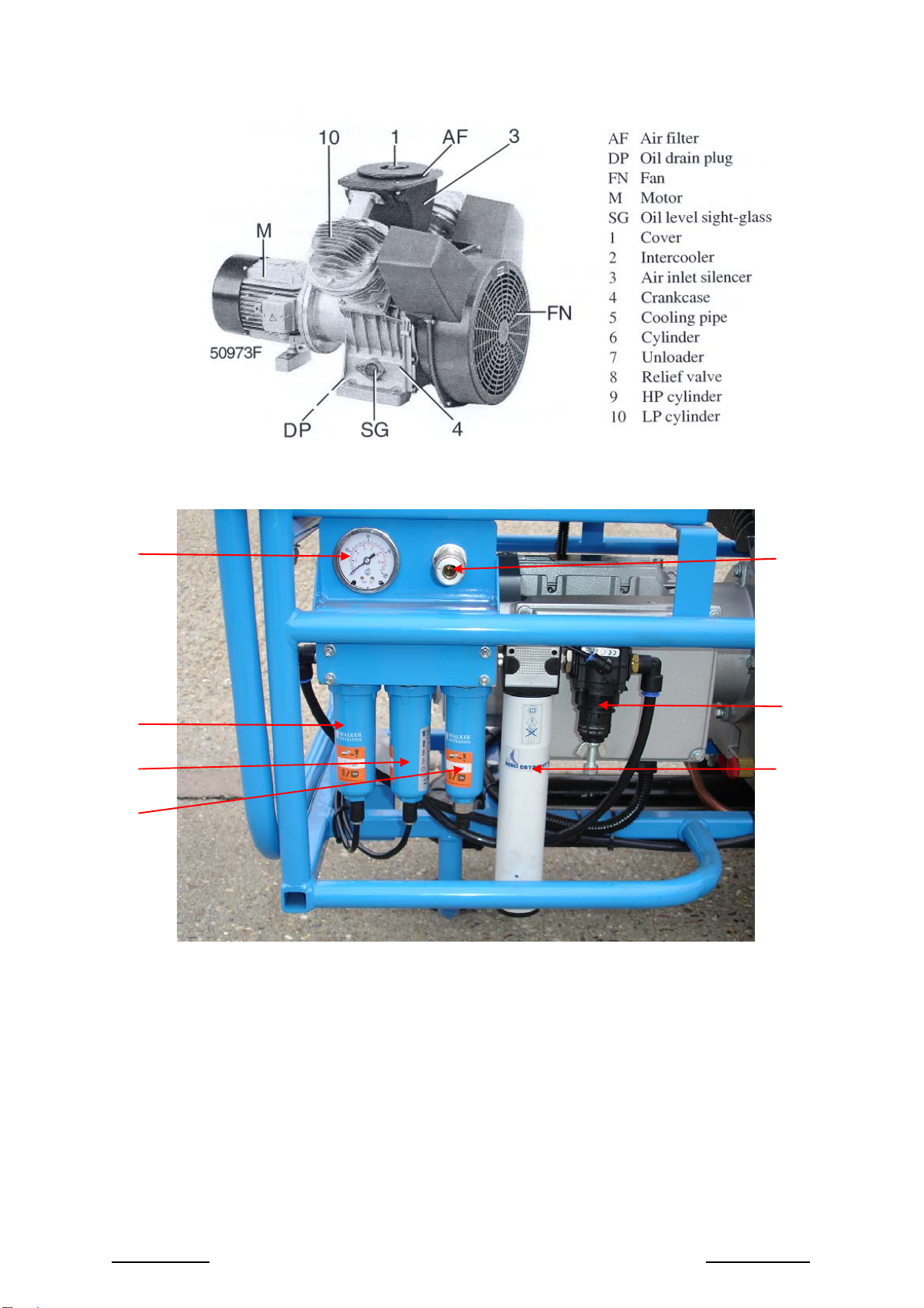
Check the compressor’s oil level which must be near the top of the
red circle of the sight glass. The minimum level is the lower part of
the red circle.
Top up, if necessary, by slowly unscrewing the filler cap. If there is
any escape of oil/air DO NOT CONTINUE REMOVING THE CAP
UNTIL ALL PRESSURE IS RELEASED. (The filler cap is located
between the cylinders on top of the compressor casing.)

PAS:MAC 1000 - 5 - OCTOBER 2010
Electrical cable - visually inspect cable and plug for
damage. Statutory insulation
inspections may be required – see local
rules.
Note:Electric cable and plug can be stowed within the tool box.
Ensure cable is run through the cut-out in the front of the box
when in use.
Aftercooler - visually inspect for damage/leaks.
Running up checks - start compressor and check for leaks.
Compressor pressure should be 8.5 bar.
Outlet pressure maybe adjusted using
the regulator fitted.
Condensate - check condensate collection bottle.
Note: Dispose of collected condensate
in an environmentally safe way.
4.4 STARTING INSTRUCTIONS
Plug into a 230 volt single phase power supply and press the
green starter button.
4.5 STOPPING INSTRUCTIONS
Ensure the machine is not supporting life before pressing the red
stop button.

PAS:MAC 1000 - 6 - OCTOBER 2010
5.0 SERVICE
5.1 BEFORE WORKING ON THE COMPRESSOR
Potentially lethal voltages are used to power this machine.
Disconnect power lead from mains supply prior to carrying out any
service work.
Do not undertake any work until the compressor and pulsation
vessel have been relieved of all pressure.
Wait until the compressor’s vent down cycle is complete.
Release any pressure contained in the aftercooler or associated
pipework.
Check that the air-end pressure gauge reads zero. Do not
proceed until it does.
5.2 PREVENTIVE MAINTENANCE SCHEDULE FOR THE COMPRESSOR
The schedule contains a summary of the maintenance instructions.
When servicing, replace all disengaged packings, eg gaskets, ‘O’
rings, washers.
The “longer interval” checks must also include the “shorter
interval” checks.
MAC1000 Service Schedule
Service Interval
Annually
Service Operation Note Daily Annually
500 hrs 6 months
1000 hrs 1000
hrs 2000
hrs
Check compressor’s oil level 1
Check/clean compressor’s air intake filter 3
Check/empty condensate collection bottle
Check electrical connections are tight
Change compressor oil
Change compressor’s air intake filter
Change breathing-air pre-filter element
Change breathing-air main (coalescing) filter
element
Change breathing-air activated carbon filter
element
Test safety valve 2
Notes: 1 Maintain the oil level in the red circle of the sight glass.
2 Wear gloves and safety glasses.
3 For normal operation in clean surroundings, more
frequently when operating in a dusty environment.

PAS:MAC 1000 - 7 - OCTOBER 2010
5.3 BREATHING-AIR FILTRATION
Item Description Part NoService Interval
1 Pre-filter element FIL 0471 2000 hours/12 months
2 Main coalescing filter element FIL 0473 2000 hours/12 months
3 Activated carbon filter element FIL 0475 1000 hours/ 6months

PAS:MAC 1000 - 8 - OCTOBER 2010
5.4 UNLOADER CHECK VALVE
OPERATION
The Mark II maintains air vessel pressure levels between a “cut-
out” pressure level and a “cut-in” pressure level. The difference
between the two is known as the “differential”. The Mark II senses
air pressure through a small orifice in the side of the OUT port of
the valve.
At low pressure levels, all compressor discharge air passes
through the Mark II into the air vessel. When the vessel pressure
reaches the desired cut-out pressure, the VENT port on the Mark II
opens and allows all compressor discharge air to be vented to
atmosphere through the VENT port. At the same time, a check
valve internal to the Mark II closes and prevents any stored air
from being vented out of the VENT port.
As air is used the the air vessel the pressure drops and, at the
desired cut-in pressure, the valve changes back to its original
configuration where all compressor discharge air is flowing through
the valve into the air storage vessel. This cycle continues,
therefore maintaining stored pressure levels between the cut-out
and cut-in levels.

PAS:MAC 1000 - 9 - OCTOBER 2010
REGULATOR ADJUSTMENT
Cut-out pressures are adjustable from 60 psi to 250 psi with the
standard silver spring. The differential (difference between cut-out
and cut-in pressures) is typically set at the factory at about 15% of
the cut-out pressure. This is usually a suitable differential and will
not normally need to be readjusted.
Adjustment procedure:
1 Loosen only locknut.
2 Turn adjusting screwclockwise to raise cut-out and cut-in
pressure levels and counterclockwise to decrease cut-out and
cut-in pressure levels.
3 Start compressor and note cut-out and cut-in pressures. Make
adjustments as necessary using screwand, when acceptable,
tighten locknut.
4 Adjust the cut-in pressure to the desired level per steps 1
through 3, above.
5 Looses locknutand turn adjustment screwclockwise to raise
cut-out pressure and counterclockwise to decrease cut-out
pressure. Tighten locknut when desired cut-out pressure is set.
Since step 5 should not change the desired cut-in pressure set
in step 4, adjustment is now complete.

PAS:MAC 1000 - 10 - OCTOBER 2010
6.0 SPARES
6.1 STANDARD COMPONENTS
Description Factair Part NoQty
Compressor and motor assembly COM 0186 1
Pressure control device VAL 0169 1
Aftercooler cooling tubes COO 0082 2
Pressure relief valve 12 bar VAL 0178 1
Pulsation vessel FAB 0154 1
Pre-filter complete FIL 0470 1
Main coalescing filter complete FIL 0472 1
Activated carbon filter complete FIL 0474 1
Membrane dryer DRY 0015 1
Outlet pressure regulator FIL 0308 1
Outlet pressure gauge IND 0100 1
Breathing-air outlet coupling FIT 0692 1
Condensate bottle BOT 0001 1
Wheels WHE 0012 2
Control enclosure and circuit breaker ELE 2214 + ELE 2215 1
Hourmeter ELE 0616 1
Rubber foot AVM 0004 1
6.2 SERVICE SPARES
Description Factair Part No
Pre-filter element FIL 0471
Main coalescing filter element FIL 0473
Autodrain – pre and main filter DRA 0019
Activated carbon filter element FIL 0475
Semi-automatic drain – activated carbon filter DRA 0020
Outlet pressure regulator – service kit KIT 0027
Compressor air intake filter element KIT 0018
Compressor PAO oil – 1 litre can OIL 0013
Compressor PAO oil – 5-litre can OIL 0015
Compressor valve kit KIT 0019
Compressor piston rings and cylinders KIT 0020
Compressor piston rings only KIT 0021

PAS:MAC 1000 - 11 - OCTOBER 2010
7.0 DRAWINGS
7.1 GA DRAWING

PAS:MAC 1000 - 12 - OCTOBER 2010
7.2 PNEUMATIC CIRCUIT

PAS:MAC 1000 - 13 - OCTOBER 2010
7.3 ELECTRIC CIRCUIT

PAS:MAC 1000 - 14 - OCTOBER 2010
8.0 CERTIFICATE OF CONFORMITY
DECLARATION OF CONFORMITY
73/23/EEC [known as ‘Low Voltage Equipment (LVD)’]
2006/42/EC [known as ‘Machinery Directive’]
2000/14/EC [known as ‘Noise Emission in the Environment
Directive’ – Annex VIII]*
*Notified body:-
LRQA Ltd, Hiramford, Middlemarch Office Village, Siskin Drive,
Coventry, CV3 4FJ
WeFactair Declare that under our sole
responsibility for supply/
manufacture of this product
Machine Type: Mobile Breathing-air Compressor
Model No: PAS:MAC 1000
Serial No:
Guaranteed Sound Power Level Measured Sound Power Level
99 dB LWA 94.5 dBLWA
to which this declaration relates
is in conformity with the
essential Health and Safety
Requirements identified in the
above Directives. (Technical
documentation held at the above address by
Stuart Harris, Technical Services Manager.)
Kevin Ball
(name and signature/mark of authorised person)
Date: En
g
ineerin
g
Mana
g
er
(position)
Table of contents
Other Dräger Air Compressor manuals
Popular Air Compressor manuals by other brands

Hitachi Koki
Hitachi Koki EC 189 Instruction manual and safety instructions

RIDGID
RIDGID OF50150TS Mobilair Replacement instructions

Atlas Copco
Atlas Copco PNS 1250 Cud S3A/T3 APP instruction manual

Stanley
Stanley AIRPRO 120 CDC120SCA instruction manual

Champion
Champion CCE10 Operation maintenance manual & parts list

Schneider Airsystems
Schneider Airsystems UNM STB 1000-10-10 Original operating manual