Dräger PAS MAC4000 Service manual

MOBILE BREATHING-AIR
COMPRESSOR
PAS MAC4000
(Incorporating pressure swing dryer
and CO + CO2suppression)
OPERATOR’S HANDBOOK
Draeger Safety UK Ltd
Ullwater Close, Kitty Brewster Industrial Estate,
Blyth, Northumberland, NE24 4RG, UK
Tel No: +44 (0) 1670 352891
Fax No: +44 (0) 1670 356266
E‐mail:[email protected]
Website:www.draeger.ltd.uk

CONTENTS
Section Page
1.0 INTRODUCTION 1
2.0 GENERAL ARRANGEMENT
2.1 PAS:MAC4000 ON SITE 2
2.2 INSTRUMENT PANEL AND GAUGES/OUTLETS 3
2.3 GENERAL INFORMATION 4
3.0 SAFETY PRECAUTIONS – GENERAL 5
4.0 OPERATING INSTRUCTIONS
4.1 SITING 6
4.2 PRE-OPERATION DAILY CHECKS 6
4.3 TOWING THE COMPRESSOR 6
4.4 START UP PROCEDURE 7
4.5 SHUTDOWN PROCEDURE 7 - 8
5.0 WARNING SEQUENCES 9 -10
6.0 MAINTENANCE
6.1 QUICK REFERENCE – SERVICE SCHEDULE 11-12
6.2 COMPRESSOR 13-15
6.3 ENGINE 16-20
6.4 APPROVED OILS 21
6.5 OVERTEMPERATURE SHUTDOWN 22
6.6 BA FILTRATION 23
6.7 CHALWYN VALVE 24-26
6.8 PRESSURE SWING ADSORPTION DRYER 27-29
7.0 DRAWINGS
7.1 PNEUMATIC
7.2 ELECTRICAL

PAS:MAC4000 - 1 - MAY 2010
1.0 INTRODUCTION
Draegerprovides a rangeofbreathing-airsystems which are completely
self-contained, fully mobile and specially designed to deliver breathing
quality compressed air to operatives wearing air-fed respiratory
equipment when working in hazardous atmospheres such as occur in
the nuclear, petrochemical, pharmaceutical and other industries. The
systems provide breathable air conforming EN 12021.
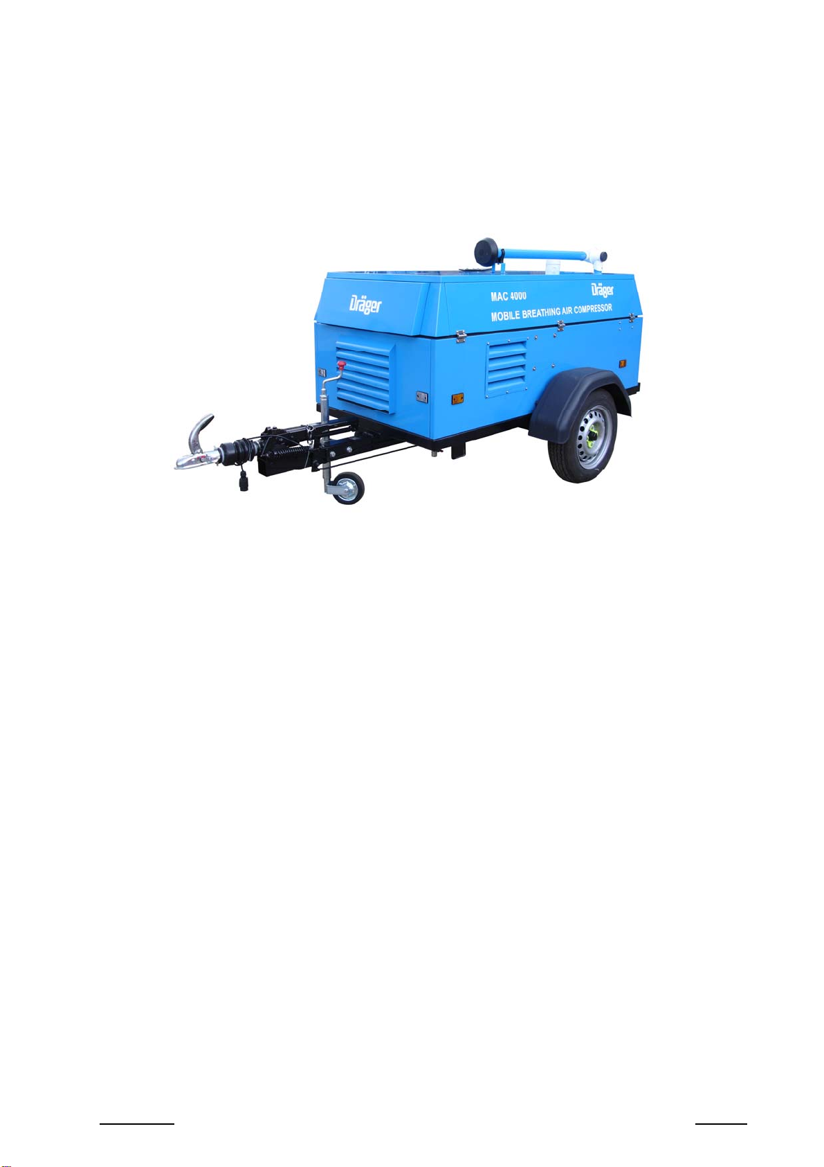
The MAC4000 is a fast towing unit with a three-cylinder, water-cooled
diesel engine, driving a rotary vane compressor mounted on a
subframe. A fully automatic back-up system is incorporated which
maintains the air supply from reserves stored in three 9-litre cylinders.
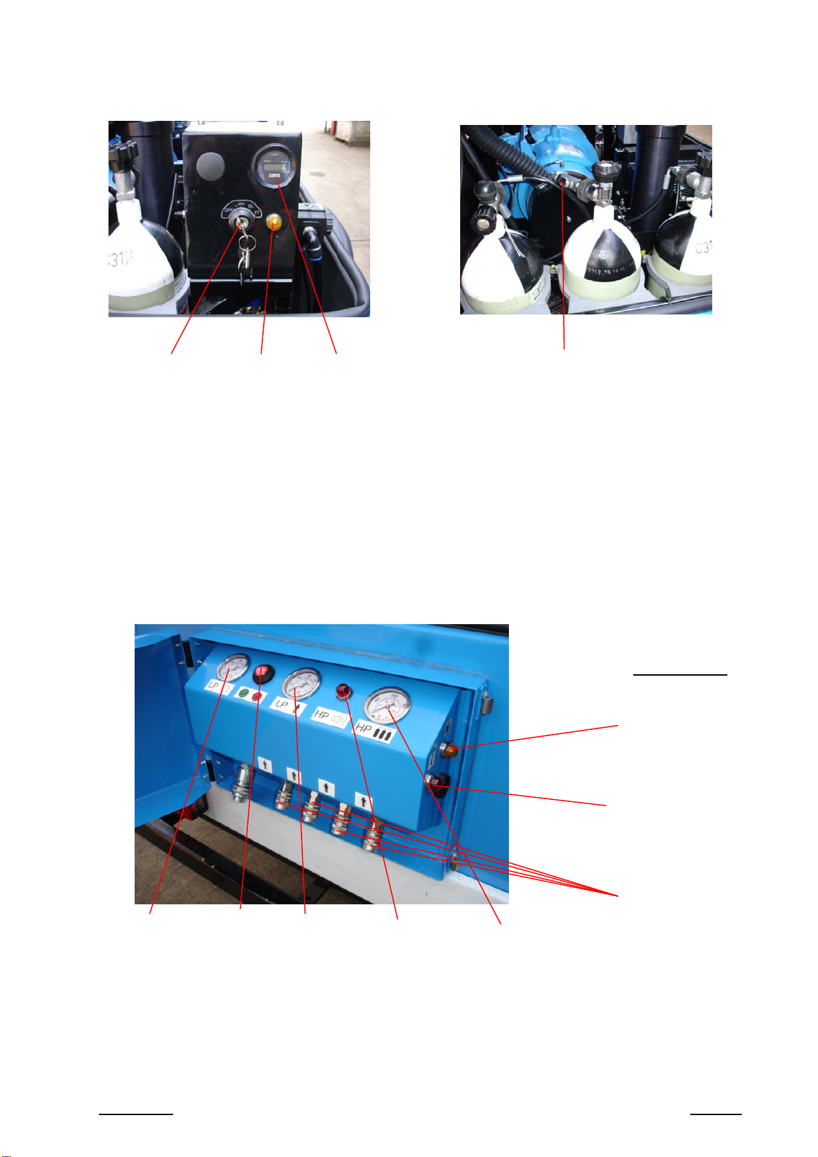
When the air reserve in the cylinders falls below a permissible level,
audible and visible alarms sound/flash at which time all breathing-air
apparatus wearers should immediately evacuate to a safe area.
The unit has a centrally-mounted lifting eye and is enclosed within a
steel canopy which allows the correct air flow and access to all
necessary parts for both running and service. The unit is also sound
attenuated to ensure that the noise level is within the European
regulations of <97LWA.
Ahinged high-level airintakeisprovided which,intheoperationalmode,
is pivoted to the vertical. Off site the intake tube is lowered to the
horizontal position. The unit should be operated on reasonably level
groundand sited topreventthere-entrainment of exhaustgasesintothe
inlet. It should also be kept well away from other polluted or toxic
atmospheres.
Simple precautions and attention to the operation and maintenance
instructionsensurethat the unitprovideshigh-qualityairandtrouble-free
operation over a long period.
IMPORTANT
A qualified attendant should be in charge of the equipment during operation and
ensure that it is operated only, and strictly, in accordance with these instructions.
The attendant should check that all hoses are laid out without kinks or tangles, are
safe from interference or damage, and orifices of all couplings are clear of dirt.
If the unit switches over to cylinder supply, the attendant should immediately
instruct the operatives to leave the hazardous area.

PAS:MAC4000 - 2 - MAR 2011
2.1 MAC4000 ON SITE

PAS:MAC4000 - 3 - MAR 2011
2.2 INSTRUMENT PANELS
Vent valve
End of Panel
Low fuel level
warning
High temperature
warning
4 x CEJN and 1 x ½”
Dyna-Quip couplings
Unregulated
supply
pressure
LP alarm
indicator Demand
mask supply
pressure HP
alarm
lamp
HP cylinder
pressure
Ignition switch Glow plug
lamp Hour meter

PAS:MAC4000 - 4 - MAR 2011
2.3 GENERAL INFORMATION
ENGINE - Kubota D722 BB-EC, 3-cylinder, water-cooled diesel engine
COMPRESSOR - Hydrovane rotary vane 037C-V05
AFTERCOOLER - Outlet temperature within 5°C of ambient
FILTRATION - Purifies air to breathing quality conforming to EN 12021
- A pressure swing dryer reduces the dewpoint to –40°C and
includes a CO and CO2suppression dryer.
CHASSIS - To full EEC regulations without brakes (braking optional)
TOWING HITCH - 50 mm ball
BATTERY - 12 volt DC – 66AH Negative earth
CAPACITY - 25 cfm (708 l/min) @ 100 psi (7 bar)
NOISE LEVEL - <97 LWA. (Better than 77dBA @ 4 metres)
STANDARD FEATURES - Chalwyn engine overspeed valve · Lifting bale · Spark arrestor
High-level air intake · Hours run meter
Fully automatic ‘fail-safe' reserve from high-pressure cylinders
with start up protection .Engine shut-down activated by either
high temperature compressor oil or low engine oil pressure
Fuel tank 28 litres with level indication
GAUGES SHOW - HP cylinder pressure · System pressure · Regulated pressure
LAMPS SHOW - Glow plug lamp and low fuel warning
AUDIBLE ALARMS - Primary air supply failure . Air reserve inadequate and low fuel
level
VISUAL INDICATOR - Shows changeover to HP reserves . Flashing beacon shows
with main audible alert and lamp shows with the low fuel alarm
OUTLETS - 4 off CEJN profile and 1 off ½" Dyna-Quip couplings
WASTES - All discharges from filter autodrains are gathered into a
container for proper disposal
QUALITY - The MAC4000 is manufactured in accordance with our Quality
Assurance Procedures approved to ISO9001/EN29001
3 CYLINDER
WATER-
COOLED
DIESEL
FUEL
CAPACITY
Litres hrs
FREE AIR
DELIVERED at
8.5 BAR/100 psi
l/min cfm
MAXIMUM
WORKING
PRESSURE
Bar psi
HP
CYLINDER
CAPACITY
Litres
DIMENSIONS (approx)
LENGTH
mm
WIDTH
mm
HEIGHT
mm WEIGHT
kgs
8 KW at
2300RPM
approx
28 8
610 21.5
10 145
Maximum
200/300 bar
3 x 9
3055 1500
1400
660

PAS:MAC4000 - 5 - MAR 2011
3.0 SAFETY PRECAUTIONS GENERAL
Run the engine in a well-ventilated area. The machine should be as
level as possible in both planes whilst in operation.
Operate unit at least 1 metre away from buildings and flammable
objects.
Do not smoke or allow flames in the refuelling area.
Avoidinhaling the exhaustfumes. Dieselengine exhaust fumescontain
a variety of toxic and asphyxiant gases. Do not run the unit except
when it is positioned down-wind from the work site.
If any fuel is spilt make sure the area is dry before starting the engine.
Many parts, especially the exhaust muffler and spark arrestor if fitted,
become very hot during operation and remain hot for a while after
stopping the engine. To avoid burns or fire hazards, always let the unit
cool before transporting, storing, or servicing.
Do not attempt any work on the compressor until the engine has been
stopped and the system completely depressurised. Wait until the
pressure gauge reads zero.
Donot insertanyobject throughthe fan guard rings. Serious damageto
the compressor and personal injury could result.
If changing the oil when the compressor is still warm, take necessary
precautions to avoid contact of hot oil with the skin. Dispose of used oil
with due regard to the environment.
Be aware of the location of the nearest fire extinguishers and their
method of operation. Great care should be taken not to spill fuel,
especially near a hot exhaust.
For safe operation prior to towing the compressor – see section 4.3.
WARNIN
G

PAS:MAC4000 - 6 - MAR 2011
4.0 OPERATING INSTRUCTIONS
Thismachine is onlyto be used by fully trained personnel in possession
of a current approved operator’s certificate.
4.1 SITING
Never run the engine in an enclosed or confined area. The unit should
be operated on reasonably level ground and sited to prevent the re-
entrainment of exhaust gases and other toxic atmospheres. The
compressorshould be positioned so thatthe drawbar points down wind,
taking account of the wind direction and the likelihood of pollution from
theworksite andother localemissions. The following points shouldalso
betaken into consideration; communications between the standby man
and the BA wearer, the route of the supply hoses.
4.2 PRE-OPERATION DAILY CHECKS
Check:-
for leaks
fuel level
engine and compressor oil levels
the unit should be level in both planes during checks and in
operation
dispose of collected condensate in a safe manner
4.3 TOWING THE COMPRESSOR
Check the towbar and coupling. Check that wheels are secure, tyres
are in good condition and inflated correctly.
Connect lighting cable to towing vehicle if applicable. Check correct
operation of all lights.
Raise the prop stand fully and lock.
Ensure breakaway cable is secured to towing vehicle (where fitted).
Release the handbrake.

PAS:MAC4000 - 7 - MAR 2011
4.4 START UP PROCEDURE
Raise canopy and carry out pre-start checks as manual.
Close canopy.
Place the wind direction indicator on the air intake.
Raise air intake to vertical position and orientate unit so that the tow bar
points downwind.
Open canopy door.
Turn ignition switch key clockwise, first position is ‘ON’ (alarm sounds),
second position is engine glow plug; for a cold engine hold in this
position until glow plug’s light goes out.
Turn key switch to 3rd (start) position. An automatic unload system will
keepthe compressor working on low pressurefor atleast 30seconds or
until the engine is warm (in cold weather this could take several
minutes).When the compressoris readythe low-pressurewarninglamp
will extinguish.
Ensure the vent valve is closed thenopen HP cylinder valves by turning
valves anticlockwise to fully open and then back half a turn – HP alarm
will sound until more than 50 bar shows on the gauge.
Check the cylinder contents gauge is above 150 bar (2,200 psi).
Close the door on the canopy.
Connect Respiratory Protective Equipment.
The breathing air unit is now ready for use.
4.5 SHUTDOWN PROCEDURE
Ensure the machine is not supporting life.
Disconnect all outlet hoses.
Run machine for 3 to 4 minutes unloaded.
Open door on canopy
Check pressures and turn off HP cylinders.
Note: If cylinder pressures are below 150 bar (2,200 psi) they must be
recharged or replaced before subsequent use.

PAS:MAC4000 - 8 - MAR 2011
Stop engine (HP alarms will sound).
Vent trapped air from HP system by opening the vent valve on the
centre cylinder.
Lower air intake and close door on canopy.

PAS:MAC4000 - 9 - MAR 2011
WARNINGS
IF A WARNING ALARM SOUNDS,
IMMEDIATELY EVACUATE ALL BREATHING
APPARATUS WEARERS TO A SAFE AREA
AN AUDIBLE AND VISUAL ALARM SHOWS:
1 Low compressor pressure
2 Malfunction of compressor or engine
3 Excessive demand
4 Restricted air intake
5 Low cylinder pressure
6 Low fuel level
7 Residual pressure from the cylinders remains after ignition is
turned off
FOR FURTHER INSTRUCTIONS AND DETAILED SERVICING METHODS
CONSULT OPERATOR’S HANDBOOK.
DO NOT ATTEMPT UNAUTHORISED REPAIRS.
REFER ANY FAULTS TO THE HIRE COMPANY.

PAS:MAC4000 - 10 - MAR 2011
5.0 WARNING SEQUENCES
5.1 Warnings are given by a combined siren and flashing beacon.
Awareness of low fuel is signalled by an audible alarm and lamp.
5.2 Ifthe primary compressorpressure drops to 8 bar, the siren soundsand
the high-pressure cylinders automatically come into operation.
If the cylinder pressure drops to about 40 bar, the siren sounds to warn
that the reserve supply is running low.
If the primary air supply is restored, the system reverts to normal mode
and cylinder supply ceases. However, if cylinder pressure has by then
droppedto 40bar, thesiren continuesto warnof low emergencysupply.
Similarly, in the event of leakage from cylinders with a pressure drop to
about40 bar, thesiren sounds eventhough primary pressureis normal.
5.3 If low engine oil pressure or high compressor oil temperature is
detected,the primary supplyis shut downand the reserve automatically
brought online.

PAS:MAC4000 - 11 - MAR 2011
6.0 MAINTENANCE
6.1 QUICK REFERENCE
MAC 4000 – Service Schedule (excluding pre-start checks)
Operation Period
Every
Day Every
50
hrs
Every
100
hrs
Every
200
hrs
Every
400
hrs
Every
500
hrs
Every
800
hrs
Annually Every
1000
hrs
Every
1500
hrs
Every
2000
hrs
Every
3000
hrs
Compressor – Hydrovane VO5
Check oil level
Clean air intake
filter
Clean oil cooler
Change air intake
filter
Change oil (Fluid
Force 2000)
Clean oil filter
Change unloader
valve seals
Change MPV
seals
Change vacuum
valve seals
Compressor drive
belt check
Engine – Kubota D722
Check oil and fuel
levels
Check fuel pipe
and clamp bands
Change engine oil initial
Clean air intake
filter
Clean fuel filter
Check fan belt
tightness
Battery electrolyte
level
Replace oil filter
cartridge
Check radiator
hoses and clamp
bands
Check air intake
line
Replace fuel filter
element
Replace fan belt
Drain sediment
from fuel tank
Replace air intake
element*
Check valve
clearances
Check fuel
injection nozzle
(pressure)

PAS:MAC4000 - 12 - MAR 2011
Operation Period
Every
Day Every
50
hrs
Every
100
hrs
Every
200
hrs
Every
400
hrs
Every
500
hrs
Every
800
hrs
Annually Every
1000
hrs
Every
1500
hrs
Every
2000
hrs
Every
3000
hrs
Check water
jacket (radiator
interior)
Check injection
pump
Check fuel
injection timer
Breathing-air Filtration
Change prefilter
element
Change duplex
filter coalescing
element
Change duplex
filter carbon
element
max
Change Hopcalite
element
Change final
stage carbon
element
Check and clean
autodrains
Pressure Swing Dryer
Service-required-lamp is illuminated automatically after 10,000 running hours.
General
Check operation of
Chalwyn valve
Check warning
alarm settings max
SERVICE PARTS
Description Qty Part NoService Interval
Pre-filter element 1 FIL0346 2000 hours/12 months
KIT0278
Duplex element – coalescing 1 FIL0347 2000 hours/12 months
Duplex element – activated carbon 1 FIL0348 1000 hours/6 months
Compressor air intake filter element 1 FIL0059 2000 hours/12 months
Engine oil filter cartridge 1 FIL0236 200 hours
Fuel filter element 1 FIL0237 200 hours
Engine air filter element 1 FIL0225 800 hours/12 months
Engine fan belt 1 BEL0041 400 hours
Hopcalite filter element 1 FIL0450 2000 hours/12 months
Carbon element 1 FIL0451 2000 hours/12 months
Compressor service kit KM71 1 KIT0229 2000 hours
Compressor separator change kit KS71 1 KIT0014 6000 hours
2000-hour mineral oil 5 litres OIL0001 2000 hours
HPO High temp synthetic oil 5 litres OIL0032 2000 hours
Drive belt 1 BEL0034 1000 hours
1 amp fuse 1 ELE0628
2 amp fuse 1 ELE0629
3 amp fuse 1 ELE0630
Wind direction indicator 1 IND0061

PAS:MAC4000 - 13 - MAR 2011
6.2.1 Compressor

PAS:MAC4000 - 14 - MAR 2011
6.2.2 Replacing compressor intake filter
a) Release the securing clips retaining the intake filter cover
b) Remove the intake filter cover
c) Remove the filter element and replace
d) Refitthe intake filter cover ensuring that the dust discharge valve points
directly downwards
Securing
clip (2 off)
Filter cover
Dust
discharge
valve
Filter
element

PAS:MAC4000 - 15 - MAR 2011
6.2.3 Checking the Oil Level
Every Day
Checking the Oil Level
1 Check the oil level when the compressor is cold (prior to start up), stopped
and at zero pressure.
2 Oil should fill the sight glass (A).
3 Top up, if necessary, using an APPROVED OIL.
Topping Up the Oil
1 Ensure the compressor is depressurised. The pressure gauge must read
zero.
2 Slowly unscrew the filler plug (B). If there is any escape of oil or air, DO
NOTCONTINUE REMOVINGTHE PLUGUNTIL ALLTHE PRESSUREIS
RELEASED.
3 Remove the filler plug (B) and bonded seal (C).
4 Top up with an APPROVED OIL to the top of the filler hole.
5 Fit bonded seal to the filler plug. Refit and tighten the filler plug.
Always observe safety precautions when working on the compressor. See page 5

PAS:MAC4000 - 16 - MAR 2011
6.3.1 Engine

PAS:MAC4000 - 17 - MAR 2011
6.3.2 Changing the Engine Oil

PAS:MAC4000 - 18 - MAR 2011
6.3.3 Fuel
Table of contents
Other Dräger Air Compressor manuals
Popular Air Compressor manuals by other brands

Husky
Husky Trim Plus H1503TP Operator's manual

Craftsman
Craftsman 919.165381 owner's manual

EINHELL
EINHELL 40.206.55 Original operating instructions

California Air Tools
California Air Tools 20020AD owner's manual

Sparmax
Sparmax AC-27 user manual

Scheppach
Scheppach HC20Si Twin Translation of original instruction manual