ZDUE-GSM-PLUS-V Installation Instructions
1
Safety Notes
General information:
The ZDUE-GSM-PLUS-V is compliant with the European
EN60950: 2006 standard, Safety of information technology
equipment. Only professionally trained electricians are
authorized to perform the installation of the ZDUE-GSM-
PLUS-V, The generally accepted technical rules and
regulations governing the setting up of telecommunications
equipment and end devices shall be observed.
The ZDUE-GSM-PLUS-V is not designed to be connected
to IT systems for electrical energy supply.
Please read through these installation instructions carefully
before using the device.
Disconnection from the power supply circuit:
An easily accessible, all-pole circuit breaker in the power
supply circuit is required for the house installation.
Alternatively, a single-pole circuit breaker can be used in
the outer conductor as long as a distinct neutral conductor
has been integrated into the supply line. In Germany, the
circuit breaker must at least meet the requirements of the
DIN VDE series 0100 standard.
Installation fuse:
For the house installation, there must be an installation
fuse that complies with the DIN VDE series 0100 standard
and is properly adapted to the cable cross-section of the
power supply line. The additional short-circuit protection
must have a selectivity of I > 1500A.
Transient Over voltages:
The ZDUE-GSM-PLUS-V are devices in Over voltage
Category III. If the ZDUE-GSM-PLUS-V are likely to be
exposed to higher transient over voltages than those in
Over voltage Category III when connected, it will be
necessary to take further safety precautions for the
installation.
Cable Routing:
The space between antenna/data lines and lines carrying
dangerous voltages must be at least 10 mm.
Mounting the antenna:
When installing an antenna outdoors, it is absolutely
necessary that the antenna is installed properly by
qualified technicians.
The outdoor antenna must be grounded to protect it
against lightning strikes. The outdoor antenna shield must
be reliably connected with the protective ground.
The corresponding national installation guidelines must be
followed for the installation process.
In Germany, this is the VDE 0185 (DIN EN 62305) Parts 1
to 4 series of standards for buildings equipped with
lightning protection systems and the VDE 0855 (DIN EN
60728-11) series of standards if there is no lightning
protection system installed.
The recommended radiation limits of the German
Commission on Radiological Protection (www.ssk.de) from
13/14 September 2001 must be observed.
Uses:
The ZDUE-GSM-PLUS-V is a device designed for the
remote inquiry and the remote monitoring of electricity,
heat, gas and water meters. It is design to be used in GSM
networks.
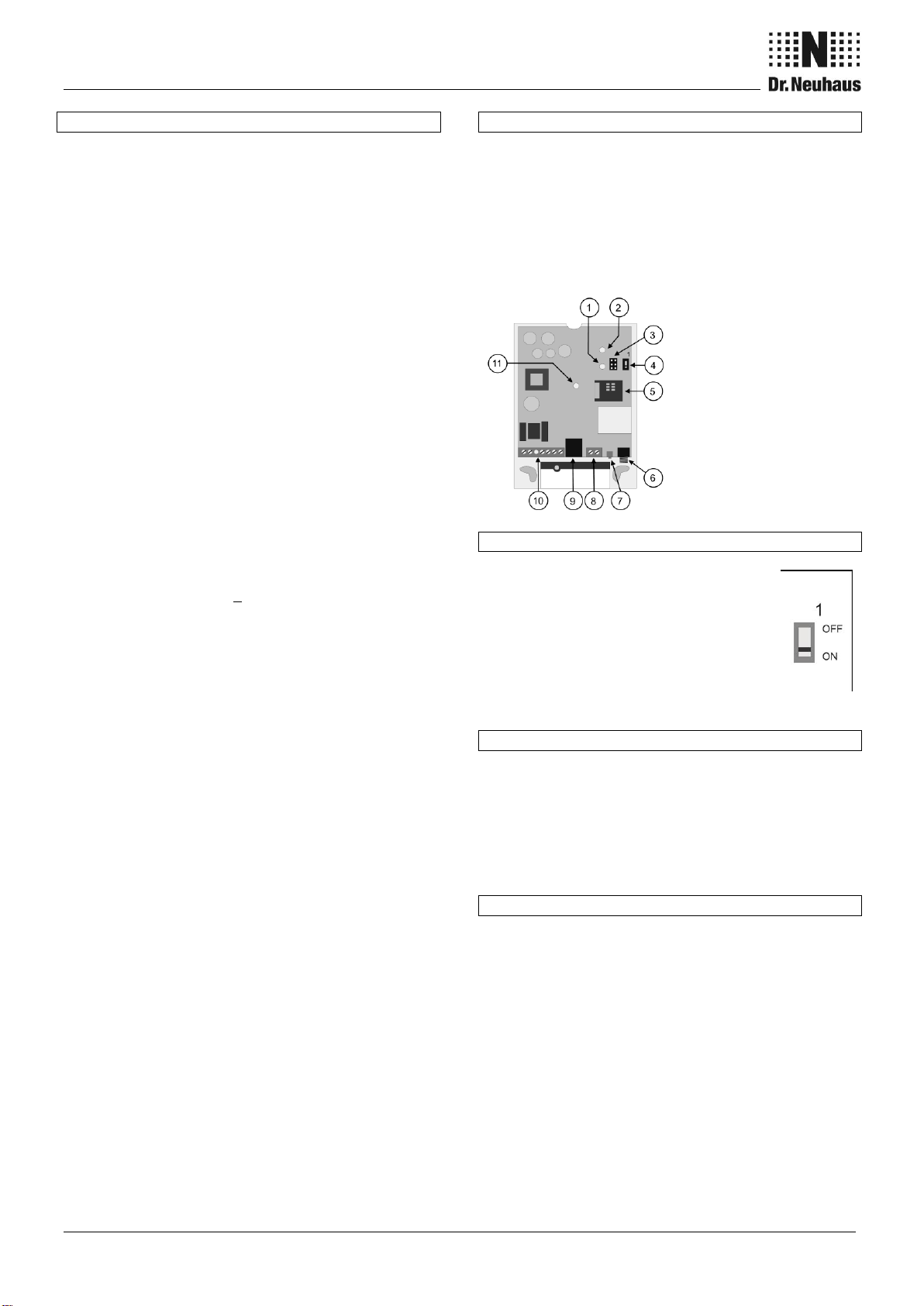
Opening the device
In order to insert the SIM card or to access the DIP switch,
you first have to open the device:
1. First disconnect all the poles of the device from the
electricity supply if it is plugged in there.
2. Now unscrew the screw in the terminal cover and
remove the cover.
3. Now remove the device lid.
Service connector
(optional)
Altering the device settings
Using the DIP switch (4) you toggle between
the both operating modes, meter mode and
AT command mode.
In meter mode (OFF), the device can be
adjusted locally via one of the meter
interfaces or remotely via communication
commands according to EN 62056-21. In this
case, the device will then operate using the
parameters that have been set.
Setting the PIN of the SIM card
In order to operate the ZDUE-GSM-PLUS-V, you will
require a 3V plug-in SIM card from a GSM network
operator.
A ZDUE-GSM-PLUS-V having factory default settings
expects a SIM card with a PIN 0000. The PIN setting of the
ZDUE-GSM-PLUS-V can be changed in the device
settings.
Inserting the SIM card
Insert the SIM card as follows:
1. Open the SIM card holder by gently pressing the lid
towards the edge of the device, flip it up and insert the
SIM card into the slot in the holder. The gold-plated
contacts on the SIM card have to lie on the gold-plated
contacts of the holder when the holder is closed.
Close the lid of the SIM card holder and lock it by
pressing it gently back towards the center of the
device. You will feel it click into place.
2. Now replace the device lid and the terminal cover.