DR Premier Quick start guide

CONTACT US AT www.DRpower.com 1
Serial No.
Order No.
DR Power Equipment
Toll-free phone: 1-800-DR-OWNER (376-9637)
Website: www.DRpower.com
Read and understand this manual and all instructions before operating the DR LEAF and LAWN VACUUM.
DR®LEAF & LAWN VACUUM
SAFETY & OPERATING INSTRUCTIONS
Models:
Premier
Pro
Pro-XL

2DR® LEAF and LAWN VACUUM
This indicates a hazardous situation, which, if not avoided, could result in death or serious injury.
Table of Contents
Chapter 1: General Safety Rules............................................................................................................................................................ 3
Chapter 2: Setting Up the DR LEAF and LAWN VACUUM .................................................................................................................. 8
Chapter 3: Operating the DR LEAF AND LAWN VACUUM................................................................................................................. 30
Chapter 4: Maintaining the DR LEAF and LAWN VACUUM ............................................................................................................... 38
Chapter 5: Troubleshooting .................................................................................................................................................................. 42
Chapter 6: Parts Lists and Schematic Diagrams.................................................................................................................................. 44
Conventions used in this manual
Serial Number and Order Number
A Serial Number is used to identify your machine and is located on the Serial
Number Label on your machine. An Order Number is used to check and
maintain your order history and is located on the upper left portion of your
packing slip. For your convenience and ready reference, enter the Serial
Number and Order Number in the space provided on the front cover of this
manual.
Additional Information and Potential Changes
DR Power Equipment reserves the right to discontinue, change, and improve its
products at any time without notice or obligation to the purchaser. The
descriptions and specifications contained in this manual were in effect at
printing. Equipment described within this manual may be optional. Some
illustrations may not be applicable to your machine.
California Proposition 65
This information is important in the proper use of your machine. Failure to follow this instruction could result in damage to
your machine or property.
This indicates a hazardous situation, which, if not avoided, could result in minor or moderate injury.

CONTACT US AT www.DRpower.com 3
Read this safety & operating Instructions manual before you use the DR LEAF and LAWN VACUUM. Become familiar with the
operation and service recommendations to ensure the best performance from your machine. If you have any questions or need
assistance, please contact us at www.DRpower.com or call toll-free 1-800-DR-OWNER (376-9637) and one of our Technical
Support Representatives will be happy to help you.
Chapter 1: General Safety Rules
Labels
Your DR LEAF and LAWN VACUUM carries prominent labels as reminders for its proper and safe use. Shown below are copies of
all the Safety and Information labels that appear on the equipment. Take a moment to study them and make a note of their
location on your machine as you set up and before you operate the unit. Replace damaged or missing safety and information
labels immediately.
#153421
#137581
#342781
#372301
#372291
#188871
#342791

4DR® LEAF and LAWN VACUUM
Protecting Yourself and Those around You
Safety for Children and Pets
Tragic accidents can occur if the operator is not alert to the presence of children and pets. Children and pets are often attracted to
the machine and the vacuuming activity.
Never
assume that children or pets will remain where you last saw them. Always follow
these precautions:
•Keep children and pets at least 100 feet from the working area and ensure they are under the watchful care of a responsible
adult.
•Be alert and always turn off the lawn tractor engine and the DR Leaf and Lawn Vacuum engine if children or pets enter the
work area.
•Before and while moving backwards, look behind, and
down
for small children and pets. You cannot see directly behind the
collector box.
•Never allow children to operate the Lawn Tractor or Vacuum.
•Never allow children or pets to play in the collector. If they become trapped in the enclosure they may be exposed to
temperatures similar to leaving a child or pet in a car with the windows closed on a sunny day.
•Use extra care when approaching blind corners, shrubs, trees, or other objects that may obscure your vision.
This is a high-powered machine, with moving parts operating with high energy at high speeds. You must use proper clothing and
safety gear when operating this machine to prevent or minimize the risk of severe injury. This machine can cut, and sever parts of
your body if they become in contact with the moving impeller blades. Always take the following precautions when operating this
machine:
•Always wear protective goggles or safety glasses with side shields while operating either your tractor lawn deck, the vacuum
system, or when performing an adjustment on your DR Leaf and Lawn Vacuum to protect your eyes from possible foreign
objects thrown from the machine.
•Avoid wearing loose clothing or jewelry, which can catch on the machine’s moving parts.
•We recommend wearing gloves while using the DR Leaf and Lawn Vacuum. Be sure your gloves fit properly and do not have
loose cuffs or drawstrings.
•Wear shoes with non-slip treads when using your DR Leaf and Lawn Vacuum. If you have safety shoes, we recommend
wearing them. Do not use the machine while barefoot or wearing open sandals.
•Wear long pants while operating the DR Leaf and Lawn Vacuum.
•Use ear protectors or earplugs rated for at least 20 dba to protect your hearing.
#388491
#388501

CONTACT US AT www.DRpower.com 5
Safety with Gasoline - Powered Machines
Gasoline is a highly flammable liquid. Gasoline also gives off flammable vapor that can be easily ignited and cause a fire or
explosion. Never overlook the hazards of gasoline. Always follow these precautions:
•Never run the engine in an enclosed area or without proper ventilation as the exhaust from the engine contains carbon
monoxide, which is an odorless, tasteless, and deadly poisonous gas.
•Store all fuel and oil in containers specifically designed and approved for this purpose and keep away from heat and open
flame, and out of the reach of children.
•Replace rubber fuel lines and grommets when worn or damaged and after 5 years of use.
•Fill the gasoline tank outdoors with the engine off and allow the engine to cool completely. Don't handle gasoline if you or
anyone nearby is smoking, or if you're near anything that could cause it to ignite or explode. Reinstall the fuel tank Cap and
fuel container cap securely.
•If you spill gasoline, do not attempt to start the engine. Move the machine away from the area of the spill and avoid creating
any source of ignition until the gas vapors have dissipated. Wipe up any spilled fuel to prevent a fire hazard and properly
dispose of the waste.
•Allow the engine to cool completely and empty the collector box before storing the DR Leaf and Lawn Vacuum in any
enclosure. Remember, decomposing material can generate heat and start a fire. Never store the machine with gas in the
tank or a fuel container, near an open flame or spark such as a water heater, space heater, clothes dryer or furnace.
•Never make adjustments or repairs with the engine running. Shut down the engine, disconnect the spark plug wire, keeping it
away from the spark plug to prevent accidental starting, wait 5 minutes before making adjustments or repairs.
•Never tamper with the engine’s governor setting. The governor controls the maximum safe operation speed and protects the
engine. Over-speeding the engine is dangerous and will cause damage to the engine and to the other moving parts of the
machine. If required, see your authorized dealer for engine governor adjustments.
•Keep your hands and combustible substances away from the engine when it is hot and clean the engine area after each use.
•To reduce fire hazard, keep the engine cooling fins and muffler area free of debris build-up such as leaves, grass, oil, grease or
any other combustible material.
•Never cover the machine while the muffler is still hot.
•Do not operate the engine with the air cleaner or the carburetor air intake cover removed, except for adjustment. Removal of
such parts could create a fire hazard.
•Do not use flammable solutions to clean the air filter.
•The muffler and engine become very hot and can cause a severe burn; do not touch.
•The exhaust area on the engine becomes very hot with use. Allow the engine to cool before doing maintenance or making
adjustments.

6DR® LEAF and LAWN VACUUM
Slope Operation
General Safety
Slopes are a major factor related to tip over accidents, which can result in severe injury. All slopes require caution. If you feel
uneasy on a slope, do not vacuum it. Always take the following precautions when using this machine on slopes:
ALWAYS:
•Vacuum up and down the face of slopes, never across. Exercise extreme caution when changing direction on slopes.
•Remove objects such as stones, glass and metal objects such as cans.
•Watch out for holes, ruts, or bumps. Tall grass can hide obstacles.
NEVER:
•Never vacuum near drop-offs, ditches, or embankments. Your tractor and the vacuum may tip over.
•Never vacuum on slopes greater than 15 degrees or any excessively steep slopes.
•Never vacuum on wet slopes. Reduced traction could result in slipping and a possible roll over.
This is a high-powered machine, with moving parts operating with high energy at high speeds. You must operate the machine
safely. Unsafe operation can create a number of hazards for you, as well as anyone else in the nearby area. Always take the
following precautions when using this machine:
•Never allow people who are unfamiliar with these instructions to use the DR Leaf and Lawn Vacuum.
•To be safe, do not operate the machine near small children or pets, and never allow children to operate the vacuum. Stop the
vacuum engine and tractor engine when another person or pet approaches.
•Never allow people or pets to ride in the collector box or on the frame.
•Never run the engine unless the chute, fabric collector sleeve, and hose are all securely in place and the engine frame is
securely connected to the cart frame.
•Check behind your DR Leaf and Lawn Vacuum before backing up. You cannot see directly behind the collector box.
•Never attempt to open or empty the collector while the lawn tractor deck is engaged or the DR Leaf and Lawn Vacuum engine
is running. Debris may exit at high velocity as you begin to open the collector.
•Do not operate in sandy areas where you will vacuum large quantities of sand. Sand will erode the vacuum housing. Check
for holes after each use and replace the housing and liner when holes develop.
•Never operate the machine on slopes greater than 15 degrees.
•Never tow the DR Leaf and Lawn Vacuum faster than 8 mph.
•Always shut off the lawn tractor engine and the DR Leaf and Lawn Vacuum engine and disconnect the spark plug wire before
attempting to clear any obstructions from the hose.
•Use the DR Leaf and Lawn Vacuum only in daylight.
•Never straddle or reach over the engine area at any time.
•Use only your hands to operate the DR Leaf and Lawn Vacuum engine controls.
•Do not, under any conditions, remove, bend, cut, fit, weld, or otherwise alter standard parts on the DR Leaf and Lawn
Vacuum. Modifications to your machine could cause personal injuries and will void your warranty.
•Do not alter or tamper with safety devices or shields. Make sure they are in their proper position.
•While using the DR Leaf and Lawn Vacuum, do not hurry or take things for granted.
•Never leave the DR Leaf and Lawn Vacuum unattended with its engine running.
•Do not operate the machine when under the influence of alcohol, drugs, or medication.

CONTACT US AT www.DRpower.com 7
A Note to All Users
Under California law, and the laws of some other states, you are not permitted to operate an internal combustion engine using
hydrocarbon fuels without an engine spark arrester. This also applies to operation on US Forest Lands. All DR®LEAF and LAWN
VACUUMS shipped to California, New Mexico and Washington State are provided with spark arresters. Failure of the owner or
operator to maintain this equipment in compliance with state regulations is a misdemeanor under California law and may be in
violation of other state and/or federal regulations. Contact your State Park Association or the appropriate state organization for
specific information in your area.
No list of warnings and cautions can be all-inclusive. If situations occur that are not covered by this manual, the operator must
apply common sense and operate this DR®LEAF and LAWN VACUUM in a safe manner. Contact us at www.DRpower.com or
call 1-800-DR-OWNER (376-9637) for assistance.
The DR Leaf and Lawn Vacuum must be operated safely to prevent or minimize the risk of minor or moderate injury. Unsafe
operation can create a number of hazards for you. Always take the following precautions when operating this machine:
•Keep in mind that the operator or user is responsible for accidents or hazards occurring to other people, their property, and
themselves.
•Never use the DR Leaf and Lawn Vacuum to vacuum anything but yard waste, such as leaves, grass, small twigs and pine
cones.
•If the machine starts to make an unusual noise or vibration, immediately shut off the engine, disconnect the spark plug wire,
and allow all moving parts to come to a complete stop and cool. Inspect for clogging or damage. Clean and repair and/or
replace damaged parts.
•See manufacturer’s instructions for proper operation and installation of accessories. Only use accessories approved by DR
Power Equipment.
•Always keep the equipment in a good safe operating condition. Always make certain nuts and bolts are tight and always use
the supplied self-locking hardware; do not substitute.
•For best performance we recommended that you operate your Leaf and Lawn Vacuum in temperatures 40°F and above.

8DR® LEAF and LAWN VACUUM
Chapter 2: Setting Up the DR LEAF and LAWN VACUUM
It may be helpful to familiarize yourself with the controls and features of your DR LEAF and LAWN VACUUM as shown in Figure 1
before beginning these procedures. If you have any questions at all, please feel free to contact us at www.DRpower.com.
DR LEAF and LAWN VACUUM Controls and Features
Collector Sleeve
Hose Support
Dump
Lever
Collector
Outlet
Chute
Cart Bed
Power Unit
Wheels
Figure 1
Pneumatic
Tires
Tow Hitch
Dump
Handle
Jack
Battery (Electric
Start Models)
(Manual start)
On/Off
Switch
Choke
Air Filter
Gas Shut-Off
Starter Recoil Handle
Key
Switch
Gas Fill
Inlet Hose Assembly
Cable
(Electric start)
Muffler
Throttle
Choke
Air Filter
Gas Shut-Off
Starter Recoil Handle
Gas Fill
Muffler
Throttle
Foot Assist
(Pro Models Only)

CONTACT US AT www.DRpower.com 9
Specifications
PREMIER
PRO
PRO-XL
Engine
DR Power Equipment R225
DR Power Equipment R300
DR Power Equipment R390
Ft-lbs Torque
9.59
13.28
16.96
Starting
Manual or Electric w/ Recoil Backup
RPM
3800
3800
3800
Impeller
Steel, 5 Blades w/Serrated Teeth
Teel, 5 Blades w/Serrated Teeth
Weight
13.2 Lbs
13.2 Lbs
13.2 Lbs
Mount
Keyless Tapered Direct Engine Mount
Vacuum
2038 CFM
2038 CFM
2038 CFM
Suction
66 MPH
66 MPH
66 MPH
Hose
8" ID
8" ID
8" ID
Collector
Clamshell Design
Clamshell Design
Clamshell Design
Volume
32 Cubic Feet, 240 Gallons
44 Cubic Feet, 330 Gallons
Capacity
500 Lbs
800 Lbs
800 Lbs
Fabric Enclosure
1800 Denier Polyester with Bonded
PVC Backing
1800 Denier Polyester with Bonded
PVC Backing
1800 Denier Polyester with Bonded
PVC Backing
Dump Tilt
60°
60°
60°
Cart
Detachable, High Strength PE Cart Bed
Frame
Welded Steel, 2 Piece Modular Design
Impeller Housing
Steel Scroll (.12”), Sideplate (.12”)
Wheels
Pneumatic 5.30/4.50-8 4 Ply w/ Tube
Quantity
2 (1 Per Side)
4 (2 Per Side)
4 (2 Per Side)
Tire Size
14" Diameter x 4.5" Wide
Jack
Optional Accessory
Heavy Duty w/ 4" Wheel (Ships
installed)
Heavy Duty w/ 4" Wheel (Ships
installed)
Lawn Mower
12 HP Min Flat Terrain otherwise 14 HP
17 HP Min
17 HP Min
Lawn Mower Hitch
Pin Hitch 8" to 15" from the Ground
Battery (E/S Models)
9Ah, Spade Terminals
Dimensions
87.8" L x 40.1" W x 61" H
87.8" L x 49.5" W x 61" H
Weight
342 Lbs M/S, 355 Lbs E/S
411 Lbs M/S, 423 Lbs E/S
425 Lbs M/S, 437 Lbs E/S
Parts supplied in packaging:
•Power Unit
•Cart Bed with Frame
•Axle
•Tube Frame Handle
•Product Package
oSafety and Operating Instructions Manual
oEngine Manual
oHardware (see figure 3)
•Large Parts Box (see Figure 4)
•Parts in Cart Bed (Figure 2):
o2 Wheels (Premier)
o4 Wheels (Pro and Pro XL)
oInlet Hose Assembly (with Coupling and Clamps)
oOutlet Duct
oFlexible Oil Fill Funnel
Figure 2
Wheels
Inlet Hose
Assembly
Outlet Chute

10 DR® LEAF and LAWN VACUUM
Assembly Parts Identification
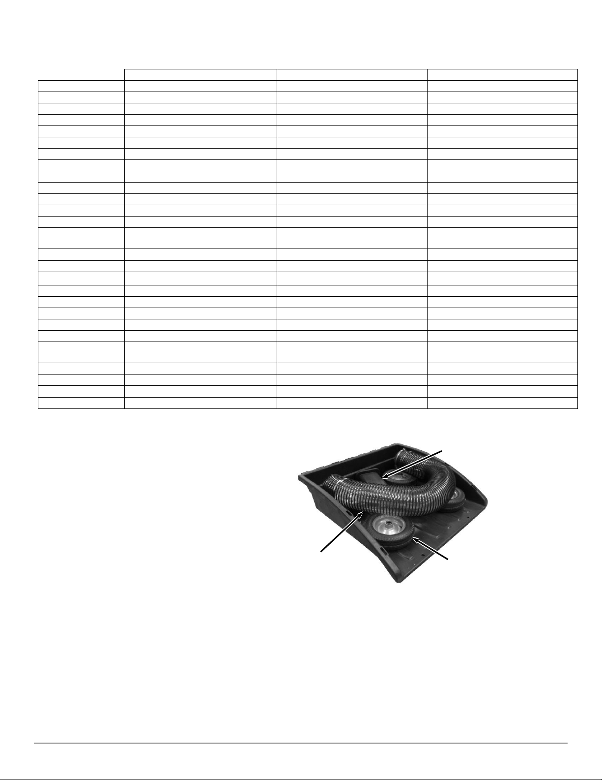
Compare the contents of the Parts Boxes and Hardware Packages with the Parts Supplied lists and Figures 3 thru 8 below. If there
are any questions contact us at www.DRpower.com or call 1-800-DR-OWNER (376-9637).
There may be hardware left over when assembly is finished. This is sometimes expected in the process of filling hardware bags at
the factory.
Product Package Hardware (Figure 3):
Item # Part # Description Qty
1 .............A0000253563....... Pin, Clevis, 1/2" X 4.5", ZP ....................... 1
2 .............211541 ................. Pin, Clevis, 1/2" X 3.5", ZP ....................... 2
3 .............350371 ................. Bolt, Hex, 7/16-20, Impeller Tool ............. 1
4 .............350291 ................. Knob Set, 5/16-18 W/Lock, 17 Pack ......... 1
5 .............350271 ................. Bolt, C-Head, 5/16-18 X 1.75″, ZP ............ 2
6 .............112411 ................. Washer-Flat 5/16 USS............................... 2
7 .............110761 ................. Nut-Lock Nylon 5/16-18 ........................... 2
8 .............337871 ................. Pin, Cotter, Hair, 1/4-3/8.......................... 4
9 .............160031 ................. Pin, Hitch Clip 1/2"................................... 3
10 ...........189671 ................. Washer, Flat, 1/2", Rubber ....................... 1
11 ...........350331 ................. Bolt, C-Head, 5/16-18 X 1.75”, ZP............ 2
12 ...........106681 ................. Nut, Flange 5/16-18.................................. 2
*11, 12 only included in PRO/ PRO XL models*
Large Parts Box Contents (Figure 4):
Item # Description Qty
1 .............Tube Frame Assembly, LH……………………………….................. 1
2 .............Tube Frame Assembly, RH……………………………….................. 1
3 .............Small Parts Box……………………………………………….................. 1
4 .............Enclosure, Fabric ………………………………. ............................... 1
5 .............Rod, Support, Hose…………………………………………................. 1
6 .............Hinge, Split, Frame Collector, RH……………………… ............... 1
7 .............Hinge, Split, Frame Collector, LH……………...………................ 1
8* ...........Bracket, Foot Assist……………………………...…………................. 1
9 .............Gas Spring, 500-300 mm, 150 lb………………………... .............. 2
10 ...........Batten, FRP…………………….…………...……. ............................... 1
11 ...........Pin, Hinge……………….……….……….……… ................................ 1
12 ...........Handle, Tube Frame ………………….………................................ 1
13 ...........Hinge Tube Assembly…………….…………. ................................ 1
14 ...........Outer Link Assembly, Bottom Rear ……... .............................. 1
15 ...........Inner Link Assembly, Top Rear ……………………………………... . 1
16 ...........Retainer, Enclosure LH…………………………………….................. 1
17 ...........Retainer, Enclosure RH……………………………………... .............. 1
*8, only included in PRO/PRO XL models*
1
Figure 3
2
4
5
6
3
10
7
9
8
11
12
Figure 4
12
10
14
3
4
5
1
6
2
7
8
9
11
15
13
16
17

CONTACT US AT www.DRpower.com 11
Small Box Parts (Figure 5):
Item # Part # Description Qty
1 .............A0001844373..... Bracket, Stop............................................... 2
2 .............354421 ............... Strap and Hook Set .................................... 1
3 .............338021 ............... Bracket, Axle................................................ 2
4 .............350211 ............... Hardware Set, Wheels ................................ 1
5 .............A0002281395..... Hardware Set, Enclosure ............................ 1
6 .............388671 ............... Hardware Set, Power Unit.......................... 1
7 .............337911 ............... Retainer, Enclosure, Front.......................... 2
Master Tool List:
Item # Description Qty
1 .............Ratchet............... ..................................................................... 1
2 .............5/16" Wrench .... ..................................................................... 1
3 .............7/16" Wrench .... ..................................................................... 1
4 .............7/16" Socket ...... ..................................................................... 1
5 .............1/2" Wrench ...... ..................................................................... 1
6 .............1/2" Deep Socket .................................................................... 1
7 .............9/16" Wrench .... ..................................................................... 1
8 .............9/16" Deep Socket .................................................................. 1
9 .............3/4" Wrench ...... ..................................................................... 1
10 ...........3/4" Socket ........ ..................................................................... 1
11 ...........13mm Wrench or Adjustable Wrench .................................... 1
12 ...........Scissors or diagonal cutters.................................................... 1
13 ...........Pliers .................. ..................................................................... 1
14 ...........Wire Cutters....... ..................................................................... 1
15 ...........Hammer ............ ..................................................................... 1
16 ...........Utility Knife ........ ..................................................................... 1
17 ...........Flat head Screwdriver or 7mm Wrench .................................. 1
18 ...........Tire Pressure Gauge................................................................ 1
19 ...........Air pump or compressor......................................................... 1
20 ...........Safety Glasses…....................................................................... 1
21 ...........Floor Jack……..….. .................................................................... 1
Figure 5
1
3
4
2
5
7
6

12 DR® LEAF and LAWN VACUUM
1
2
4
3
Figure 6
5
Power Unit Hardware (Figure 6):
Item # Part # Description Qty
1 ............. 265561 ............ Bolt, HCS, 1/2-13 X 2.75", GR5, ZP............... 2
2 ............. 350231 ............ Bolt, Hex, Flange, 5/16-18 X .75" .................. 4
3 ............. 112431 ............ Washer, Lock, 5/16", Split, ZP....................... 4
4 ............. 112411 ............ Washer, Flat, 5/16" USS, ZP.......................... 4
5 ............. 333351 ............ Nut, Nylon Lock, Flange, 1/2-13.................... 2
Enclosure Hardware (Figure 7):
Item # Part # Description Qty
1……………123371……….Bolt-Hcs 3/8-16 X 2 3/4 Gr5 Zp .........………….3
2……………150451……….Bolt-Hcs 5/16-18 X 1-3/4 Gr5 Zp.......………….4
3……………101471……….Bolt-Hcs 5/16-18x2 1/4 Gr2 Zp.......... ………….4
4……………112411……….Washer-Flat 5/16 Uss ........................………….4
5……………110731……….Nut, Nylon Lock, 1/4-20, ZP..............………..10
6……………110761……….Nut-Lock Nylon 5/16-18 ....................………….4
7……………164131……….Nut-Lock Nylon 3/8-16 Lowpro.........………….3
Wheel Hardware (Figure 8):*
Item # Part # Description Qty
1 ............. A0001216052....Washer, 1.00"ID X 1.58"OD X .134" Thick.. 4**
2 ............. 123341 ..............Bolt, HCS, 3/8-16 X 1.75", GR5, ZP............. 4
3 ............. 333331 ..............Nut, Nylon Lock, Flange, 3/8-16.................. 4
4 ............. 126851 ..............Pin, Cotter, 3/16" X 1.5"............................... 2
**Only two needed for Premier (single wheel) machines.
Installing the Wheels
(Use Wheel Hardware Bag Set, see Figure 8)
Tools Needed:
•9/16" Wrench and 9/16”Ratcheting Socket
•Pliers
1. Tip the Cart over to access the Frame (Figure 9).
2. Position the Axle Brackets and loosely secure with four 3/8-16 X 1.75"
Bolts and Locknuts using a 9/16" Wrench and Ratcheting Socket.
3. Slide the Axle through the Brackets until the same amount sticks out on
the side. Do not tighten the hardware until you are finished step 7 on the
following page.
1
Figure 8
2
3
4
Axle Brackets
Figure 9
Frame
Axle
Hardware
1
Figure 7
3
5
6
2
4
7

CONTACT US AT www.DRpower.com 13
4. For Machines with Dual Wheels only: Slide a Wheel onto the Axle with the
Valve Stem facing in and install a Washer against the Wheel (Figure 10).
Note: No Washers are needed against the Axle Brackets. Dual Wheel machines use
one washer between the Dual Wheels and one on the outside. Single Wheel
machines only use one Washer on the outside.
5. For all Machines: Install a Wheel (second wheel for Dual Wheel models)
with the Valve Stem facing out and place a Washer against the Wheel
(Figure 11).
6. Secure the Wheel/s onto the Axle with a Cotter Pin. Use Pliers to bend the
ends of the Cotter Pin to secure the Wheels.
7. Repeat for the Wheel/s on the opposite side.
8. Tighten axle bracket hardware.
9. Tip the Cart over onto the Wheels.
Installing the First Gas Spring
1. Tilt the Cart Bed up by pulling the Lift Handle out and lifting up on the
front of the Cart (Figure 12).
Note: In the next step, the Gas Spring needs to be installed with the larger end
attached to the Frame and the thin Shaft end to the Cart Bed.
2. Insert the right side Gas Spring onto the Studs by pressing the holes in
the ends of the Gas Spring over the Studs. They will snap into place.
(Figure 13).
3. Before installing the second gas spring, the foot assist will need to be
installed (Figure 4, item 8) *(PRO MODELS ONLY). Leave the Cart in the
up position for the following procedure. (PREMIER models skip to step 7)
4. Remove the two 5/16-18 nuts using a 1/2" wrench while keeping a finger
on the head of the carriage bolt inside the bed so it does not rotate.
5. Drop two Carriage bolts, 5/16-18 X 1.75″, Item 11 found in the product
pack (Figure 3) into the open square holes directly to the right of the area
where the nuts were just removed.
6. Fit the foot assist up to the carriage bolts as shown in Figure 15 and
secure using a 1/2" wrench and the two 5/16-18 flange nuts previously
removed, and two additional 5/16-18 flange nuts, item 12 found in the
product pack (Figure 3). Make sure to keep a finger on the head of the
carriage bolts inside the bed when tightening.
7. The 2nd gas spring will be installed once the collector is completely
assembled, page 24.
Dump Lever
Figure 12
1
2
2nd Dual Wheel
or single Wheel
(Valve Stem and
Grease Fitting
facing out)
Figure 11
Washer
Cotter Pin
Axle
1st Dual Wheel (Valve Stem and
Grease Fitting facing in)
Figure 10
Large Washer
Gas
Spring
Figure 13
Stud
Stud
4 Carriage Bolts and Flange Nuts
Figure 15
Figure 14
5/16-18 Nuts
Nuts

14 DR® LEAF and LAWN VACUUM
Assembling the Power Unit
(Use Power Unit Hardware Package, see Figure 6)
Tools Needed:
•1/2" Wrench or 1/2" Ratcheting Socket
•3/4" Wrench and 3/4" Ratcheting Socket
•Scissors / diagonal cutters
•Optional Floor Jack
1. Cut the cable tie holding the machine keys and place them in a safe
location not to be lost.
2. Place the Outlet Chute on top of the Impeller Housing (make sure to
orient as shown) and secure with four Bolts, Lock Washers, and Flat
Washers using a 1/2" Wrench or socket (Figure
16)
.
Installing the Power Unit
(Use Power Unit Hardware Package, see Figure 6)
1. Position the Power Unit at the front of the Cart with the Tow Hitch
facing forward and the rear holes aligned.
2. Lift the Cart Frame to align the rear hole in the Engine Unit with the hole
in the Frame and insert a 1/2" X 3.5" Clevis Pin and Hitch Clip (Clevis
Pins and Hitch Clips are provided in the Product Package (Figure 18).
3. Chock the Wheels of the Cart to keep it from moving and have a helper
pull forward on the Outlet Chute so the Power Unit and Cart Frame front
holes are aligned (Figure 19).
Note: If you have a Floor Jack or similar you could jack under the Dump Lever to
align the Frames without a helper.
4. Insert the 2nd 1/2" X 3.5" Clevis Pin and Hitch Clip into the front holes of
the Engine Unit and Cart Frame (Figure 20).
5. Place the two 1/2-13 X 2.75" Bolts from underneath up through the two
vertical Holes and secure with 1/2-13 Locknuts using a 3/4" Wrench and
3/4”Ratcheting Socket. Remove the Floor Jack if one was used.
Clevis Pin and
Hitch Clip (From
Product Package)
Figure 18
Trailer
Frame
Jack
(Standard Equipment
on Pro and Pro XL)
Figure 17
Cart Frame
Rear
Holes
Tow
Hitch
Figure 20
2nd Clevis
Pin and
Hitch Clip
Bolts (Heads
on Bottom)
and Locknuts
We recommend having a helper to attach the Frames together. There is a
chance for injury if you attempt it alone because the Power Unit is heavy.
Outlet Chute
Figure 16
Impeller
Housing
Bolts, Lock Washers,
and Flat Washers
Chute
Chock Wheel
Figure 19
Pull Back

CONTACT US AT www.DRpower.com 15
Washer
Nut
Carriage
Bolt
Inner Link
Figure 23
Assembling the Collector
(Use Enclosure Hardware Set, see Figure 7 and Product Package
Hardware, see Figure 3)
Note: The Enclosure Fabric is intentionally a tight fit. Assembly is
much easier when you perform the following procedures in order.
Tools Needed:
•7/16" Deep Socket with Ratchet
•7/16" Wrench
•1/2”Deep Socket with Ratchet
•1/2" Wrenches
•9/16”Deep Socket with Ratchet
•9/16”Wrench
•Hammer
Installing the Inner Link Assembly
1. Remove any bubble wrap packaging from each Tube Frame and stand up both the LH and RH Tube Frames against a wall,
making note of the Pin Orientation shown (Figure 21).
2. Orient the Inner Link Assembly onto the Tube Frames with the jogged bent link as shown (Figure 22).
3. Secure the links with hardware found in the Product Package (Figure 3) by inserting two carriage bolts (Bolt, C-Head, 5/16-
18 X 1.75) through the tube, followed by two washers (Washer-Flat 5/16 USS), the scissor links and then two lock nuts (Nut-
Lock Nylon 5/16-18) as shown in (Figure 23).
4. Tighten the lock nuts using a 1/2" Wrench just enough to engage the nylon end on the nuts. Making sure the carriage bolt is
seating correctly in the square tube hole. Do not over tighten, as the scissor links need to be able to rotate freely once
secured.
LH Tube
Frame
Figure 21
RH Tube
Frame
Pin
Orientation
Tube Frames
Inner Link
Assembly
Jogged Bend
Figure 22

16 DR® LEAF and LAWN VACUUM
Installing the Side Retainers
1. Lay out the Enclosure onto a clean flat surface so the inside (black) is
facing up (Figure 27). Take note of the Sleeve location at the front of
the Enclosure.
2. Fold the side flaps so you can see the 5 holes in each of the side
pockets. Take note of the front pocket. It also has holes, but they are
facing down and are not visible (Figure 27).
3. Set the Tube Frame Assembly into the Enclosure with the Inner Link
positioned toward the Rear Flap (opposite the Front Sleeve) (Figure
28).
Note: The Left Hand and Right Hand Side Retainers are very similar and their
orientation needs to be checked prior to inserting into the canvas
enclosure.
4. Check that the left hand and right hand side retainers are oriented correctly by holding up one retainer at a time. With the
retainer on the outside, feed the studs through the Tube Frame Slots. The parts will be oriented correctly if all 5 studs feed
through the Slots without issue. Once you have confirmed both retainers are in the correct orientation, lay them down
(keeping its same orientation) next to the Enclosure Pocket with the studs pointing up (Figure 28).
5. Insert the front end of the Side Retainer into the rear end of the pocket so when installed the Side Retainer will be in the
same orientation shown in the photo. It works best to keep the studs tilted sideways until they all align with the Enclosure
holes, then twist the Retainer so the studs go into the holes (Figure 29).
6. Repeat steps 4 and 5 for the other Side Retainer.
Hole
Figure 29
Rear
Flap
Retainer
Stud
Stud
Hole
Front
Sleeve
Rear Flap
Inner Enclosure (Black)
Side Flaps Folded In
5 Holes on each Side
Figure 27
Figure 28
RH - Side Retainer
RH Tube
Frame
Inner Link
Rear Flap
LH Tube Frame
LH - Side Retainer
Front
Sleeve
Tube Frame Slots
Studs facing up

CONTACT US AT www.DRpower.com 17
Attaching the Enclosure,
(Use Hardware Enclosure set, see Figure 7)
It is best to do this install up against a wall, to keep the enclosure upright while
working.
1. Lift one side of the Enclosure so the studs on the Side Retainer go into the Tube
Frame Assembly slots (Figure 30). Secure with five 1/4-20 Lock Nuts. Screw the
nuts onto studs finger tight.
Note: It is important that the nuts are only finger tight as it will allow the canvas to be
pulled around much easier to align other areas of the frame and canvas.
2. Repeat step 1, lifting up the other side.
3. At the Rear Flap corner, align the two holes of the Enclosure and Tube Frame
Assembly. Insert two 5/16-18 x 2-1/4”bolts into each hole and through to the
outside of the canvas (Figure 31).
4. Repeat step 3 for the other back corner.
5. Put one 5/16 Flat Washer on each of the 4 exposed bolts.
6. Align the Outer Link Assembly “L”bracket onto the two rear
corner bolts and washers, screw on 5/16-18 nuts finger tight. Be
sure to orient the Outer Link Assembly with the Link Bend where
shown (Figure 32).
7. Repeat step 5 for the other corner.
8. Next, we need to align the front corner. Pull the canvas to align
the front corner holes with the Tube Frame. Insert two 5/16-18 x
1-3/4”bolts through the Tub Frame and canvas. Leaving the
exposed thread outside the canvas (Figure 33).
9. Repeat step 8 for the other corner.
10. Tighten four Thumb Screw Knobs onto the ends of the four
exposed bolts to keep them in place while we install the
remaining components.
Rear Flap
QTY 4 Bolts
5/16-18 x 2-1/4"
Figure 31
“L”Bracket
Outer Link
Assembly
Figure 32
Washers
Link Bend
(on this side)
5/16-18 Nuts
QTY 4, Bolts
5/16-18 x 1-3/4”
and Thumb
Screws
Front
Corners
Figure 33
Figure 30
Retainer Studs

18 DR® LEAF and LAWN VACUUM
Installing the Front Retainers
1. Insert one of the Front Retainers into the Front Corner canvas pocket. Slide the Front Retainers in at an angle to avoid the
studs catching on the canvas as they are inserted (Figure 34).
2. Align the studs through the holes in the canvas (Figure 35).
3. Repeat steps 1 and 2, inserting the remaining Front Retainer into the canvas from the other front corner.
4. Screw on four Thumb Screw Knobs finger tight onto each of the four exposed studs to keep the retainers from moving while
we install the other components.
Installing the Hinge Tube Assembly (Figure 36)
1. Lay the Hinge Tube Assembly into the canvas with
the eyebolt laying flat on the canvas floor as shown
in Figure 37.
2. Align one end of the assembly underneath the
Tube Frame Pin. Insert the pin through the inner
hole on the Hinge Tube ends.
Note: The outer holes on the Hinge Tube Assembly
should only be used if the canvas needs to be adjusted
tighter, once fully assembled.
3. Secure the Hinge Tube Assembly onto the pin with
a hair pin (Pin, Cotter, Hair, 1/4-3/8) that can be
found in the Product Pack (Figure 38).
4. Repeat steps 2 and 3 to secure the other end of the
Hinge Tube Assembly to the frame.
Stud
Hole
Figure 35
Figure 34
Pocket
Front
Corner
Front Flap
Front
Retainer
Figure 36
Center
Hinge
Eyebolt
Inner and Outer
Adjustment holes
Inner and Outer
Adjustment holes
Threaded Stud
Tube Frame Pins
Eyebolt
Figure 37
Inner
Hole
Pin
Threaded
Stud
Figure 38
Pin Hole
Hair Pin Clip

CONTACT US AT www.DRpower.com 19
Setting the Initial Canvas Width
1. Step into the open canvas and push the sides out with both feet to
aid in setting the canvas width.
2. Set the Inner Scissor Link assembly width by pushing down on the
flat link until both parts come to parallel. When parallel, slide the
ring link across to prevent the scissors from coming apart (Figure
39).
Note: The canvas is intended to be tight but if the scissor links start to
bow out, an adjustment can be made. You can adjust the center bolt
and nut to another hole location to reduce the difficulty of this action
(Figure 40).
3. Next set the width of the front of the canvas by pushing in the Tube
Hinge Assembly until both tube parts come together and the
threaded stud feeds through the open slot. Make sure the Eyebolt is
able to feed through the Canvas Hole during the process (Figure 41).
4. With both Tube Hinge parts coming together, secure them with a
Thumb Screw Knob onto the threaded stud. Screw until tight (Figure
42).
Figure 39
Flat Link
Ring Link
Inner Link
Adjustment Hole
Figure 40
Figure 41
Canvas Hole
Eyebolt
Threaded Stud
Slot
Figure 42
Thumb Screw
Knob
Slot / Threaded Stud

20 DR® LEAF and LAWN VACUUM
Installing the Front Split Hinge
(Use Hardware Enclosure set, see Figure 7)
1. First assemble the Front Split Hinge by joining the RH and LH
Split Hinge parts, oriented as shown in Figure 43. Fasten them
together with one 3/8-16 X 2 3/4 Bolt and one 3/8-16 Low profile
Nut using two 9/16”Wrenches. Do not overtighten, as these
two components will need to rotate about one another.
2. Next, slip the Split Hinge Assembly through the canvas opening
in the front corner, making sure the rolled hinges are oriented
up and the Retainer Studs pass through the holes in the hinge
(Figure 44).
3. Secure the hinge onto the Retainer Studs with Thumb Screw
Knobs loosely fastened.
4. Inside the canvas, position the Split Hinge to the Tube Frame by aligning the hinge to the outer most hole on the frame
(Figure 45).
Note: The inner hole on the tube frame is to allow for adjustability if the canvas loosens over time and needs to be tightened.
5. Secure the Split Hinge to the Tube Frame by dropping in one 3/8-16 X 2 3/4 Bolt and finger tightening one 3/8-16 Low
profile Nut.
6. Repeat steps 2 through 5 in the other corner to fully secure the hinge to the canvas and the frame.
7. With the Split Hinge now positioned correctly, fully tighten down all four Thumb Screw Knobs.
8. Tighten down the 3/8-16 Bolts and Nuts to engage the nylon lock using a 9/16”wrench and 9/16”ratcheting socket. Ensure
the Split Hinge can still rotate about the Tube Frame after tightening.
Figure 43
Bolt, 3/8-16 x 2-3/4”
Nut, 3/8-16 Low profile
RH, Split Hinge
LH, Split Hinge
Rolled hinges
Figure 45
Tube Frame
Outer Hole
Split
Hinge
Bolt, 3/8-16 x 2-3/4”
Figure 44
Retainer Stud
Rolled Hinge
Canvas
Opening
Other manuals for Premier
6
This manual suits for next models
2
Table of contents
Other DR Vacuum Cleaner manuals