Dragster DAF 1004 Owner's manual

1
DAF SERIES
POWER AMPLIFIERS
installation and operation

2 3
Your new Dragster DAF is one of the
most rugged, reliable, powerful and
best performing amplifier in the world
and exemplifiers our commitment to excellence in
car audio musical reproduction.
Please read this installation book carefully for
proper use if your Dragster power amplifier.
Should you need technical assistance during or
after your installation, please refer to our technical
department at: info@audiocity.it
INSTALLATION
Installing the amplifier watch carefully the
following criteria:
POSITION AND VENTILATION
• Never install an amplifier in the engine
compartment or on the firewall.
• Please be sure to leave breathing room around
the amplifier heat sink so that it can dissipate the
heat it produces efficiently.
• The amplifier can be installed either horizontally
or vertically.
AMPLIFIER PROTECTION
• Avoid places where foreign objects can come into
contact with the heatsink or connectors.
• Avoid installing the amplifier in a position where
it may come into contact with rain water or other
liquids.
• Keep your installation clear of any parts of the
vehicle that will either endanger your safety or the
safe operation of the vehicle.
• Do not drill or mount any screws where they
might penetrate the gas tank of your car.
• Secure the amplifier tightly. An unmounted
amplifier in your car can cause serious injury to
passengers and damage to your vehicle if it is set
in motion by an abrupt driving maneuver or short
stop.
FUSES AND WIRES
(schemes #1, #2, #3, #4, #5, #6 )
GENERAL WARNING
• Due to the extreme high power capabilities of
the Dragster DAF amplifiers, we recommend 0
gauge (50mmq) to 2 gauge (35mmq) Power and
Ground cables minimum for typical installations. Be
sure to hook up both Power terminals on the DAF
7001 and 3 terminals on DAF 12KW.
• You must install an additional 200 Amp in-line
fuse in the main power cable, 400 Amp fuse for
the DAF 7001, 800 Amp fuse for DAF 12KW.
• The DAF amplifiers are capable of 16VDC input
and will output substantially more power when
powered by 16V (DAF 12KW also 18V).
• Before you begin with your installation,
disconnect the NEGATIVE (-) terminal from your
car’s battery. This safety precaution will avoid
possible short circuits while wiring your amplifier.
Dragster amplifiers operate on 12-volt negative
ground systems only.
We recommend you protect your audio system
with 2 fuses.
One fuse should be located near the car battery.
This fuse near the battery offers protection against
damage from short circuits to the car chassis
between the battery and the amplifier. A second
fuse closer to the amplifier offers additional safety
to the amplifier itself. This fused red power wire
should be attached to the amplifier power terminal
marked 12V+.
The wire should be made of primary cable and
should terminate for connection directly to the
positive terminal of the car battery. Use a spade
plug to attach the wire, which connects to the
amplifier location marked 12V+.
A second black (or blue or clear) color wire
of equal gauge should be used as a ground
connection to a welded chassis member. When
connecting the ground wire make sure that there
is no paint or other insulation blocking a good
ground connection. When installing multiple
amplifiers, mount them in close proximity so that
they can all share the same ground point. Attach
the black ground wire to the amplifier screw
terminal marked GND (Ground).
We recommend that you use the Dragster cables
and installation kits, which contain all the cabling
and accessories necessary for a good, reliable
installation.
When there is a lack of good ground, heat builds
up at the weakest point which happens to be
the contact screw of the amplifier terminal. Over
time the heat generated will begin to melt the
terminal. It is a good practice to feel the power
and ground wires with your hands, near their
amplifier connection after having played the amps
for a while. If the wires feel hot to the touch you
probably have a bad or loose connection. If you
are sure of your connections and the wires still feel
hot to the touch, you should upgrade the gauge of
wire to next heaviest gauge.
The remote turn on connection is located on
the barrier strip next to the power and ground
connections. This connection is responsible for
turning the amplifier on and off with the rest of
the system. A smaller gauge wire can be used
to make this connection to your radio’s power
antenna lead. Should your system not having any
turn on leads, you can wire the remote terminal to
an accessory lead, which turns on, with gauge with
your car ignition.
RCA CONNECTION
Run RCA cables from your sound source to the
inputs of the amplifier. We suggest the use of high
quality shielded RCA patch cords to help to reduce
and eliminate unwanted electrical noise to your
system.
To avoid electrical noise from being injected in
to your sound systems be sure to run the RCA
cables on the opposite side of the vehicle that you
used to carry the power and ground leads of the
amplifier.
• RCA PREAMP OUTPUT. The preamp output is a full
range signal mixed from both input channels. Use
this signal to feed a secondary full range amplifier
in your system.
• 4-CHANNEL RCA INPUT (DAF 1004/1754). If your
head unit has only 1 pair of RCA outputs, you must
use a “Y” adaptor to split the signal to all four
input channel.
SPEAKER CONNECTION
GENERAL WARNING
• DAF amplifier is extremely powerful and can
seriously damage any speakers which are not
specifically designed to handle such high power
inputs. Thus, please ensure that your speaker
power ratings and impedance loading match the
amplifier.
• The speaker terminals can accept 8 gauge wire.
DAF 3001 / DAF 5001 / DAF 7001 /
DAF 12KW
1-CHANNEL CLASS “D”
• 1-ohm Mono Load Subwoofer Wiring
(scheme #7, #8)
•Bridging Two Mono Channel Amplifier
(scheme #9)
• Input gain, subsonic filter, bass focus are
controlled by the Master amplifier.
• The entire pre amp section of the Sleve amplifier
is bypassed. This is done so all you have to do is
to set the Master amplifier and the Slave amplifier
will match the Master exactly. There is no need
for any manual matching to occur. This ensures
perfect alignment of your system. One Bass Control
knob, plugged in to the Master amplifier will also
control both amplifiers, thereby simplifying your
installation as well.
• Use the RCA Pre amp Output to the Master
Amplifier to feed secondary Full Range Multi-
Channel amplifiers for a Multi-Amp system.
• Set Master Amplifier to “MASTER”. Set Slave
Amplifier to SLAVE
• Set Phase shift on both amps to same position.
• Set all crossover setting, bass equalizer, subsonic
filter, bass focus on MASTER amp to desired
settings.
• Use a standard RCA cable to connect MASTER OUT
of amplifier #1 (Master) to SLAVE IN of amplifier #2
(Slave).
• Connect a heavy duty speaker wire between the
NEGATIVE terminals of both amplifiers.
• When bridging two DAF amplifiers, the final
impedance of the bridged channel shall be no less
than 2-ohm.
• Under no circumstances can you bridge two
different models of amplifiers.
CONTROLS
(scheme #18)
• 24dB CROSSOVER SLOPE BASS EQUALIZER.
The crossover of the DAF 3001/5001/7001/12KW
feature a step 24dB per octave slop Linkwitz-Riley
low pass crossover ensuring that only the lowest
frequencies are reproduced by the amplifier.
• ADJUSTABLE SUBSONIC FILTER ON
DAF 3001/5001/7001/12KW. There amplifiers
feature a full adjustable Subsonic Filter which can
be set from 10Hz to50Hz. This high pass filter is
especially useful when tuning vented enclosures.
The Subsonic Filter should be set at vent tuning
frequency to protect against woofer unloading.
• BASS EQUALIZER. The amplifier also includes a
Bass Equalizer with a center frequency of 45Hz
which can be adjusted for up to 9db of additional
gain at that frequency.
• PHASE CONTROL. The adjustable Phase Control
will help fine tune your bass system to time align
with your midrange and high frequency speakers.
• POWER & DIAGNOSTIC LED INDICATORS.
DAF amplifiers feature sophisticated IC controlled
protection circuitry. If the amp goes in to a
diagnostic condition from thermal over load or
speaker short circuit the LED will light and amp will
shut down.
DAF 2502 / DAF 4002
2-CHANNEL
• Basic 2-channel Configuration (scheme #10, #13 )
•2-ohm Bridged Subwoofer (scheme #11, #14)
•Four 4-ohm Subwoofers (scheme #12, #15)
CONTROLS
(scheme #19, #20)
DAF 1004 / DAF 1754
4-CHANNEL AMP
• 2-ohm Stereo Load (scheme #16)
•Basic 3-channel Configuration (scheme #17)
All channels are 1 ohm stable in stereo mode and
may be bridged to a 2 ohm mono load.
• Basic 3-channel Configuration
• 2-ohm Bridged Subwoofer
• 2-ohm Stereo Load
CONTROLS
(scheme #21)
• BAND PASS CONFIGURATION.
The DAF multichannel con be configured in all their
channel in a bandpass mode within their own
separate frequency range. By setting both HPF
(High Pass Filter) to the ON position and the LPF
(Low Pass Filter) to the ON position you can now
adjust the top and bottom end frequency cut-off
all the channel.
• CROSSOVER FREQUENCY MULTIPLIER. The DAF
multichannel feature on all the channels fully
adjustable crossover. On 2 channel we split the
ranges from 15Hz to 400Hz for the High Pass
and then added a 10 times (X) Frequency
Multiplier switch that changes the frequency range
to 150Hz-4kHz.
The Low Pass can be changed from 40Hz-400Hz
to 400Hz-4kHz range. This is especially useful for
band pass configurations. On 4 channel the HP
range 20-800 multiplied by 10 becames 200-8k.
On LP 50-800 multiplied by 10 becomes 500-8k.
• SUBSONIC FILTERING. Set the HPF (CH-3 and CH-4
for DAF 1004/1754) to ON and adjust frequency
from 15Hz to 30Hz.
• POWER & DIAGNOSTIC LED INDICATORS.
DAF amplifiers feature sophisticated IC controlled
protection circuitry. If the amp goes in to a
diagnostic condition from thermal over load or
speaker short circuit the LED will light and amp will
shut down.
TWEAKING
Once the system is operational, the first thing
to do, is set all crossover points to approximate
settings. In the case of the basic sub woofer
system Low Pass filter crossover at 100 Hz or so.
Set the Bass Boost equalizer controls to 0 dB (Flat
Switch Position).
Now you should set the amplifiers input Sensitivity
adjustment. The knob accessible on the side
of the amplifier marked INPUT GAIN adjust the
input sensitivity from 200mV to 6V
(DAF 3001/5001/7001/12KW) or 300mV to 8V
(DAF 2502/4002/1004/1754).
To adjust the input sensitivity, turn the control
using a small flat head screwdriver fully counter
clock wise to the minimum position. Do not apply
any pressure while turning as this might break
the control unit. Adjust your radio volume level
to maximum volume. Now turn the level control
on the amplifier clockwise towards the Maximum
marking until audible distortion occurs. When you
begin to hear any distortion in the sound, back
down one notch and your amp is set.
It is helpful to have a second person to help you
set the gain.
When setting up a multi-amp system, set each
amplifier’s gain separately. Start off with the bass
amplifier, then adjust the highs amplifier’s level
control to match.
Once you are satisfied with the level control
settings, use any equalizer controls to adjust the
system tonal level for personal preference. Keep
in mind that after equalizing, you may have to go
back and reset the amplifiers level controls.
The level control of any car audio amplifier
should not be mistaken for a volume control. It
is a sophisticated device designed to match the
output level of your source unit to the input level
of the amplifier. Do not adjust the amplifier gain
to maximum unless your input level requires it.
If your unit has been professionally installed
please do not change the gain settings by the
installer, he is the professional!
Your system can also be extremely sensitive to
noise when the LEVEL is set to maximum and does
not match your input signal. The gain adjustments
need to be made only once when first setting up
the system.
english

4 5
Благодарим Вас за приобретение усилителя
мощности Dragster. Мы настоятельно
рекомендуем установить усилитель в
профессиональной установочной студии. Это
обеспечит надежность и безопасность Вам
и Вашему автомобилю, а также гарантирует
получение максимально возможной
производительности.
Сохраните это руководство пользователя для
последующих обращений.
УСТАНОВКА
Установите усилитель в соответствие со
следующими критериями:
• Вентиляция: Оставьте достаточное место
вокруг усилителя для свободного движения
воздуха.
• Защита усилителя: избегайте мест, где
инородные предметы могут соприкоснуться с
радиатором или разъемами.
• Условия: избегайте установки усилителя в
места возможного контакта с водой или другой
жидкостью.
• Расположение в автомобиле: следите за четкой
установкой тех частей транспортного средства,
которые могут поставить под угрозу вашу
безопасность и безопасное функционирование
транспортного средства, например, не сверлите
вблизи топливных баков и электрических
компонентов.
Общее предупреждение
Усилитель Dragster обладает большой
мощностью и может серьезно повредить любые
громкоговорители, которые не предназначены
для использования с усилителями мощности.
Убедитесь, что мощность и импеданс
ваших громкоговорителей соответствуют
характеристикам усилителя.
ПОДКЛЮЧЕНИЕ
(schemes #1, #2, #3, #4, #5, #6 )
Отключите отрицательную клемму аккумулятора
до начала выполнения установки.
Мощность
• +12V. Подключите положительную клемму
аккумулятора к соответствующему проводу
питания 35 mmq (или 2 AWG) для каналов 2 и
4 50mmq (или 0/0 AWG) для 2 монофонических
моделей.
В целях дополнительной безопасности и для
защиты усилителя и транспортного средства
необходимо установить дополнительный
предохранитель максимально близко к
аккумулятору. Значение дополнительного
предохранителя должно соответствовать
параметрам встроенного предохранителя
усилителя (см. Таблица характеристик).
• GND. Подключите этот разъем к шасси
транспортного средства в приближенном к
усилителю положении. Зачистите металлическую
поверхность, обеспечив тем самым хороший
электрический контакт (заземление). При
необходимости удалите слой краски.
• REM. Подключите провод Remote основного
устройства к этому разъему. В результате этого
подключения вспыхнет логотип Dragster.
• FUSE. Встроенный в усилитель предохранитель
защищает электросхему от скачка напряжения.
Пожалуйста, обязательно используйте
предохранители указанного номинала.
Входы и выходы сигналов
• RCA INPUT. Разъемы “L” и “R”: подключите к
ним соответственно правый и левый штекеры
RCA главного блока. Многоканальные усилители
используют переключатель INPUT MODE в
соответствии с количеством выходных разъемов
главного блока. Учтите, что в положении 2CH
все 4 каналов будут управляться только двумя
входными каналами. Конфигурация мостового
моно соединения требует подключение обоих
каналов.
• Разъемы LINE OUT. Эти разъемы предполагают
выход входного сигнала, используемого для
управления другими внешними усилителями. В
четырехканальных моделях выходной сигнал
представляет собой объединение фронтальных и
тыловых каналов.
• Разъемы RCA OUTPUT. Эти разъемы
предполагают выход входного сигнала,
используемого для управления другими
внешними усилителями. В четырехканальных
моделях выходной сигнал представляет собой
объединение фронтальных и тыловых каналов.
• Режим MASTER/SLAVE (только для DAF
3001/5001/7001/12KW). Используйте разъем
MASTER/SLAVE для соединения двух усилителей
DAF 5001 (или двух DAF 7001), получая в
результате удвоенную мощность. Переключите
регулятор Master/Slave в положение Master
для главного блока и в положение Slave для
пассивного ведомого устройства.
Подключение громкоговорителей
(schemes from #7 to #9)
• STEREO MODE. На разъемах большинства
громкоговорителей расположены положительные
(обозначены знаком “+” или цветной точкой)
и отрицательные (обозначены знаком “-”)
клеммы. Полярность клемм обязательно нужно
учитывать при подсоединении стереофонических
громкоговорителей или низкочастотных
громкоговорителей к усилителю. В противном
случае, если вы неправильно подключите стерео
громкоговорители, звучание будет искажено. Для
нормальной работы усилителей DAF необходим
минимальный импеданс 2 Ом в стерео режиме и
4 Ом в моно режиме (мостовой режим).
• BRIDGED MODE (2 и 4 канальные модели). Если
два канала подключены в мостовом режиме,
будут использоваться только разъемы “L+” и “R-”.
• Режим Master/Slave (1-канальные модели).
При подключении двух усилителей класса
D в мостовом режиме (режим Master/Slave),
используйте разъемы “+” обоих усилителей, а
клеммы разъема “-“ должны быть соединены
вместе. Минимальная нагрузка для данной
конфигурации составляет 2 Ом для DAF
3001/5001/7001/12KW.
• TRI-MODE (смешанный режим моно/стерео на
2 и 4 каналах). Усилители DAF с 2 и 4 каналами
могут одновременно управлять стерео и моно
звучанием. Использование этого режима требует
наличия пассивного пропускного фильтра
низких частот на моно сабвуфере и пассивного
пропускного фильтра высоких частот на
стереофонических акустических системах.
Сопротивление громкоговорителей
• Минимальный номинальный импеданс
составляет 1 Ом для стереоканалов и 2 Ом для
мостового и смешанного режима.
НАСТРОЙКА
(schemes #18, #19, #20, #21)
• ВХОДНОЙ УРОВЕНЬ. Этот регулятор уровня
регулируется в диапазоне 0,2B – 6B (DAF
3001/5001/7001/12KW) 0,3 В – 8 В (DAF 4002 и
7001). Используйте поворотный регулятор для
изменения входной чувствительности каждого
канала: Воспроизведите высокодинамический
звук, медленно вращая регулятор по часовой
стрелке, пока не услышите первые признаки
искажения звука. Теперь, медленно поверните
регулятор против часовой стрелки на несколько
градусов, пока не пропадут признаки искажения.
Таким образом, вы настроили усиление.
• ПОДЪЕМ НИЗКИХ ЧАСТОТ. При использовании
функции усиления низких частот, басовые ноты
усиливаются от 0 до 18 дБ в диапазоне 10—40
Гц, изменяя низкочастотный отклик акустической
системы.
• ДОЗВУКОВОЙ ФИЛЬТР (только для DAF
3001/5001/7001/12KW). Электронный фильтр
опустит нежелательные частоты ниже
переменного диапазона от 10 Гц до 50 Гц,
работая до 7 дБ.
• КРОССОВЕР. Встроенный электронный
кроссовер позволяет фильтровать звучание
громкоговорителей в широком диапазоне
частот. Четырехканальные модели оборудованы
двойным кроссовером для настройки
фронтальных и тыловых громкоговорителей по
вашему желанию.
- Секция обработки высоких частот High Pass
(кроме DAF 3001/5001/7001/12KW). Установите
переключатель CROSSOVER MODE в положение
High Pass и настройте переменное значение в
диапазоне 15 Гц – 400 Гц (модели с 2 каналами),
20 Гц – 800 Гц (модели с 4 каналами), как с
множителем x10 .
- Секция обработки низких частот Low Pass.
Установите переключатель кроссовера в
положение Low Pass и настройте переменное
значение в диапазоне 40 Гц – 400 Гц
В моделях DAF 3001/5001/7001/12KW диапазон
настройки составляет 35 Гц – 250 Гц.
Если режим CROSSOVER MODE установлен
в положение FULL, кроссовер будет отключен
(широкополосный).
• ДИСТАНЦИОННОЕ УПРАВЛЕНИЕ
САБВУФЕРОМ. Кабель, подключенный к этому
разъему, автоматически выполняет функцию
дистанционного управления, используемую для
настройки уровня низких частот из положения
прослушивания.
Поворотный регулятор на пульте ДУ изменяет
уровень выходного сигнала.
DAF 2502/4002: Пульт ДУ управляет уровнем
выходного сигнала обоих каналов.
DAF 1004/1754: Пульт ДУ управляет уровнем
выходного сигнала тыловых каналов.
DAF 3001/5001/7001/12KW: Пульт ДУ управляет
уровнем выходного сигнала монофонического
канала.
• СДВИГ ФАЗЫ (только для DAF 3001/5001/
7001/12KW). Эта электронная схема изменяет
фазу выходного сигнала сабвуфера с 0° до 180°,
улучшая качество звучания и низкочастотное
изображение для усовершенствования фазового
равнения между сабвуфером и средне-низкими
частотами.
• ПИТАНИЕ. Этот светодиодный индикатор
указывает на включение усилителя. Если
он не загорается, проверьте правильность
подключения питания усилителя или
предохранитель.
• ЗАЩИТА. Включение этого индикатора
указывает на выключение защитной схемы
устройства. Это происходит при перегрузке
входного сигнала, короткого замыкания, слишком
высокой температуре окружающей среды
РУССКИЙ

6 7
deutch
Herzlichen Glückwunsch zum Erwerb Ihres neuen
Dragster DAF Verstärkers. Wie empfehlen den
Verstärker nur durch einen professionellen
Installateur montieren zu lassen. Dadurch stellen
Sie auch sicher, dass Ihr System einwandfrei und
dauerhaft funktioniert und an Ihrem Fahrzeug
keine Schäden entstehen. Heben Sie bitte diese
Gebrauchsanleitung sorgfältig auf.
EINBAU
Wählen Sie einen Platz für den Verstärker, der die
folgenden Punkte berücksichtigt:
• Kühlung: Um den Verstärker sollte ausreichend
Platz zur nötigen Kühlung vorhanden sein.
• Verstärker: Verbauen Sie den Verstärker so, das
Gehäuse und die Anschlüsse nicht durch äußere
Einflüsse beschädigt werden können.
• Platzierung: Stellen Sie sicher, dass der Verstärker
nur an einem unkritischen Punkt installiert wird,
Feuchtigkeit, Nässe, Hitze können Ihren Verstärker
beschädigen.
• Fahrzeug: Achten Sie darauf, dass beim Einbau
Ihres Verstärkers serienmäßige Installationen des
Fahrzeugs (Tank, Tankleitungen, Kabelbäume etc.)
nicht beschädigt werden, z.B. durch Schrauben und
Bohrlöcher. Bitte montieren Sie den Verstärker auf
keinen Fall auf einer Subwoofer-Box.
STROMANSCHLUSS
(Diagramm #1, #2, #3, #4, #5, #6)
• Bevor Sie mit dem Anschluss des Verstärkers be-
ginnen, klemmen Sie zuerst den Negativ-Anschluss
(MASSE) Ihrer Autobatterie.
• +12V ANSCHLUSS: Verbinden Sie diesen Anschluss
mit dem Pluspol Ihrer Autobatterie (+12V). Be-
nutzen Sie ein gut isoliertes Kabel mit mindestens
35qmm Querschnitt (2 gauge) alle 2 und 4 Kanäle,
50qmm (0/0 gauge) Querschnitt alle 1 Kanal.
Warnung! Installieren Sie zusätzlich 2 geeignete
Kabel-Sicherung in der Nähe der Batterie um den
Verstärker und das Fahrzeug zu schützen.
• GND ANSCHLUSS: Verbinden Sie einen GND-
Anschluss mit einem geeigneten Massepunkt
Ihres Fahrzeugs (Karosserie) in der Nähe des
Verstärkers.
Wichtig! Sorgen Sie für eine perfekte elektrische
Verbindung (evtl. sollten Sie den Lack an der
Anschlussstelle entfernen).
• REM ANSCHLUSS: Verbinden Sie die Steuerleitung
(Remote) Ihres Radios mit diesem Anschluss.
• FUSE (Sicherung): Die Verstärkersicherung ist an
der Außenseite des Verstärkers angebracht und
schützt diesen im Falle eines Defekts. (200A für
DAF 2502, 4002, 1004, 1754, 3001, 5001. 400A für
DAF 7001, 800A für DAF 12KW).
EINGANGE UND AUSGANGE
• CINCH EINGÄNGE “L UND R”: Verbinden Sie
diese mit dem linken und rechten Cinch-Ausgang
Ihres Autoradios oder Sound Prozessors. Im 4
Kanäle -Modus wählen Sie entsprechend den
vorhandenen Cinch-Ausgängen des Autoradios die
gewünschte Schalterstellung am Schalter INPUT
MODE. Beachten Sie dabei, dass in der 2CH-
Stellung, alle 4 Kanäle mit nur 2 Eingangssignalen
gespeist werden. Der gebrückte Mono-Betrieb
(BRIDGED MONO) erfordert den Eingang an beiden
Eingängen.
• LINE OUT ANSCHLUSS (DAF 2502, 4002, 3001,
5001, 7001): Diese Cinch-Anschlüsse liefern ein
Ausgangssignal entsprechend dem Eingangssignal
für den Betrieb weiterer Verstärker. Im 4- Kanäle-
Betrieb entspricht das Ausgangssignal dem
Summensignal der Front- und Hecklautsprecher.
• MASTER / SLAVE (DAF 3001, 5001, 7001 und
12KW).
Wenn zwei Verstärker der Classe“D“ zusammen
(Master/Sleve Modus) überbrückt werden,
benutzen Sie die Anschlüß “+“ beider Verstärker,
während Anschlüß “- “muss zusammen verbunden
werden. Minimale Last für diese Konfiguration ist
2 Ohm.
LAUTSPRECHER AUSGÄNGE
WICHTIGER HINWEIS
• Dieser Dragster Verstärker ist extrem
Leistungsstark und ist damit in der Lage alle
Lautsprecher zu beschädigen, die nicht für
diese hohe Leistung ausgelegt sind. Stellen Sie
sicher, dass die Belastbarkeit der Lautsprecher
ausreichend ist.
LAUTSPRECHER-IMPEDANz
•Der minimale nominale Widerstand ist 1 Ohm für
Stereokanäle und 2 Ohm für Bridged-Mono- und
Tri-mode.
DAF 3001 / DAF 5001/ DAF 7001/
DAF 12KW
MONO-KANAL CLASS “D”
• Subwoofer 1-ohm - Modus (Diagramm #7, #8)
•Master/Slave Modus (Diagramm #9)
SYSTEM-EINSTELLUNGEN
(Diagramm #18)
• Master/Sleve Modus Wenn zwei Verstärker der
Kategorie D zusammen (Master/Sleve Modus)
überbrückt werden, benutzen Sie die Anschlüß
„+“ beider Verstärker, während Anschlüß „- „muss
zusammen verbunden werden. Minimale Last für
diese Konfiguration ist 2 Ohm.
DAF 2502 / DAF 4002
2 KANÄLE
• Stereo-Betrieb (Diagramm #10, #13)
•Gebrückt-Modus (Diagramm #11, #14 )
•Vier 4-ohm Subwoofers (Diagramm #12, #15)
SYSTEM-EINSTELLUNGEN
(Diagramm #19, #20)
• Gebrückt-Modus (2, 4 Kanäle). Wenn zwei Kanäle
überbrückte Mononur Anschlüß „L+“ und „sind, r“
sind verwendet zu werden. Die Mindest-Impedanz
in als minimaler Widerstand 2 Ohm im Mono
Modus.
DAF 1004 / DAF 1754
4-CHANNEL
• 2-ohm Stereo Modus (Diagramm #16)
•Basic 3-channel Modus (Diagramm #17)
SYSTEM-EINSTELLUNGEN
(Diagramm #21)
•TRI-MODE (Stereo/Mono Modus auf Kanäle 2 und
4 ). Der DAF-Verstärker mit Kanäle 2 und 4 Kanäle
Stereo- und Mono gleichzeitig laufen lassen. Dieser
Trimodus erfordert einen passiven Tiefpaßfilter auf
Monosubwoofer und einen passiven Hochpaßfilter
auf den Stereolautsprechersystemen.
SYSTEM-EINSTELLUNGEN
• INPUT GAIN CONTROL
Der Eingangspegel ist stufenlos von 200mV bis
6V (DAF 3001/5001/7001/12KW) und 300mV bis
8V (DAF multichannel) einstellbar. Einstellen des
Verstärkers befolgen Sie bitte folgende Anleitung:
Spielen Sie ein sehr laut aufgenommenes,
dynamisches Musikstück. Drehen Sie den Regler
im Uhrzeigersinn, bis Sie leichte Verzerrungen im
Lautsprecher wahrnehmen. Drehen Sie jetzt den
Regler wieder ein Stück (gegen den Uhrzeigersinn)
zurück. Die Eingangsempfindlichkeit Ihres
Verstärkers ist jetzt eingestellt.
• BASS BOOST. Bei der Benutzung des BASS BOOST
Reglers (Bassanhebung), werden die Bass-
Frequenzen der Lautsprecher bei 40Hz bis 18 dB
angehoben.
• SUBSONIC FILTER (DAF 3001/5001/7001/12KW).
Dieser elektronische Filterregler, blendet die
ungewollten Frequenzen unter 10Hz ~50Hz
aus. Bei den anderen Modellen der Serie
wirkt der gleichzeitige Betrieb von High-Pass
(Hochpass-Filter) und Low-Pass (Tiefpass-Filter)
gleichbedeutend ab 10Hz.
• CROSSOVER. Der Built-in, der elektronisch
Frequenzweichen, darf die Lautsprecher in
einer großen Auswahl von Frequenzen filtern.
2 und 4 Kanalmodelle haben eine doppelte
Frequenzweichen, zum der vorderen und hinteren
Lautsprecher zu ordnen, wie Sie wünschen.
• HOCHPASSABSCHNITT (nicht auf DAF
3001/5001/7001/12KW). Stellen Sie den
CROSSOVER MODE auf Low Pass und justieren Sie
den variablen Wert von 40Hz zu 400Hz (Modelle
mit Kanal 2 und 4).
• TIEFPASSABSCHNITT. Stellen Sie den CROSSOVER
MODE auf High Pass und justieren Sie den
variablen Wert von 15Hz zu 400Hz.
• REMOTE WOOFER CONTROL. Nach Anschluss des
Kabels der Fernbedienung mit diesem Anschluss
wird automatisch die Fernbedienung aktiviert
Benutzen Sie den Drehregler der Fernbedienung
um das Ausgangssignal zu steuern.
•DAF 3001/5001/7001: die Fernbedienung regelt
das Signal für den Mono-Kanal.
•DAF 2502/4002: die Fernbedienung regelt das
Signal an beiden Kanälen.
•DAF 1004/1754: die Fernbedienung regelt
das Signal nur an den beiden Kanälen für das
Rearsystem (Heck).
•PHASE SHIFT (DAF 3001/5001/7001). Diese
elektronische Schaltung ermöglicht eine
Phasenanpassung von 0obis 180omit dem
Regler PHASE SHIFT, welche eine bessere
Klangwiedergabe und ein differenziertes
Klangbilds des Basssignals ermöglicht.
•POWER. Diese Farbleuchte (LED) dass der
Verstärker betriebsbereit ist. Falls dies nicht
der Fall ist, überprüfen Sie alle Kabel- und
Stromanschlüsse, sowie die Sicherungen.
•PROTECT. Diese Farbleuchte (LED) dass die
Verstärker-Schutzschaltung aktiviert wurde und der
Verstärker nicht betriebsbereit ist. Dies kann bei
Überlastung, Kurzschluss oder Überhitzung der Fall
sein.

8 9
français
Merci d’avoir acheté un produit Dragster.
Pour obtenir les meilleures possibles performances,
la plus grande confiance du produit et une sûreté
élevée pour les personnes et pour l’automobile
nous vous conseillons de vous adresser à un
installateur professionel pour l’installation de votre
amplificateur Dragster. C’est une bonne règle de
garder ce mode d’emploi comme réferénce pour
le futur.
MONTAGE
Installer l’amplificateur de façon à respecter les
critères suivants :
• L’endroit doit être ventilé (laissez suffisamment
d’espace autour du radiateur).
• L’endroit doit être protégé, évitez un lieu
ou des objets peuvent entrer en contact avec
l’amplificateur ou les connecteurs
• L’endroit doit être sec
• Évitez l’installation près du réservoir à carburant
ou près de l’installation électrique de la voiture.
Attention. Cet amplificateur est très puissant, il peut
facilement endommager des hauts parleur si ils ne
sont pas adapté. Renseignez vous auprès de votre
revendeur.
ALIMENTATION
(schemes #1, #2, #3, #4, #5, #6 )
• Déconnecter le cable négatif de la batterie avant
de procéder avec l’installation
• + 12V. Joindre au pole positif de la batterie au
moyen d’un cable de porteé adéquate (35 mmq
ou 2 gauge pour les 2 et 4 canaux, 50 mmq ou
0/0 gauge pour les modèles de monoblock).
Au fin de sauver l’amplificateur et l’automobile,
interposer un fusible de correcte valeur placé plus
près possible à la batterie.
• GND. Joindre ce terminal au chassis de
l’automobile, dans une position près de
l’amplificateur. Il est important que la superficie
de contacte soit parfaitement nettoyée et prive de
vernice pour obtenir un parfait contacte électrique
de la masse.
• REM. Relier ce terminal au cable de segnale
Remote provenant de l’autoradio.
• FUSE. Le fusible (ou la batterie de fusiblex)
protègent l’entier circuit du danger causé
d’excessif courant en entrée. Si nécessaire pour
substituer, il recommande de s’employer toujours
fusibles de valeur indiquée sur le panneau de
contrôle (200A pour les DAF 2502, 4002, 1004,
1754, 3001, 5001, 400A pour DAF 7001, 800A pour
DAF 12KW).
ENTRÉES RCA
• CONNECTEURS “LINE OUT” (DAF 2502, 4002, 3001,
5001, 7001, 12KW). Ces connecteurs répliquent
en sortie le segnale en entrée, utile pour piloter
autres amplificateurs extérieurs. Dans les modèles
à 4 canaux le signal en sortie est-elle la somme
des canaux FRONT et REAR.
• CONNECTEURS “MASTER/SLEVE”. Ces connecteurs
permettent la liaison à pont de deux DAF
3001, 5001, 7001, 12KW (MASTER/SLEVE MODE).
Les ajustements sont possibles seulement sur
l’amplificateur MASTER.
SORTIES HAUT-PARLEURS
AvERTISSEMENT GÉNÉRAL
• Cet amplificateur de Dragster est extrêmement
puissant et peut sérieusement endommager tous
les haut-parleurs, qui ne sont pas spécifiquement
conçus pour manipuler de telles puissances
fournies élevées. Ainsi, soyez sûr que vos haut-
parleurs manipulent parfaitement la puissance et
la impédance de cette amplificateur.
SPEAKER IMPÉDANCE
• L’impédance nominale minimum est de 1 ohms
en mode stéréo, de 2 ohms en mode mono et
tri-mode.
DAF 3001 / DAF 5001 / DAF 7001 /
DAF 12KW
MONOBLOCK CLASS “D”
• Subwoofer 1-ohm Mode (scheme #7, #8)
•Bridging deux Mono Stéréo Amplificateurs
(scheme #9)
• MASTER/SLEVE MODE: Quand deux amplificateurs
de la classe D pont ensemble, utilisez les bornes
« + » des deux amplificateurs, tandis que des
bornes « - » doit être lié ensemble. La charge
minimum pour cette configuration est de 2 ohms
pour les DAF 3001/5001/7001.
RÉGLAGES
(scheme #18)
DAF 2502 / DAF 4002
2 CANAUX
• Stéréo Mode (scheme #10, #13)
•2-ohm Bridged Subwoofer (scheme #11, #14)
•Quatre 4-ohm Subwoofers (scheme #12, #15)
RÉGLAGES
(scheme #19, #20)
DAF 1004 / DAF 1754
4 CANAUX
• 2-ohm Stereo Load (scheme #16)
•3-channel Mode (scheme #17)
RÉGLAGES
(scheme #21)
• BRIDGED MODE: (2 et 4 canoux)
Quand deux canaux fonctionnent dans la modalité
à pont, les bornes à utilize sont CH3+ et CH4-
(DAF 1004/1754) et L-+et R- (DAF 2502/4002).
RÉGLAGES
• LEVEL ADJ. Le volume en entrée est variable en
continuité de 200mV à 6V (DAF 3001/5001/7001),
de 300mV à 8V (DAF multichannel). Tourner le
potentiomètre pour varier finement la sensibilité
d’entrée de l’amplificateur. Pour régler le gain,
entamées la reproduction d’un musique avec
elevé contenu dynamique, tournées lentement
en sens horaire le potentiomètre jusqu’à lorsque
vous sentirez les premiers signe de distorsion.
Successivement, tournées en sens contraire le
potentiomètre d’une montre de quelques degrés
jusqu’à disparaître de la distorsion.
• REMOTE WOOFER CONTROL. Ce connecteur permet
la liaison à le remote controle. Le potentiomètre
sur le commande permet la régulation à distance
du niveau du subwoofer.
• DAF 3001/5001/7001/12KW: le potentiomètre
contrôle le niveau de l’unique canal.
• DAF 2502/4002 : le potentiomètre contrôle le
niveau de tous les deux les canaux.
• DAF 1004/1754 : le potentiomètre contrôle le
niveau de le canal arriere.
• BASS BOOST. Avec cette contrôle, c’est possible ed
augmenter les notes basses à 40 Hz jusqu’à un
maximum de +9dB, en modifiant la répondue en
fréquence du système de haut-parleurs.
• SUBSONIC FILTER (DAF 3001/5001/7001/12KW).
Ce filtre électronique, réglable en continuité entre
10Hz et 50Hz, élimine toutes les fréquences pas
désirées sous la fréquence prechoisie.
• CROSSOVER. Le crossover électronique intégré
dans l’amplificateur permet de filtrer le système de
haut-parleurs dans un vaste range de fréquences.
En activant le filtre passe-haute et le passe-bas en
même temps on obtient la configuration passe-
band.
• High Pass (pas sur DAF 3001/5001/7001/12KW):
placez le commutateur de crossover mode sur
HIGH-PASS et ajustez la valeur variable de 15Hz
sur 400Hz (modèles avec 2 canaux), aussi x10;
de 20Hz sur 800Hz (modèles avec 4 canaux),
aussi x10.
• Low Pass: placez le commutateur de crossover
mode sur LOW-PASS et ajustez la valeur variable
de 40Hz sur 400Hz (modèles avec 2 canaux),
aussi x10; de 50Hz sur 800Hz (modèles avec 4
canaux), aussi x10. DAF 3001/5001/7001/12KW
sur la valeur variable de 35Hz sur 250Hz.
• PHASE SHIFT (DAF 3001/5001/7001/12KW)
Ce circuit électronique modifique la phase
électrique du segnale du subwoofer (en continuité
de 0oselon 180o), en permettant d’obtenir une
meilleure qualité et image des basses fréquences
merci au parfait alignement en phase entre
subwoofer et mibasses.
• POWER. Cette LED indique que l’amplificateur
est “ON” tourné. Si elle n’illumine pas, vérifiez les
raccordements de puissance à l’amplificateur ou
aux fusibles.
• STATUS. Lumineuse signifie que les circuits de
protection ont tourné “OFF” l’unité. Ceci se produit
quand la surcharge d’entrée, court-circuit charge,
des conditions trop à hautes températures.

10 11
español
Gracias por haber adquirido un amplificador de
potencia Dragster DAF.
Le aconsejamos que la instalación sea llevada
a cabo por un instalador profesional con el fin
de disfrutar de todas las prestaciones de su
nuevo amplificador. Conserve este manual para
referencias futuras.
INSTALACIÓN
Instale el amplificador en una posición que
respete los siguientes requisitos:
• Ventilación: deje espacio suficiente alrededor del
amplificador y oriente las aletas de disipación en
sentido vertical.
• Protección: evite posiciones en que objetos
extraños puedan entrar en contacto con el
disipador o con los conectores.
• Ubicación en el vehículo: evite sitios en los que
el amplificador pueda entrar en contacto con
líquidos (agua, aceite, etc.).
• Condiciones del vehículo: ¡ATENCIÓN! La
instalación del amplificador no debe interferir
con el correcto funcionamiento del vehículo. Evite
taladrar cerca del deposito del combustible o de
cables y tubos.
ALIMENTACION
(esquemas #1, #2, #3, #4, #5, #6)
• Desconecte el cable negativo de la batería antes
de empezar la instalación. Además, quite la tapa
superior del amplificador, desenroscando los
relativos tornillos, para acceder al panel de control
del mismo.
• +12. Conéctese al borne positivo de la batería
mediante un cable de sección adecuada, 35mmq
(2 gauge) por les 2/4 canales, 50mmq (0/0
GAUGE) por les 1 canal. ¡ATENCIÓN! Con el fin de
proteger el amplificador y el vehículo, intercale
un fusible de valor adecuado (200A por los 2/4
canales, 400A por los 1 canal) ubicado cuanto más
cerca de la batería.
• GND. Conecte este terminal al bastidor del
vehículo, cerca del amplificador.
¡ATENCIÓN! Es muy importante que la supertficie
de contacto sea perfectamente limpia y carente
de pintura a fin de obtener un perfecto contacto
eléctrico de masa.
• REM. Conecte este terminal al cable de señal
Remote que procede al autorradio. Remote en
cascada hacia otros amplificadores.
• FUSE. El fusible (o la batería de fusibles) protege
el circuito del peligro causado por la excesiva
carga de corriente en entrada. En caso de
sustitución, se recomienda use siempre fusibles del
valor indicado en el panel de control.
ENTRADAS Y SALIDAS
• CONECTORES RCA “L” y “R”. Conéctense
respectivamente a las salidas RCA izquierda
y derecha que proceden del autorradio o del
preamplificador. En los modelos de 4 canales,
posicione el selector INPUT MODE según el
número de salidas preamplificadas disponibles
en el autorradio considerando que en la posición
2 canales, todos los 4 canales serán pilotados
por los canales en entrada FRONT L y R. La
configuración “puente” necesita el pilotaje de
ambos canales.
• CONECTORES “LINE OUT”. Estos conectores replican
en salida la señal de entrada y son útiles para
pilotar otros amplificadores externos. En los
modelos de 4 canales la señal de salida es la
suma de los canales FRONT y REAR.
• CONECTORES “DATA LINK”. Estos conectores
permiten la conexión a puente entre dos finales
DAD951 (ó dos DAD1201). Los ajustes pueden
efectuarse sólo a través de los controles del
amplificador “MASTER”.
SALIDAS ALTAvOCES
ADvERTENCIAS GENERALES
Este amplificador Dragster es muy potente y
puede averiar de forma definitiva los altavoces no
calculados para soportar su potencia. Asegúrese
que los altavoces dispongan de una potencia y
impedancia real adecuada.
IMPEDANCIA DE LOS ALTAvOCES
La impedancia nominal mínima es 1 ohmios para
los canales stéreos y 2 ohmios en modalidad
puente y tri-modo.
DAF 3001 / DAF 5001 / DAF 7001 /
DAF 12KW
1 CANALE CLASSE “D”
• 1-ohm Mono Load Subwoofer Configuración
(esquema #7, #8)
•Bridging two Mono Channel Amplifier
(esquema #9)
ADJUSTES
(esquema #18)
• DAF 3001/5001/7001/12KW - Cuando dos finales
“Class D” son conectados a puente, los terminales
a utilizar para el altavoz son los dos marcados
“+”, mientrras los terminales marcados “-“ deben
conectarse entre sí. La impedancia aconsejada en
esta modalidad es de 2 Ohmios.
DAF 2502 / DAF 4002
2 CANALES
• Basic 2-channel Configuración
(esquema #10, #13 )
•2-ohm Bridged Subwoofers (esquema #11, #14)
•Cuatro 4-ohm Subwoofers (esquema #12, #15)
ADJUSTES
(esquema #19, #20)
DAF 1004 / DAF 1754
4 CANALES
• 2-ohm Stereo Load Configuración
(esquema #16)
•Basic 3-channel Configuración
(esquema#17)
ADJUSTES
(esquema #21)
• MODALIDAD A PUENTE. Cuando dos canales
funcionan en modalidad puente, los terminales a
utilizar son CH3+ et CH4- (DAF 1004/1754) et L+
et R- (DAF 2502/4002). La impedancia mínima a
consejada es de 2 Ohmios.
• MODALIDAD TRI-MODE (en los modelos de 2 y 4
canales). Los amplificadores DAF de 2 y 4 canales
pueden funcionar stéreo y mono simultáneamente.
Este tri-mode requiere un filtro pasivo de paso
bajo en mono subwoofer y un filtro pasivo de
pasa-alto en los sistemas de altavoz stéreo.
AJUSTES
• LEVEL ADJ. El volumen en entrada es variable en
continuidad de 200mV a 6V (DAF multichannel)
y de 300mV a 8V (DAF 3001/5001/7001/12KW).
Gire el potenciómetro para el ajuste fino de
la sensibilidad de entrada del amplificador:
reproduzca ahora una pieza musical de elevado
contenido dinámico y gire el potenciómetro
lentamente en sentido horario hasta notar los
primeros síntomas de distorsión. A continuación
gire el potenciómetro en sentido antihorario
de algunos grados hasta la desaparición de la
distorsión. El “gain” está ahora ajustado.
• BASS BOOST. Este control enfatiza las notas bajas
de 45 Hz hasta un máximo de +9 dB, modificando
de esta manera la respuensta en frecuencia del
sistema de altavoces (en continuidad entre 10Hz
y 40Hz).
• SUBSONIC (en los modelos DAF 3001/5001/7001/
12KW). Este filtro instalado, que puede ajustarse
en continuidad entre 10 Hz y 50 Hz, elimina todas
las frecuencias no deseadas por debajo de la
frecuencia elegida, con una pendiente
de 24 dB/oct.
• CROSSOVER. El crossover electrónico interno
del amplificador permite filtrar el sistema de
altavoces en una amplia gama de frecuencias.
Activando el filtro pasa-alto y el pasa-bajo
contemporáneamente se obtiene la configuración
pasa-banda.
• SECCIÓN PASA-ALTO. (DAF multichannel).
En posición “HIGH PASS”, el filtro pasa-alto está
activado. Puede ajustarse en continuidad entre
15Hz y 400Hz (2 canales), también x10; 20Hz y
800Hz (4 canales), también x10.
• SECCIÓN PASA-BAJO. En posición “LOW PASS”,
el filtro pasa-bajo está activado.
Puede ajustarse en continuidad entre 40Hz y
400Hz (2 canales), también x10; entre 50Hz y
800Hz (4 canales), también x10.
En los modelos DAF 3001/5001/7001/12KW la
gama de frecuencias es de 35Hz a 250Hz.
• REMOTE SUBWOOFER CONTROL. Este conector
permite la conexión con el control del remote. El
potenciómetro en el telemando permite el ajuste
por control remoto del nivel del subwoofer.
• DAF 3001/5001/7001/12KW: el potenciómetro
controla el nivel del único canal.
• DAF 2502/4002: el potenciómetro controla el
nivel de ambos canales.
• DAF 3001/5001/7001/12KW: el potenciómetro
controla el nivel del único canal.
• DAF 1004/1754 el potenciómetro controla el nivel
de los canales rear.
• PHASE SHIFT (DAF 3001/5001/7001/12KW).
Este circuito modifica la fase eléctrica de la señal
del subwoofer en continuidad entre 0oy 180o),
de forma a obtener una mejor calidad e imagen
de las frecuencias bajas gracias a la perfecta
alineación en fase entre subwoofer y medio-bajos.
Gire el potenciómetro durante la reproducción
de piezas musicales de alto contenido de bajas
frequencias. A continuación finalice el ajuste
retocando niveles y frequencias.
• POWER. Este LED de colores indica que el
amplificador está encendido. Si no se enciende
compruebe las conexiones de la alimentación y/o
los fusibles.
• PROTECION. Este LED indica que el circuito de
protección ha apagado el amplificador. Esto
acontece cuando hay excesiva absorción de
corriente, corto circuito en salida, temperatura de
ejercicio demasiado alta, etc.

12 13
Il vostro nuovo amplificatore Dragster
DAF è uno dei più potenti, affidabili
e performanti amplificatori al mondo
e conferma la nostra dedizione alla
eccellenza nella riproduzione del suono sulle
autovetture. Vogliate cortesemente leggere questo
manuale di installazione per un corretto impiego
dell’amplificatore. Qualora desideriate ottenere
una assistenza durante o dopo la installazione,
contattate il nostro reparto tecnico:
info@audiocity.it
INSTALLAzIONE
Installando l’amplificatore osservate con attenzione
i seguenti criteri:
POSIZIONE E VENTILAZIONE
• Non installare mai l’amplificatore nel comparto
motore o sulla paratia antifuoco.
• Assicuratevi di lasciare uno spazio ventilato
attorno al radiatore alettato dell’amplificatore così
da permettere la efficace dissipazione del calore
prodotto.
• L’amplificatore può essere installato sia
orizzontalmente che verticalmente.
PROTEZIONE DELL’AMPLIFICATORE
• Evitate posizioni dove oggetti estranei possano
venire in contatto con il radiatore od i connettori.
• Evitate posizioni nelle quali l’amplificatore possa
venire a contatto con pioggia, acqua od altri
liquidi.
• Evitate qualsiasi posizione che possa
pregiudicare la vostra sicurezza, la guida e l’uso
dei comandi dell’autoveicolo.
• Evitate anche posizioni attigue al serbatoio tali
da richiedere fori o viti nelle sue vicinanze.
• Fissate l’amplificatore in modo assolutamente
solidale. Un amplificatore montato in modo
approssimativo potrebbe creare serie conseguenze
ai passeggeri ed all’autoveicolo in caso di brusche
manovre.
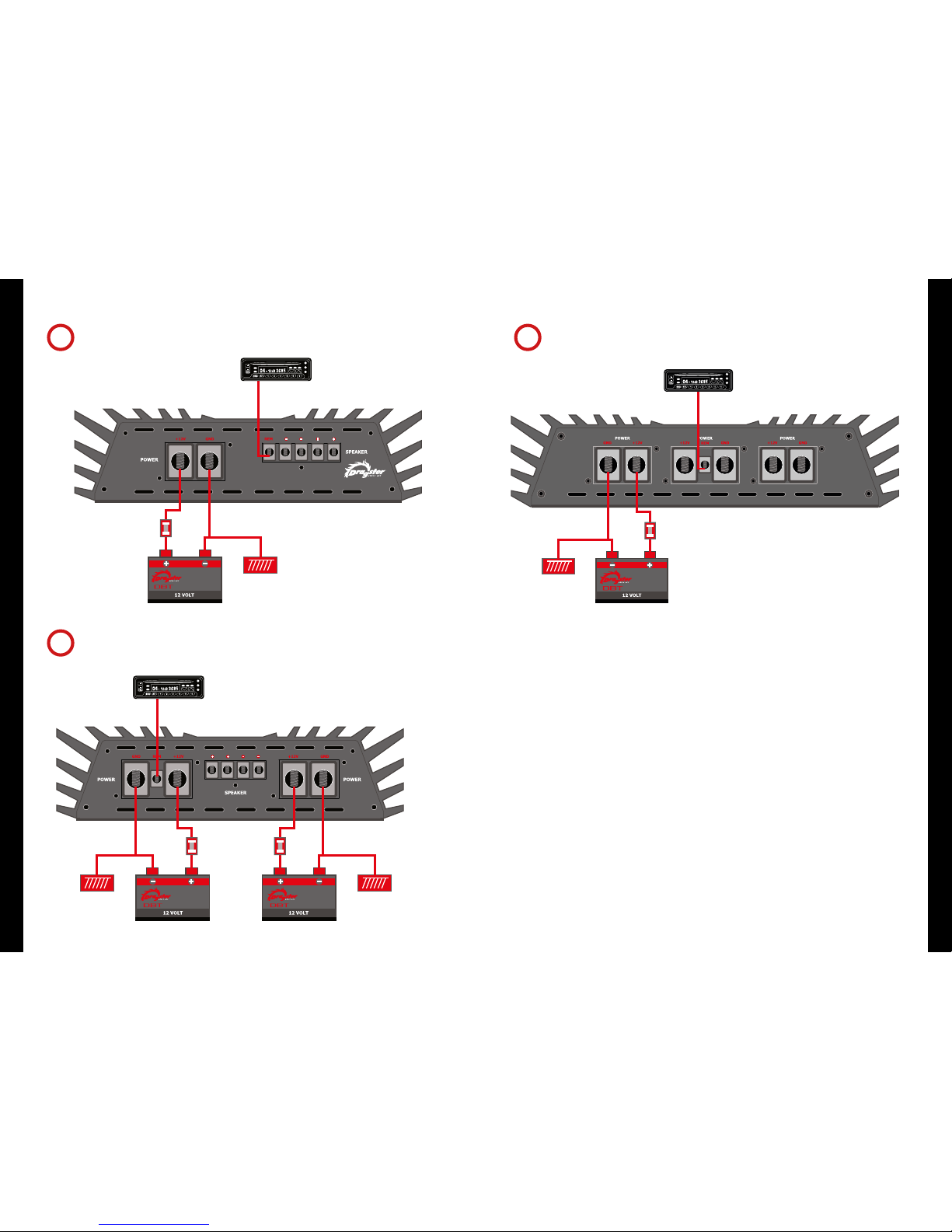
ALIMENTAzIONE E FUSIBILI
(schemi #1, #2, #3, #4, #5, #6)
AvvERTENzE GENERALI
• Per le particolari caratteristiche di elevata
potenza erogata dagli amplificatori Dragster DAF,
raccomandiamo di utilizzare cavi di alimentazione
da 35mmq o 50mmq (0 o 2 gauge). Nel caso
del DAF 7001 assicuratevi di utilizzare entrambi i
terminali di alimentazione, per il DAF 12KW i tre
terminali.
• Inserite un fusibile supplementare in linea, e
quindi in totale due, da 200A sul cavo primario di
alimentazione e da 400A per il DAF 7001, 800A per
il DAF 12KW.
• I DAF 3001, 5001 e 7001 accettano una tensione
di alimentazione fino a 16VDC erogando una
potenza maggiore. Il DAF 12KW accetta una
tensione fino a 18V.
• Prima di iniziare la installazione, scollegate il
cavo dal terminale NEGATIVO (-) della batteria.
Questa precauzione eviterà possibili corti circuiti
collegando l’amplificatore. Gli amplificatori Dragster
possono funzionare unicamente con sistemi elettrici
a 12-volt e con negativo a massa.
Raccomandiamo di proteggere il vostro sistema
audio con 2 fusibili.
Un fusibile dovrà essere collocato vicino alla
batteria dell’auto. Questo fusibile vicino alla
batteria offre una protezione contro danni da
corto circuito sul telaio dell’auto tra batteria
ed amplificatore. Un secondo fusibile collocato
più vicino all’amplificatore offre una sicurezza
supplementare all’amplificatore stesso.Il cavo rosso
di alimentazioni con i fusibili inseriti deve essere
collegato al terminale positivo dell’amplificatore
(12V+).
Un secondo cavo nero (o blue o trasparente)
di uguale sezione deve essere utilizzato quale
cavo di massa e fissato ad un punto del telaio.
Assicuratevi che non vi sia vernice od altro
isolante che impedisca un contatto ottimale al
telaio. Installando altri amplificatori, montateli in
prossimità del primo così da utilizzare il medesimo
collegamento a massa. Collegate il cavo di massa
al terminale dell’amplificatore contrassegnato con
GND (ground).
Raccomandiamo di utilizzare cavi ed accessori
Dragster studiati appositamente per installazioni
di qualità.
A volte accade di osservare una fusione dei
terminali di alimentazione o di massa. Ciò è
causato da un cattivo collegamento di massa.
Infatti, verificandosi una situazione di questo tipo,
il calore interviene sul punto più debole che è
costituito dalle viti dei terminali dell’amplificatore e
dopo un certo tempo inizia a fondere il terminale.
E’ buona prassi toccare i cavi di alimentazione e di
massa con le mani in prossimità dell’amplificatore
dopo che questo è stato messo in funzione da
un certo tempo. Se i cavi sono caldi al tatto,
probabilmente avete una cattiva connessione. Se
siete certi delle connessioni ed i cavi continuano
ad essere caldi, dovete intervenire maggiorando la
sezione dei cavi.
Il terminale REMOTE TURN ON è collocato vicino
alle connessioni di alimentazione (+12V) e di
massa (GND). Questa connessione consente
l’accensione e lo spegnimento dell’amplificatore
unitamente al resto del sistema. Il collegamento
viene effettuato mediante un cavo di sezione
ridotta e deve raggiungere l’uscita per l’antenna
motorizzata sulla radio o l'uscita appositamente
dedicata. Qualora la radio non disponga di una
idonea uscita, potete collegare il terminale REMOTE
ad una uscita per accessori che sia sotto blocchetto
di accensione.
CONNESSIONI RCA
Collegate i cavi segnale dalla sorgente sonora
all’ingresso dell’amplificatore. Suggeriamo di
utilizzare cavi schermati RCA della migliore qualità
per eliminare o ridurre indesiderati disturbi
al vostro sistema. Ad evitare disturbi elettrici
che potrebbero entrare nel sistema, abbiate
l’avvertenza di stendere i cavi sul lato opposto
del veicolo rispetto a quello utilizzato per i cavi di
alimentazione dell’amplificatore.
• Uscita RCA preamplificata (DAF 2502/4002/
3001/5001/7001/12KW). L’uscita preamplificata è
un segnale non filtrato mixato da entrambi i canali
di ingresso. Usate questo segnale per alimentare
un amplificatore supplementare nel vostro sistema.
• Ingressi RCA 4 canali (DAF 1004/1754). Hanno
4 terminali di ingresso RCA che consentono di
accettare 4 canali bilanciati sotto fader dalla vostra
autoradio. Se la autoradio ha una sola coppia di
RCA in uscita, utilizzate uno sdoppiatore ad “Y”
per dividere il segnale sui 4 connettori di ingresso.
CONNESSIONI ALTOPARLANTI
AvvERTENzE GENERALI
• Un amplificatore Dragster DAF è estremamente
potente e può danneggiare seriamente qualsiasi
altoparlante che non sia stato progettato per
accogliere tali potenze. Pertanto assicuratevi che i
dati di potenza e di impedenza dell’altoparlante
da collegare siano compatibili con quelli
dell’amplificatore.
• I terminali altoparlanti accettano cavi sino ad
8mmq (8 gauge).
DAF 3001 / DAF 5001 / DAF 7001 /
DAF 12KW
1 CANALE CLASSE “D”
• Configurazione con subwoofer ad 1-ohm
(schema #7, #8)
•Configurazione con due amplificatori collegati a
ponte (schema #9)
• Livello di ingresso, filtro subsonico, livello dei
bassi sono controllati unicamente dall’amplificatore
Master.
• La completa sezione di preamplificazione
dell’amplificatore Sleve viene by-passata e
segue automaticamente quanto viene impostato
sull’amplificatore Master assicurando un perfetto
allineamento del sistema. Anche il controllo a
distanza dei bassi viene operato con un unico
controllo collegato all’amplificatore Master
semplificando anche la installazione.
• Utilizzate l’uscita preamplificata RCA
dell’amplificatore Master per l’eventuale
collegamento ad altri amplificatori del sistema.
• Posizionate il deviatore dell’amplificatore Master
su MASTER e Slave su SLAVE.
• Il controllo di fase (PHASE) deve essere nella
medesima posizione per entrambi gli amplificatori.
• Posizionate i valori di crossover, filtro subsonico
e toni bassi sull’amplificatore MASTER secondo
quanto desiderato.
• Utilizzate un normale connettore RCA per
collegare MASTER OUT dell’amplificatore #1
(Master) a SLAVE IN dell’amplificatore #2 (Slave).
• Collegate un cavo per altoparlanti ad elevata
sezione tra i terminali altoparlanti con polo
negativo (-) di entrambi gli amplificatori.
• Collegando a ponte due amplificatori DAF, la
impedenza finale non scenderà sotto 2-ohm.
• Il collegamento a ponte deve assolutamente
essere fatto tra due amplificatori di uguale
modello.
CONTROLLI
(schema #18)
• CROSSOVER PASSA-BASSO 24dB. Avendo passi da
24dB per ottava, il crossover pass-basso assicura
che solo le frequenze più basse dall’amplificatore
vengano riprodotte.
• FILTRO SUBSONICO REGOLABILE. Questi
amplificatori hanno un filtro subsonico con
regolazione da 10Hz a 50Hz. Il filtro passa-alto è
particolarmente utile quando si utilizzano le casse
reflex. Il filtro subsonico deve essere posizionato su
una frequenza tale da evitare il funzionamento del
sub in sovra escursione.
• EQUALIZZATORE BASSI. L’amplificatore include un
equalizzatore bassi con una frequenza centrale a
45Hz che può essere regolata sino ad un aumento
di 9dB.
• CONTROLLO DI FASE. Il controllo di fase regolabile
da 0 a 180oconsente una regolazione fine dei
toni bassi per un perfetto allineamento con gli
altoparlanti delle medie ed alte frequenze.
• INDICATORI A LED DI CONTROLLO ACCENSIONE
E DIAGNOSTICA. Gli amplificatori DAF hanno un
sofisticato sistema di protezione controllato da
un circuito IC. Qualora l’amplificatore entrasse in
stato di diagnosi per un sovraccarico termico o per
un corto circuito sugli altoparlanti, l’amplificatore
viene disattivato e tale condizione è segnalata
dall’accensione del LED.
DAF 2502 / DAF 4002
2 CANALI
• Configurazione base stereo (schema #10, #13)
•Configurazione a ponte subwoofer a 2-ohm
(schema #11, #14)
•Configurazione con quattro subwoofer 4-ohm
(schema #12, #15 )
CONTROLLI
(schema #19, #20)
DAF 1004 / 1754
4 CANALI A POTENZA DIFFERENZIATA
• Configurazione stereo a 2-ohm
(schema #16)
•Configurazione base a 3-canali a 2-ohm
(schema #17)
CONTROLLI
(schema #21)
• CONFIGURAZIONE PASSA-BANDA.
I DAF 2502/4002 sui canali 1 e 2 ed i DAF
1004/1754 sia sui canali 1/2 che 3/4 possono
essere configurati in passa-banda ognuno con
un proprio campo di frequenze. Posizionando
entrambi i filtri passa-alto e passa-basso su ON,
potete ora tagliare le frequenze sia in alto che in
basso.
• MOLTIPLICATORE DI FREQUENZE CROSSOVER.
I DAF multicanale hanno su tutti i canali un
crossover completamente regolabile.
Per i 2 canali il campo va da 15Hz a 400Hz per il
passa-alto; premendo il moltiplicatore x10, varia il
campo da 150Hz a 4kHz. Analogamente il passa-
basso può essere variato da 40Hz-400Hz a 400Hz-
4kHz. Ciò è particolarmente utile per configurazioni
passa-banda.
Per i 4 canali le frequenze passa-alto vanno
da 20Hz a 800Hz, per il passa-basso da 50Hz
a 800Hz. Entrambi possono usufruire di un
moltiplicatore x10.
• FILTRAGGIO SUBSONIC SUI DAF A 4 CANALI
(canali 3 e 4). Posizionate il filtro passa-alto su ON
e regolate la frequenza tra 15Hz e 30Hz.
• INDICATORI A LED DI CONTROLLO ACCENSIONE
E DIAGNOSTICA. Gli amplificatori DAF hanno un
sofisticato sistema di protezione controllato da
un circuito IC. Qualora l’amplificatore entrasse in
stato di diagnosi per un sovraccarico termico o per
un corto circuito sugli altoparlanti, l’amplificatore
viene disattivato e tale condizione è segnalata
dall’accensione del LED.
TARATURA
Quando il sistema è operative, la prima cosa
da fare è sistemare approssimativamente tutte
le posizioni di crossover. Ad esempio, nella
configurazione base di un sistema subwoofer dei
monoblock, sistemate a circa 100Hz il filtro passa-
basso ed il controllo di equalizzazione dei bassi a
0 (risposta piatta).
Ora dovrete sistemare il livello segnale di ingresso.
La manopola indicata con GAIN regola il livello di
ingresso da 200mV a 6V (DAF 3001/5001/7001/
12KW) o 300mV a 8V (DAF multicanale).
La regolazione avviene girando la manopola sul
valore minimo a fondo corsa in senso antiorario
con un piccolo cacciavite. Abbiate l’avvertenza di
non provocare alcuna pressione o forzatura. Quindi
regolate il volume della radio al massimo. Ora
girate la manopola GAIN in senso orario verso il
valore massimo. Quando avvertire una distorsione
nel suono, tornate leggermente indietro ed il
vostro amplificatore è tarato. Può essere utile
usufruire di una seconda persona che vi aiuti a
tarare il livello.
Quando tarate un sistema con più amplificatori,
intervenite su ogni amplificatore separatamente.
Iniziate con l’amplificatore dedicato ai bassi, quindi
procedete con quello(i) dedicato(i) ai toni alti.
Quando siete soddisfatti della taratura dei livelli,
utilizzate qualsiasi controllo di equalizzazione per
sistemare il livello di toni del sistema secondo
la vostra personale preferenza. Ricordate che
una volta sistemata la equalizzazione, occorre
risistemare i controlli di livello.
Il controllo di livello di ogni amplificatore car
audio non deve essere utilizzato quale controllo
di volume. Infatti si tratta di un sofisticato
componente progettato per interfacciare il livello
di uscita della vostra autoradio con il livello di
ingresso dell’amplificatore. Non posizionate il
livello di ingresso dell’amplificatore al massimo
senza che il metodo di regolazione lo richieda.
Il vostro sistema audio può essere molto sensibile
ai disturbi se il LIVELLO è tarato sul massimo e
non si interfaccia con il segnale di ingresso. Le
regolazioni di livello vengono effettuate una sola
volta alla taratura iniziale del sistema.Se il vostro
sistema è stato installato da un professionista non
variate le regolazioni da lui impostate, si tratta
appunto di un professionista!
italiano

14 1514 15
DAF 3001 / 5001 POWER, GROUND & REMOTE CONNECTION DIAGRAM
#1
DAF 7001 POWER, GROUND & REMOTE CONNECTION DIAGRAM
#2
FUSE 200 A
FUSE 400 A FUSE 400 A
#3
REMOTE TURN-ON
FUSE 800A
MAIN BATTERY
DAF 12KW POWER, GROUND & REMOTE CONNECTION DIAGRAM
power, ground & remote connection diagram - 1 CHANNEL

16 17
FUSE 200 A
16 17
power, ground & remote connection diagram - 2 CHANNEL
power, ground & remote connection diagram - 4 CHANNEL
DAF 4002 POWER, GROUND & REMOTE CONNECTION DIAGRAM
DAF 1004 / DAF 1754 POWER, GROUND & REMOTE CONNECTION DIAGRAM
#5
#6
DAF 2502 POWER, GROUND & REMOTE CONNECTION DIAGRAM
#4
FUSE 200 A FUSE 200 A

18 19
speaker wiring configuration - 1 CHANNEL
DAF 3001 / DAF 5001 / DAF 7001 1-OHM MONO LOAD WIRING
#7
2 OHM FINAL WOOFER LOAD
DVC 2 OHM WIRED IN PARALLEL = 1 OHM
2 OHM FINAL WOOFER LOAD
OR
TO AMP +
TO AMP –
#8 DAF 12KW 1-OHM MONO LOAD WIRING
1 ˜8 OHMS
2 ˜8 OHMS
2 ˜8 OHMS

20 21
speaker wiring configuration - 1 CHANNEL
DAF 3001 / DAF 5001 / DAF 7001 BRIDGING TWO MONO CHANNEL AMPLIFIERS DAF 12KW BRIDGING TWO MONO CHANNEL AMPLIFIERS
#9
Use heavy gauge wire to connect both amplifiers speaker negative (-) connection.
When bridging two DAF mono amplifiers, the final impedance of the bridged channel
shall be not less trhan 2-ohm.
Under no circumstances can you bridge different models of amplifiers.
POSITIVE TERMINAL OF WOOFER TO
MASTER AMPLIFIER POSITIVE TERMINAL
2-OHM FINAL IMPEDANCE LOAD
RCA HEAD UNIT SIGNAL TO MASTER AMP ONLY!
MASTER AMP IN MASTER MODE
RCA CABLE: fully adjusted signal
is transferred from Master to Slave amp
NO RCA CABLES TO BE ATTACHED TO SLAVE AMP SLAVE AMP IN SLAVE MODE
MINUS TERMINAL OF WOOFER TO
SLAVE AMPLIFIER POSITIVE TERMINAL
DAF 12KW - MASTER AMPLIFIER
DAF 12KW - SLAVE AMPLIFIER 2 ˜8 OHMS
DAF 12 KW. AMPLIFIER’S SINGLE UNIT MINIMUM IMPEDANCE IS 1 OHM.
LINKED MINIMUM IMPEDANCE IS 2 OHM. WORKING VOLTAGE IS 9V˜16V
CAUTION!
POSITIVE TERMINAL
OF WOOFER
TO MASTER AMPLIFIER
POSITIVE TERMINAL
MINUS TERMINAL
OF WOOFER
TO SLAVE AMPLIFIER
POSITIVE TERMINAL
MASTER AMP IN MASTER MODE
SLAVE AMP IN SLAVE MODE
RCA HEAD UNIT SIGNAL
TO MASTER AMP ONLY!

22 2322 23
#10
speaker wiring configuration - 2 CHANNEL
DAF 2502 BASIC 2 CHANNEL CONFIGURATION
# 11 DAF 2502 2-OHM BRIDGED SUBWOOFER #12 DAF 2502 FOUR 4-OHM SUBWOOFERS
MIDRANGE MIDRANGE
TWEETERTWEETER
CROSSOVER CROSSOVER
BAND PASS FROM 10OHz - 4KHz
HIGH PASS SWITCH SETTINGS
BAND PASS FROM 2OHz - 100Hz
SUBWOOFER SWITCH SETTINGS
SUBWOOFER BAND PASS WILL ACT AS SUBSONIC FILTER
DVC 4 OHM WOOFER IN PARALLEL
OR 2 OHM WOOFER
#10
BAND PASS FROM 2OHz - 100Hz
SUBWOOFER SWITCH SETTINGS
TWO 4 OHM SUBWOOFER WIRED
IN PARALLEL TO EACH CHANNEL WITH
EQUAL A 2 OHM MONO LOAD

24 25
#13
speaker wiring configuration - 2 CHANNEL
DAF 4002 BASIC 2 CHANNEL CONFIGURATION
#14 DAF 4002 2-OHM BRIDGED SUBWOOFER #15 DAF 4002 FOUR 4-OHM SUBWOOFERS
MIDRANGE MIDRANGE
TWEETERTWEETER
CROSSOVER CROSSOVER
BAND PASS FROM 10OHz - 4KHz
HIGH PASS SWITCH SETTINGS
BAND PASS FROM 2OHz - 100Hz
SUBWOOFER SWITCH SETTINGS
SUBWOOFER BAND PASS WILL ACT AS SUBSONIC FILTER
DVC 4 OHM WOOFER IN PARALLEL
OR 2 OHM WOOFER
#13
BAND PASS FROM 2OHz - 100Hz
SUBWOOFER SWITCH SETTINGS
TWO 4 OHM SUBWOOFER WIRED
IN PARALLEL TO EACH CHANNEL WITH
EQUAL A 2 OHM MONO LOAD

speaker wiring configuration - 4 CHANNEL
26 27
#16 DAF 1004 / DAF 1754 2-OHM STEREO LOAD
MIDRANGE
CROSSOVER CROSSOVER
TWEETER
4-OHM TWEETER IN PARALLEL
TWEETER
TWEETER
TWEETER
= 2-OHM STEREO LOAD
MIDRANGE MIDRANGE MIDRANGE
4-OHM MIDRANGE
= 2-OHM STEREO LOAD
BAND PASS FROM 400Hz - 4KHz CHANNEL 3 AND 4
BAND PASS SWITCH SETTINGS
HIGH PASS FROM 4KHz CHANNELS 1 AND 2
HIGH PASS SWITCH SETTINGS
Four 4-Ohm speakers installed in parallel.
Do not mix impedances and do not run amp below 2-Ohm stereo load per channel
#17 DAF 1004 / DAF 1754 BASIC 3-CHANNEL CONFIGURATION
The DAF 1004 is classified as an unbalanced amplifier as the power of channels 1/2 is not equal to the power of channels 3/4.
Its purpose and design was to deliver optimum 3-channel system performance. All channels are 1-Ohm stable in stereo mode and you may be bridged
to a 2-Ohm.
CROSSOVER
MIDRANGE
TWEETER
CROSSOVER
TWEETER
= 2-OHM STEREO LOAD
SUBWOOFER
DVC 2-OHM WOOFER WIRED IN SERIES TO 4-OHM
SUBWOOFER
= 2-OHM BRIDGED
MIDRANGE
BAND PASS FROM 20Hz - 100Hz CHANNEL 3 AND 4
SUBWOOFER SWITCH SETTINGS
BAND PASS FROM 100Hz - 4KHz CHANNELS 1 AND 2
HIGH PASS SWITCH SETTINGS

controls
controls
28 29
CONTROLS DAF 3001 / DAF 5001 / DAF 7001 / DAF 12KW
CONTROLS DAF 2502
#18
#19
The CROSSOVER features a step 24dB per octave
slope ensuring that only the lowest frequencies
are reproduced by the amplifier.
The adjustable PHASE CONTROL will help fine tune
your bass system to time align with midrange and high
frequency speakers.
Using the REMOTE SUBWOOFER CONTROL in a multi amp
system, the bass remote of the Master amp will control all
amps in the system. Use the proper cable supplied.
SUBSONIC FILTER especially used for vented
enclosures it should be set at vent tuning
frequency to protect against woofer unloading.
RCA head unit signal (only to Master
when bridging two amps).
The DAF amps feature an advanced input
GAIN control from 0.2 to 6V to operate
efficiently at full power from any head unit.
RCA preamp output.
The amp includes a BASS EQ with a center frequency at
45Hz which can be adjusted for up to 9dB of additional
gain at that frequency.
Controls to be used bridging
two amps in MASTER/SLAVE mode.
Power and diagnostic indicators.
CONTROLS DAF 4002
RCA head unit signal.
Set HPF and LPF to ON position and adjust to desired
frequency. On OFF position the response is full range.
Set HPF and LPF to ON position and adjust to desired
frequency. On OFF position the response is full range.
CROSSOVER MULTIPLIER: pushing multiplies
by 10 the desired frequency.
Power and diagnostic indicators.
#20
RCA preamp output.
RCA preamp output.
The DAF amps feature an advanced input
GAIN control from 0.2 to 8V to operate
efficiently at full power from any head unit.
The DAF amps feature an advanced input
GAIN control from 0.2 to 8V to operate
efficiently at full power from any head unit.
REMOTE SUBWOOFER CONTROL.
Use the supplied cable only.
CONTROLS DAF 1004 / DAF 1754
#21
RCA INPUT: allows you to have 4-ch balanced
and faded signal from your head unit.
REMOTE SUBWOOFER CONTROL.
Use the supplied cable only.
POWER AND DIAGNOSTIC indicators.
The DAF amps feature an advanced input GAIN control
from 0.2 to 8V to operate efficiently at full power from
any head unit.
Set HPF and LPF to ON position and adjust to desired
frequency. On OFF position the response is full range. RCA preamp output.

specs
specs
DAF 3001 DAF 5001 DAF 7001 DAF 12KW
RMS power @ 4ohm 14.4V W 800x1 1229x1 1746x1 2300x1
RMS power @ 2 ohm 14.4V W 1400x1 2270x1 3237x1 4400x1
RMS power @ 1ohm 14.4V W 2500x1 3926x1 5549x1 8020x1
RMS power @ 1ohm 16.0V W 3000x1 4600x1 6900x1 9880x1
RMS power @ 1ohm 18.0V W --- --- --- 12080x1
THD @ max power % <0,05 <0,05 <0,05 <0,05
frequency response @ -3dB Hz 20~230 20~230 20~230 20~230
signal/noise (weight A) dB >100 >100 >100 >100
input level adjustment 6V~200mV 6V~200mV 6V~200mV 6V~200mV
damping factor @ 100Hz # >200 >200 >250 >250
suggested on line fuse A 200 200 400 800
LP crossover frequency Hz 35~250 35~250 35~250 35~250
crossover slope dB/oct 24 24 24 24
phase o0~180 0~180 0~180 0~180
variable bass boost @ 45Hz dB 0~9 0~9 0~9 0~9
variable subsonic filter Hz 10~50 10~50 10~50 10~50
remote sub level control yes yes yes yes
RCA line out yes yes yes yes
dimension (WxHxL) mm 260x69x400 260x69x540 260x69x650 300x71x880
SPECS
DAF 2502 DAF 4002 DAF 1004 DAF 1754
RMS power @ 4ohm 14.4V W 250x2 400x2 100x4 175x4
RMS power @ 2ohm 14.4 V W 450x2 700x2 180x4 300x4
RMS power @ 1ohm 14.4V W 625x2 1000x2 --- ---
RMS power @ 4ohm bridge 14.4V W 900x1 1400x1 450x2 700x2
RMS power @ 2ohm bridge 14.4V W 1300x1 2000x1 --- ---
THD @ max power % < 0,05 <0 ,05 < 0,05 < 0,05
frequency response @ -3dB Hz 20~30K 20~30K 20~30K 20~30K
signal/noise (weight A) dB >105 >105 >105 >105
signal voltage V 0.2~8 0.2~8 0.2~8 0.2~8
damping factor @ 100Hz # >500 >500 >500 >500
suggested on line fuse A 200 200 200 200
HP crossover frequency Hz 15~400 15~400 20~800 20~800
x10 multiplier Hz 150~4K 150~4K 200~8K 200~8K
LP crossover frequency Hz 40~400 40~400 50~800 50~800
x10 multiplier Hz 400~4K 400~4K 500~8K 500~8K
crossover slope dB/oct 24 24 24 24
variable bass boost @ 45Hz dB 0~9 0~9 0~18 0~18
remote sub level control --- --- rear channel rear channel
RCA line out yes yes yes yes
dimension (WxHxL) mm 260x69.5x400 260x69.5x670 260x69.5x350 260x69.5x540
2 CHANNEL CLASS A/B 4 CHANNEL CLASS A/B
MONOBLOCK CLASS D
3130

32
Audiocity srl - Milano - Italy
info@audiocity.it www.audiocity.it
This manual suits for next models
7
Table of contents
Languages:
Other Dragster Amplifier manuals