ii Caution Statements
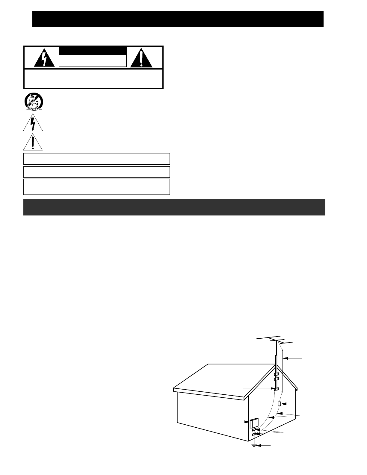
POWER SERVICE GROUNDING
ELECTRODE SYSTEM
(NEC ART 250, PART H)
GROUND
CLAMPS
GROUNDING
CONDUCTORS
(NEC SECTION
810-21)
ANTENNA
DISCHARGE
UNIT (NEC
SECTION 810-20)
ANTENNA
LEAD IN
WIRE
ELECTRIC
SERVICE
EQUIPMENT
GROUND CLAMP
EXAMPLE OF ANTENNA GROUNDING
TO REDUCE THE RISK OF FIRE OR ELECTRIC SHOCK, DO NOT EXPOSE THIS
PRODUCT TO RAIN OR MOISTURE. DO NOT OPEN THE CABINET, REFER
SERVICING TO QUALIFIED PERSONNEL ONLY.
TO PREVENT ELECTRIC SHOCK, DO NOT USE THIS (POLARIZED) PLUG WITH AN
EXTENSIONCORDRECEPTACLEOROTHEROUTLETUNLESSTHEBLADESCANBE
FULLY INSERTED TO PREVENT BLADE EXPOSURE.
POUR PREVENIR LES CHOCS ELECTRIQUES, NE PAS UTILISER CETTE FICHE
POLARISEE AVEC UN PROLONGATEUR, UNE PRISE DE COURANT OU UNE AUTRE
SORTIE DE COURANT, SAUF SI LES LAMES PEUVENT ETRE INSEREES A FOND
SANS EN LAISSER AUCUNE PARTIE A DECOUVERT.
WARNING:
CAUTION:
ATTENTION:
A product and cart combination should be moved with care. Quick
stops, excessive force and uneven surfaces may cause the product
and cart combination to overturn.
The lightning flash with arrow head symbol, within an equilateral
triangle, is intended to alert the user to the presence of uninsulated
"dangerous voltage" within the product's enclosure that may be of
sufficient magnitude to constitute a risk of electric shock to persons.
The exclamation point within an equilateral triangle is intended to
alert the user to the presence of important operating and
maintenance (servicing) instructions in the literature accompanying
the product.
!WARNING!
WARNING: TO PREVENT FIRE OR
ELECTRICAL SHOCK DO NOT
EXPOSE TO RAIN OR MOISTURE
RISK OF ELECTRIC SHOCK
DO NOT OPEN
CAUTION: TO REDUCE THE RISK OF ELECTRIC SHOCK,
DO NOT REMOVE COVER
NO USER-SERVICEABLE PARTS INSIDE
REFER SERVICING TO QUALIFIED PERSONNEL
1. Read Instructions—All the safety and operating instructions should be read before the product is
operated.
2.Retain Instructions—The safetyand operatinginstructions shouldbe retainedfor futurereference.
3. Heed Warnings—All warnings on the product and in the operating instructions should be adhered
to.
4. Follow Instructions—All operating and use instructions should be followed.
5. Cleaning—Unplug this product from the wall outlet before cleaning. Do not use liquid cleaners or
aerosol cleansers. Use a damp cloth for cleaning.
6. Attachments—Do not use attachments that are not recommended by the product manufacturer as
they may cause hazards.
7.Water andMoisture—Donot usethis productnear water—forexample, nearabathtub, washbowl,
kitchen sink or laundry tub; in a wet basement; or near a swimming pool; and the like.
8. Accessories—Do not place this product on an unstable cart, stand, tripod, bracket, or table. The
productmay fall,causing seriousinjury toachild oradult, andserious damageto theproduct. Useonly
witha cart,stand, tripod, bracket,or tablerecommended bythe manufacturer,or soldwith the product.
Any mounting of the product should follow the manufacturer's instructions, and should use a mounting
accessory recommended by the manufacturer.
9.Aproductandcartcombinationshouldbemovedwithcare.Quickstops,excessiveforce,anduneven
surfaces may cause the product and cart combination to overturn.
10. Ventilation—Slots and openings in the cabinet are provided for ventilation and to ensure reliable
operation of the product and to protect it from overheating, and these openings must not be blocked
orcovered. Theopeningsshouldnever beblockedbyplacing theproductona bed,sofa,rug,or similar
surface. This product should not be placed in a built-in installation such as bookcase or rack unless
proper ventilation is provided or the manufacturer's instructions have been adhered to.
11. Power Sources—This product should be operated only from the type of power source indicated
onthemarkinglabel. Ifyouarenotsureofthetypeofpowersuppliedtoyourhome,consultyourproduct
dealeror localpower company.For productsintended tooperate frombattery power,or othersources,
refer to the operating instructions.
12. Grounding or Polarization—This product may be equipped with a polarized alternating-current
line plug (a plug having one blade wider than the other). This plug will fit into the power outlet only one
way. This is a safety feature. If you are unable to insert the plug fully into the outlet, try reversing the
plug.Iftheplugshouldstillfailtofit,contactyourelectriciantoreplaceyourobsoleteoutlet.Donotdefeat
the safety purpose of the polarized plug.
Alternate Warnings—If this product is equipped with a three-wire grounding-type plug, a plug having
a third (grounding) pin, the plug will only fit into a grounding-type power outlet. This is a safety feature.
Ifyouareunabletoinserttheplugintotheoutlet,contactyourelectriciantoreplaceyourobsoleteoutlet.
Do not defeat the safety purpose of the grounding-type plug.
12 a. Mise à la terre ou Polarisation—Cet appareil est équipé avec un cordon d'alimentation à trois
fils. Il est a brancher sur une prise ayant un connecteur a la terre. Assurez-vous que la connection a
la terre ne manque pas.
13. Power-Cord Protection—Power-supply cords should be routed so that they are not likely to be
walked on or pinched by items placed upon or against them, paying particular attention to cords at
plugs, convenience receptacles, and the point where they exit from the product.
14.Outdoor Antenna Grounding—Ifanoutsideantennaorcable systemisconnected totheproduct,
be sure the antenna or cable system is grounded so as to provide some protection against voltage
surgesandbuilt-up staticcharges.Article810oftheNational ElectricalCode,ANSI/NFPA70, provides
informationwithregardtopropergroundingofthe mastandsupportingstructure,grounding ofthelead-
in wire to an antenna discharge unit, size of grounding conductors, location of antenna-discharge unit,
connection to grounding electrodes, and requirements for the grounding electrode. See Figure A.
15. Lightning—For added protection for this product during a lightning storm, or when it is left
unattended and unused for long periods of time, unplug it from the wall outlet and disconnect the
antenna or cable system. This will prevent damage to the product due to lightning and power-line
surges.
16. Power Lines—An outside antenna system should not be located in the vicinity of overhead power
lines, other electric light or power circuits, where it can fall into such power lines or circuits. When
installing an outside antenna system, extreme care should be taken to keep from touching such power
lines or circuits as contact with them may be fatal.
17. Overloading—Do not overload wall outlets, extension cords, or integral convenience receptacles
as this can result in a risk of fire or electric shock.
18. Object and Liquid Entry—Never push objects of any kind into this product through openings as
they may touch dangerous voltage points or short-out parts that could result in a fire or electric shock.
Never spill liquid of any kind on the product.
19. Servicing—Do not attempt to service this product yourself as opening or removing covers
may expose you to dangerous voltage or other hazards. Refer all servicing to qualified service
personnel.
20. Damage Requiring Service—Unplug this product from the wall outlet and refer servicing to
qualified service personnel under the following conditions:
a. When the power-supply cord or plug is damaged,
b. If liquid has been spilled, or objects have fallen into the product,
c. If the product has been exposed to rain or water,
d. If the product does not operate normally by following the operating instructions. Adjust only
those controls that are covered by the operating instructions as an improper adjustment of other
controls mayresult in damageand willoften requireextensive work bya qualifiedtechnician torestore
the product to its normal operation,
e. If the product has been dropped or damaged in any way, and
f. When the product exhibits a distinct change in performance—this indicates a need for service.
21. Replacement Parts—When replacement parts are required, be sure the service technician has
used replacement parts specified by the manufacturer or have the same characteristics as the original
part. Unauthorized substitutes may result in fire, electric shock or other hazards.
22.Safety Check—Uponcompletionofanyserviceorrepairstothisproduct,asktheservicetechnician
to perform safety checks to determine that the product is in proper operating condition.
23. Wall or Ceiling Mounting—The product should be mounted to a wall or ceiling only as
recommended by the manufacturer.
24. Heat—The product should be situated away from heat sources such as radiators, heat registers,
stoves, or other products (including amplifiers) that produce heat.
NOTE TO CATV SYSTEM INSTALLERS:
THISREMINDERIS PROVIDED TO CALL THE CATV SYSTEM INSTALLER'S ATTENTION
TO ARTICLE 820 - 40 OF THE NEC THAT PROVIDES GUIDELINES FOR PROPER
GROUNDING AND, IN PARTICULAR, SPECIFIES THAT THE CABLE GROUND SHALL BE
CONNECTED TO THE GROUNDING SYSTEM OF THE BUILDING, AS CLOSE TO THE
POINT OF CABLE ENTRY AS PRACTICAL.
Important Safety Instructions