Draper 32301 User manual
CONTACTS
– DRAPER TOOLS LIMITED,
Hursley Road, Chandler's Ford,
Eastleigh, Hampshire. SO53 1YF. U.K.
– Helpline: (023) 8049 4344
– Sales Desk: (023) 8049 4333
– Internet: www.drapertools.com
– Sales Fax: (023) 8049 4209
–General Enquiries: (023) 8026 6355
– Service/Warranty Repair Agent
For aftersales servicing or warranty repairs, please
contact the Draper Tools Helpline for details of an
agent in your local area.
YOUR DRAPER STOCKIST
KCCH0217
©Published by Draper Tools Limited.
No part of this publication may be reproduced, stored in a retrieval system or
transmitted in any form or by any means, electronic, mechanical photocopying,
recording or otherwise without prior permission in writing from Draper Tools Ltd.
IMPORTANT: PLEASE READ THESE INSTRUCTIONS CAREFULLY TO ENSURE THE
SAFE AND EFFECTIVE USE OF THIS PRODUCT.
INSTRUCTIONS
These instructions accompanying the product are the original instructions. This document is part of the product,
keep it for the life of the product passing it on to any subsequent holder of the product. Read all these
instructions before assembling, operating or maintaining this product.
This manual has been compiled by Draper Tools describing the purpose for which the product has been
designed, and contains all the necessary information to ensure its correct and safe use. By following all the
general safety instructions contained in this manual, it will ensure both product and operator safety, together
with longer life of the product itself.
AlI photographs and drawings in this manual are supplied by Draper Tools to help illustrate the operation of the
product.
Whilst every effort has been made to ensure the accuracy of information contained in this manual, the Draper
Tools policy of continuous improvement determines the right to make modifications without prior warning.
PETROL
BLOWER/
VAC
32301

1. TITLE PAGE
1.1 INTRODUCTION:
USER MANUAL FOR: Petrol Blower Vac
Stock No: 32301
Part No: BVP26
As our user manuals are continually updated, users should make sure that they use
the very latest version.
Downloads are available from: http://www.drapertools.com/manuals
Draper Tools Limited
Hursley Road
Chandler’s Ford
Eastleigh
Hampshire
SO53 1YF
UK
Website: drapertools.com
Product Helpline: +44 (0) 23 8049 4344
General Fax: +44 (0) 23 8026 0784
1.3 UNDERSTANDING THIS MANUALS SAFETY CONTENT:
WARNING! – Information that draws attention to the risk of injury or death.
CAUTION! – Information that draws attention to the risk of damage to the product or
surroundings.
1.4 COPYRIGHT © NOTICE:
Copyright © Draper Tools Limited.
Permission is granted to reproduce this publication for personal and educational use
only. Commercial copying, redistribution, hiring or lending is prohibited.
No part of this publication may be stored in a retrieval system or transmitted in any
other form or means without written permission from Draper Tools Limited.
In all cases this copyright notice must remain intact.
1.2 REVISIONS:
Date first published May 2017.
- 23 -
NOTES

2. CONTENTS
1. TITLE PAGE
1.1 INTRODUCTION.......................................................................................................... 2
1.2 REVISION HISTORY .................................................................................................. 2
1.3 UNDERSTANDING THIS MANUAL ............................................................................. 2
1.4 COPYRIGHT NOTICE ................................................................................................. 2
2. CONTENTS
2.1 CONTENTS .................................................................................................................... 3
3. GUARANTEE
3.1 GUARANTEE ...............................................................................................................4
4. INTRODUCTION
4.1 SCOPE......................................................................................................................... 5
4.2 SPECIFICATION .......................................................................................................... 5
4.3 HANDLING AND STORAGE ........................................................................................ 5
5. HEALTH AND SAFETY INFORMATION
5.1 SPECIFIC SAFETY INSTRUCTION FOR PETROL BLOWER/VAC’S ........................ 6
–¬Service..................................................................................................................... 6
5.2 HEALTH AND SAFETY INFORMATION CONCERNING THE USE OF FUELS ........6
6. TECHNICAL DESCRIPTION
6.1 IDENTIFICATION ......................................................................................................... 8
7. UNPACKING AND CHECKING
7.1 PACKAGING ............................................................................................................... 9
7.2 WHAT’S IN THE BOX.................................................................................................. 9
8. ASSEMBLING THE PETROL BLOWER/VAC
8.1 ASSEMBLING THE BLOWER TUBES ..................................................................... 10
8.2 ASSEMBLING THE VACUUM TUBES....................................................................... 11
8.3 ATTACHING THE COLLECTION BAG ..................................................................... 12
8.4 ATTACHING THE CARRYING STRAP ..................................................................... 12
9. OPERATING INSTRUCTIONS
9.1 FUELLING..................................................................................................................13
9.2 COLD STARTING THE ENGINE................................................................................ 14
9.3 WARM STARTING THE ENGINE .............................................................................. 15
9.4 STOPPING THE ENGINE .......................................................................................... 16
9.5 ADJUSTING THE ENGINE IDLE SPEED..................................................................16
9.6 USING THE BLOWER/VAC ....................................................................................... 17
–¬Blower Operation ................................................................................................. 17
–¬Vacuum Operation................................................................................................ 17
10. MAINTENANCE AND TROUBLESHOOTING
10.1 CLEANING THE AIR FILTER ..................................................................................... 18
10.2 SPARK PLUG MAINTENANCE ................................................................................. 18
10.3 CLEANING THE FUEL FILTER.................................................................................. 19
10.4 TROUBLESHOOTING GUIDE................................................................................... 19
10.5 CLEANING AND MAINTENANCE OVERVIEW.........................................................20
10.6 STORING THE MACHINE FOR AN EXTENDED PERIOD OF TIME ........................ 20
11. EXPLANATION OF SYMBOLS
11.1 EXPLANATION OF SYMBOLS ................................................................................... 21
12. DISPOSAL
12.1 DISPOSAL ................................................................................................................. 22
DECLARATION OF CONFORMITY .............................................................................. ENCLOSED
12.1 DISPOSAL
– At the end of the machine’s working life, or when it can no longer be repaired, ensure that it is
disposed of according to national regulations.
– Contact your local authority for details of collection schemes in your area.
In all circumstances:
•Do not dispose of power tools with domestic waste.
•Do not incinerate.
•Do not abandon in the environment.
•When decommissioning (preparing the machine to be scrapped) drain any remaining fuel
and oil for separate disposal.
- 22 -
12. DISPOSAL
- 3 -

3. GUARANTEE
3.1 GUARANTEE
Draper tools have been carefully tested and inspected before shipment and are guaranteed to be
free from defective materials and workmanship.
Should the tool develop a fault, please return the complete tool to your nearest distributor or
contact:
Draper Tools Limited, Chandler's Ford, Eastleigh, Hampshire, SO53 1YF. England.
Telephone Sales Desk: (023) 8049 4333 or:
Product Helpline (023) 8049 4344.
A proof of purchase must be provided with the tool.
If upon inspection it is found that the fault occurring is due to defective materials or workmanship,
repairs will be carried out free of charge. This guarantee period covering parts/labour is 12 months
from the date of purchase except where tools are hired out when the guarantee period is 90 days
from the date of purchase. The guarantee is extended to 12 months for parts only. This guarantee
does not apply to normal wear and tear, nor does it cover any damage caused by misuse, careless
or unsafe handling, alterations, accidents, or repairs attempted or made by any personnel other
than the authorised Draper warranty repair agent.
Note: If the tool is found not to be within the terms of warranty, repairs and carriage charges will be
quoted and made accordingly.
This guarantee applies in lieu of any other guarantee expressed or implied and variations of its
terms are not authorised.
Your Draper guarantee is not effective unless you can produce upon request a dated receipt or
invoice to verify your proof of purchase within the guarantee period.
Please note that this guarantee is an additional benefit and does not affect your statutory rights.
Draper Tools Limited.
- 21 -
11. EXPLANATION OF SYMBOLS
103
Warning!
Keep bystanders away.
Warning!
Risk of danger to wildlife.
Warning!
Hot surface.
Warning!
Wear suitable gloves.
Warning!
Read the instruction manual.
Warning!
Keep out of the reach of children.
Single value noise marking.
(Maximum declared
A-Weighted sound power level
in decibels).
11.1 EXPLANATION OF SYMBOLS
Danger!
Risk of flying debris.
Warning!
Wear suitable foot protection.
Warning!
Wear suitable eye/face mask
protection.
Warning!
Wear suitable ear protection.
Fuel/2-stroke oil mixture ratio.
Strictly no naked flames or
smoking near the appliance.
Choke closed.
Choke open.
Danger from rotating impeller.
- 4 -

4. INTRODUCTION
4.1 SCOPE
This product is designed for blowing fallen leaves and other loose green matter prior to collection.
This product is designed for use in the domestic environment only.
4.2 SPECIFICATION
Stock No: ................................................................................................................................. 32301
Part No: .................................................................................................................................. BVP26
Engine displacement ............................................................................................................... 25.4cc
Maximum revolutions per min. (no load) ........................................................................... 7,000min-1
Maximum revolutions per min. at idle (no load)................................................................. 3,200min-1
Fuel tank capacity ..................................................................................................................... 0.65L
Fuel mixture...............................................................................................................................30:1††
Carburettor ................................................................................... Diaphragm type with primer pump
Spark plug .................................................................................................................................... L7T
Air flow:
Maximum air speed (blowing) ............................................................................. 75m/s (270km/h)
Maximum air speed (vacuuming)................................................................................... 6.3m3/min
Sound pressure level.............................................................................................................86dB(A)
Sound power level...............................................................................................................103dB(A)
Single value noise level (LWA)†...........................................................................................103dB(A)
Vibration level ................................................................................................................. 5.5±1.5m/s2
Dimensions (assembled) (L
×
W
×
H) ................................................................1210
×
520
×
360mm
Weight (dry, with vacuum tubes) ............................................................................................... 5.4kg
†A-weighted sound pressure level in accordance to 2000/14/EC.
††Use semi-synthetic 2 stroke oil.
4.3 HANDLING AND STORAGE
Care must still be taken when handling and lifting. Dropping this machine will have an effect on the
accuracy and may also result in personal injury. This machine is not a toy and must be respected.
The environment will have a negative result on its operation if you are not careful. If the air is
damp, components will rust. If the machine is unprotected from dust and debris; components will
become clogged: And if not cleaned and maintained correctly or regularly the machine will not
perform at its best.
- 5 -- 20 -
10. MAINTENANCE AND TROUBLESHOOTING
10.4 TROUBLESHOOTING GUIDE (continued)
10.5 CLEANING AND MAINTENANCE OVERVIEW
Fault Possible cause Remedy
The motor does not
reach its maximum
speed.
Important: Please note, all repairs/servicing should be carried out by a qualified person.
1. The air filter is dirty.
2. The spark plug is dirty.
3. The distance between
the electrodes of the
spark plug is too large.
4. Wrong fuel.
1. Clean the air filter.
2. Clean the spark plug.
3. Set the gap to 0.6 to 0.7mm.
4. Drain the tank and fill with the
correct fuel.
Prior to every start.
Every 10 operating hours (more frequently in dusty conditions).
Every 10/15 operating hours.
Every 50 operating hours. (more frequently for reduced engine performance).
1. Check/clean/replace air filter element.
2. Check the pull starter for damage to the
starter .
3. Checking threaded connections for
tightness.
4. Remove dirt and debris from the
machine’s exterior
5. Inspect engine cooling fins for
accumulations of dirt and debris, clean as
necessary.
1. Check/clean/replace air filter element.
1. See section 10.1.
2. Visual inspection/testing.
3. Visual inspection/testing.
4. Visual inspection.
5. Visual inspection.
1. Check/clean/replace spark plug. 1. See section 10.2.
1. Inspect the entire machine and tubes for
damage, including loose or missing
components and repair as necessary.
2. Replace spark plug.
3. Inspect/replace fuel filter.
1. Visual inspection.
2. See section 10.2.
3. See section 10.3.
1. See section 10.1.
10.6 STORING THE MACHINE FOR AN EXTENDED PERIOD OF TIME
(3 MONTHS OR LONGER)
Before an extended period of disuse, you must remove the fuel from the machine.
– Drain the fuel tank, then start the engine and let it run until it stops of its own accord.

5. HEALTH AND SAFETY INFORMATION
5.1 SPECIFIC SAFETY INSTRUCTIONS FOR PETROL BLOWER/VAC’S
Warning! For your safety, please read and understand these instructions before assembling,
operating or maintaining this machine.
– Never attempt to modify or operate a modified machine. Fully assemble this machine,
including all relevant guards, before operating.
– Do not operate this machine without being completely familiar with the safety features and how
to operate them.
– Never operate this machine if the stop switch is faulty or not functioning.
– Never operate this machine while tired, ill or under the influence of drugs.
Danger! Keep out of the reach of children.
– Fully read and understand before attempting to assemble, operate or maintain the machine.
– Never allow people unfamiliar with these instructions to operate this machine. Local
regulations may restrict the age of the operator.
– Prior to each use, inspect the machine for signs of damage. Make sure the safety features are
present and functioning and that all visible nuts, bolts and screws remain tight. Vibration from
normal use can cause them to loosen over time.
– Never operate this machine with defective or missing guards.
Warning! Use of this product can pose a danger to wildlife. Before attempting to use this machine,
check the area, particularly long grass and under bushes for signs of life: if necessary relocate.
Note: Not all animals will be deterred by the noise of the product alone.
– Do not point the blower/vac nozzle in the direction of people or pets.
– Check the attachment is correctly fitted to the machine before attempting to start the engine.
Caution! As the user you are responsible for any injury to people or damage to property.
Warning! During use the engine gets very hot. Do not touch it, especially the exhaust.
– Always be aware of your surroundings, staying alert for possible hazards that you may not
hear over the noise of the engine.
– Always hold the blower/vac in your right hand, refer to the operating instructions in the manual.
– To reduce the risk of hearing loss associated with sound level, hearing protection is required.
– Wear suitable gloves to help reduce vibration fatigue.
Service
Have your power tool serviced by a qualified repair person using only identical replacement parts.
This will ensure that the safety of the power tool is maintained.
5.2 HEALTH AND SAFETY INFORMATION CONCERNING THE
USE OF FUELS
Fuels are inflammable and explosive. Reduce the risk of explosion and fire by:
– Turning off and cooling the motor down before filling the tank with fuel.
– Refraining from smoking and starting open fires when handling fuels.
– Storing and mixing fuels in approved and correspondingly labelled canisters.
10. MAINTENANCE AND TROUBLESHOOTING
10.3 CLEANING THE FUEL FILTER
The fuel tank is fitted with a filter.
– The filter is situated at the free end of the fuel pipe and can be picked out through the fuel port
with a piece of hooked wire.
– Check the fuel filter periodically. Do not allow dust to enter the fuel tank. Clogged filter will
cause difficulty when starting engine or abnormalities in engine performance.
Replace the filter if dirty.
When the inside of the fuel tank is dirty it can be cleaned by rinsing the tank out with petrol.
- 6 - - 19 -
Using the spark plug box spanner supplied
, turn the spark plug anticlockwise to
remove it.
Clean the spark plug and check the electrode
gap. Maintain a gap of 0.6 to 0.7mm.
– If required, replace the spark plug with a L7T
coded plug, or equivalent, gapped to 0.6 –
0.7mm.
Warning! Make sure you correctly seat the spark
plug thread in to the engine before screwing it
clockwise in to the head.
Fig.34
2
3
0.6mm to
0.7mm
2
3
10.4 TROUBLESHOOTING GUIDE
Fault Possible cause Remedy
Engine does not start.
Machine runs but
stutters.
1. No fuel in the tank.
2. The STOP/START switch
is in the STOP position.
3. Ignition cable plug not
firmly attached.
4. Ignition cable plug dirty.
5. Is there fuel inside the
combustion chamber.
6. The spark plug is dirty.
7. The distance between
the electrodes of the
spark plug is too large.
8. Wrong fuel.
9. Spark plug defective.
1. Is the choke set to the off
(closed) position.
1. Refuel tank.
2. Put the switch in the START
position.
3. Push the plug on tightly.
4. Clean the plug.
5. Remove the spark plug, dry off the
electrode and start at full throttle.
6. Clean the spark section.
7. Set the gap to 0.6 to 0.7mm.
8. Drain the tank and fill it with the
correct fuel.
9. Replace the spark plug.
1. Set the choke to the on (open)
position.

5. HEALTH AND SAFETY INFORMATION
Regular maintenance tasks must be carried out at
specific intervals to retain the engine's performance.
10.1 CLEANING THE AIR FILTER –
FIGS. 30 – 32
A dirty, clogged air filter will restrict the air flow in to
the engine and will cause rough running. It will
increase fuel consumption and may result in starting
problems.
Attention: Stop the engine before removing the air
filter assembly.
Pull the choke lever upwards to the closed
position to prevent any debris entering the
carburettor inlet.
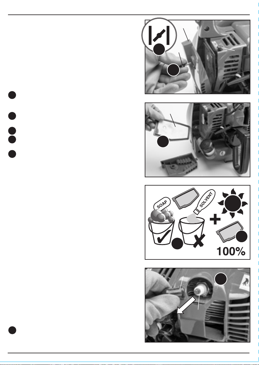
Unscrew the retaining bolt on the air filter
cover to remove it.
Remove the air filter element .
Wash the element in warm soapy water to clean
it. Do not use solvents to clean it.
Allow the filter to dry 100% before refitting it on
to the engine.
– Refit cover .
– Replace the filter if it appears worn or
damaged.
10.2 SPARK PLUG MAINTENANCE –
FIGS. 33 – 34
Over time the spark plug
can become
contaminated.
This can be due to adverse running
conditions such as, working with part throttle for a
prolonged period or a fuel mix containing too much
oil. This contamination can build up causing the
engine to run roughly, reduce the fuel consumption
or create starting problems.
Without using any tools so as to avoid damaging
the H.T. lead, remove the lead from the
back of the spark plug.
Fig.30
Fig.31
2
3
Fig.32
Fig.33
1
1
2
3
4
5
1
1
5
4
– Storing fuels in closed containers. Keeping in mind that fuels may evaporate at room
temperature and collect on the floor of closed rooms (risk of explosion).
– Start the device at least nine metres away from any stored fuels or flammable liquids.
Fuels are toxic, they contain substances that have an immediate toxic effect and may cause
permanent damage to your health. Take all precautionary measures to prevent your body from
absorbing any of these substances:
– Tank and siphon fuels only outdoors or in well-ventilated rooms.
– Do not inhale fuel fumes.
– Avoid contact with eyes and skin.
– Wear gloves when transferring fuel.
– When fuel has come into contact with your clothes, change them immediately. Clean your
clothes before putting them back on.
– Store fuels out of the reach of children.
When handled inappropriately, fuels may cause damage to the environment:
– Transfer fuel carefully. Fuel must never trickle into the ground or the sewage system.
– Dispose of any remaining fuel in an appropriate manner. Never dispose of fuel with regular
household waste.
– Fuels may be stored only for a limited time. Purchase only such quantities that can be used up
within a few months.
- 7 -
10. MAINTENANCE AND TROUBLESHOOTING
- 18 -

- 8 - - 17 -
6. TECHNICAL DESCRIPTION
6.1 IDENTIFICATION
Petrol motor unit.
Carry handle.
Throttle trigger.
ON/OFF/Ignition switch.
Blower nozzle.
Blower tube.
Vacuum air intake.
Carry strap.
Choke lever.
Recoil starter cord.
Air filter cover.
Fuel tank cap.
Fuel tank.
Side handle.
Exhaust.
Spark plug cap.
Fuel primer bulb.
Fig.28
9. OPERATING INSTRUCTIONS
9.6 USING THE BLOWER/VAC – FIGS. 27 – 29
Note: As a general rule, try to operate the machine using the lowest throttle setting necessary for
the task in hand.
Blower Operation – Figs. 27 – 28
Note: To set up the machine for blowing
applications, refer to Section 8: Assembling The
Petrol Blower/Vac.
– Use low throttle settings when clearing
lightweight materials from around lawns or
shrubbery.
– Use medium to higher throttle settings to move
lightweight grass or leaves from open areas.
– Use full throttle when moving heavy loads such
as dirt or snow.
– Machine noise increases at higher throttle
settings. Always use the lowest possible throttle
setting.
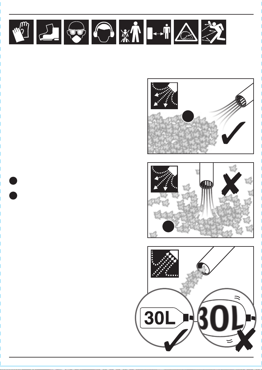
– To keep from scattering debris, blow around the
outer edges of a debris pile.
Never blow directly into the centre of a pile.
– Use rakes and brooms to loosen debris before
blowing.
– In dusty conditions, slightly dampen surface with
water (if available).
Vacuum Operation – Fig.29
Note: To set up the machine for vacuuming
applications, refer to Section 8: Assembling The
Petrol Blower/Vac.
– When using the machine in vacuuming
operation, be sure not to allow the collection
bag to become overfilled.
– Allowing the collection bag to become overfilled
will reduce the appliances effectiveness and
may cause damage to the bag itself or the
appliance.
Fig.27
Fig.29
1
2
1
2
- 16 - - 9 -
9.4 STOPPING THE ENGINE – FIG. 24
To stop the engine, move the stop switch to
the “stop” position.
Note: If the blower/vac has been running at full
speed for a prolonged period allow the engine to
idle for a few minutes before stopping.
The engine must be stopped while carrying out any
other operation such as:
– Refuelling.
– Making checks or adjustments.
– Cleaning.
9.5 ADJUSTING THE ENGINE IDLE
SPEED – FIGS. 25 – 26
Start the engine by following the steps highlighted in
the previous section: 9.2 Cold Starting the Engine.
Run the engine at idle speed until operating
temperature is reached (2 – 3 minutes).
Use the supplied screwdriver to adjust the
engine idle speed to 2300 – 2500r/min.
Turn the idle screw clockwise to increase
engine idle speed. Turn the idle screw
counterclockwise to decrease engine idle
speed.
Warning! Machine tubes and intake cover must be
installed while adjusting engine idle! Engine idle
speed will also be affected if either the intake cover
or machine tubes are blocked, damaged or
incorrectly installed.
1
1
2
3
2
9. OPERATING INSTRUCTIONS
1
Fig.24
Fig.26
Fig.25
2 – 3 mins
2300 –
2500r/min
2 – 3 mins
2
2
3
7. UNPACKING AND CHECKING
7.1 PACKAGING
Carefully remove the machine from the packaging and examine it for any sign of damage that may
have happened during shipping. Lay the contents out and check them against the parts shown
below. If any part is damaged or missing; please contact the Draper Helpline (the telephone
number appears on the Title page) and do not attempt to use the machine.
The packaging material should be retained at least during the guarantee period: in case the
machine needs to be returned for repair.
Warning! Some of the packaging materials used may be harmful to children. Do not leave any of
these materials in the reach of children.
If any of the packaging is to be thrown away, make sure they are disposed of correctly; according
to local regulations.
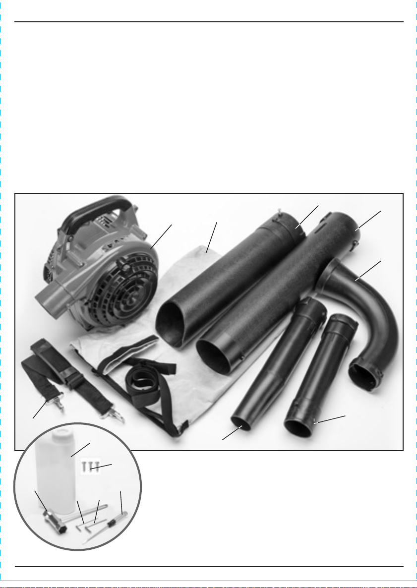
7.2 WHAT´S IN THE BOX?
As well as the blower vac, there are several parts not fitted or attached to it.
Petrol motor unit.
Blower nozzle.
Blower tube.
Carry strap.
Collection bag
intake tube.
Vacuum tube.
Vacuum nozzle.
Collection bag.
Fuel mixing bottle.
Screwdriver.
Large hex. key.
Small hex. key.
Box spanner.
M5
×
10 Screw
×
3.

- 10 - - 15 -
8. ASSEMBLING THE PETROL BLOWER/VAC
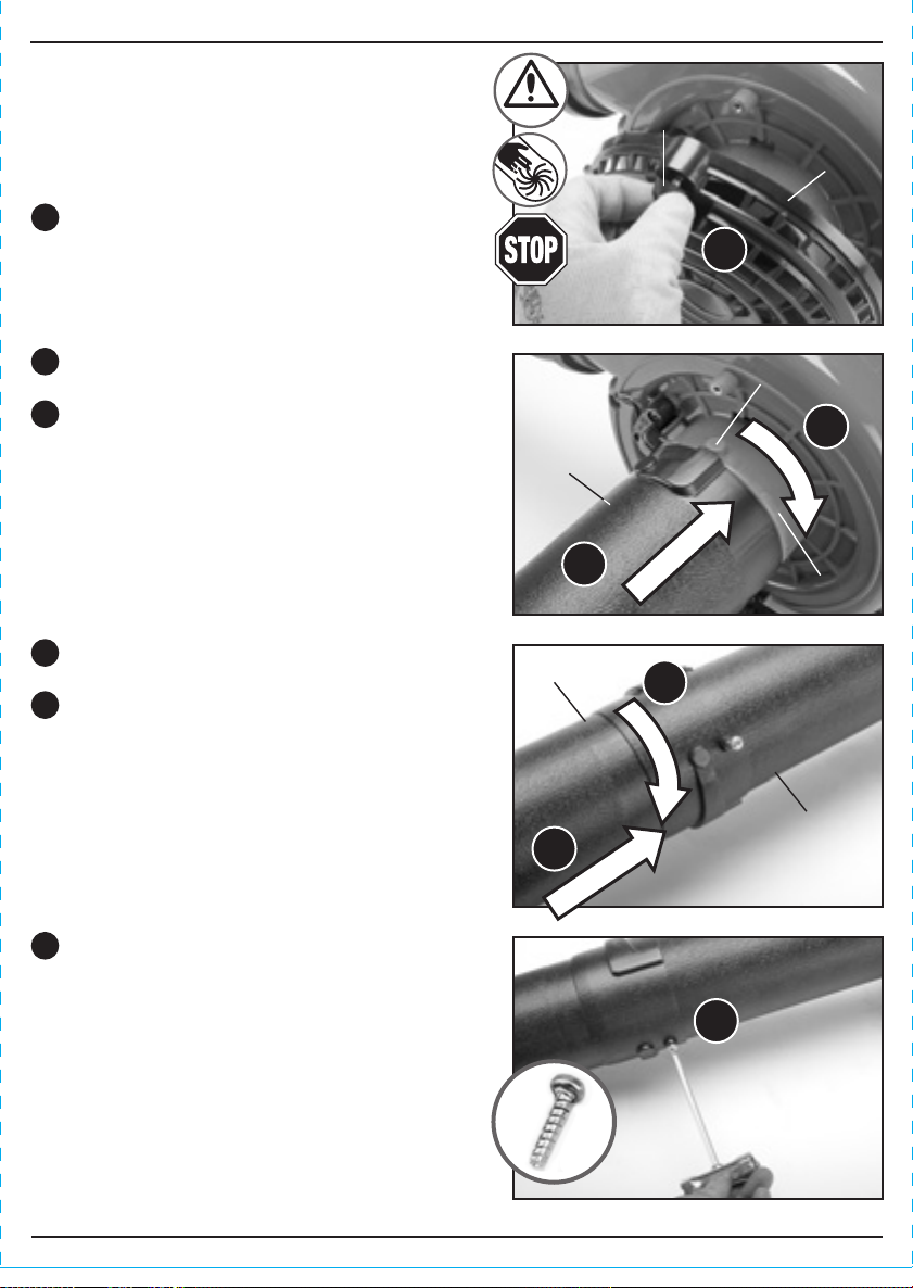
8.1 ASSEMBLING THE BLOWER
TUBES – FIGS. 1 – 3
Warning! Stop the engine and put the switch to
STOP position before installing parts, making
adjustments, cleaning or when not in use. Failure to
do so could result in possible serious injury.
Slide the blower tube over the discharge
port and locking lug .
Rotate the tube clockwise to lock in place.
Secure the blower tube in place using the
supplied M5
×
10 screw and the
screwdriver end of the box spanner .
Slide the blower nozzle on to the blower
tube and locking lug
Rotate the nozzle clockwise to lock in place.
1
2
3
4
5
Fig.1
Fig.2
Fig.3
2
3
4
5
1
Important: This petrol blower vac can switch from blowing to suction functions. This is achieved
by connecting the tubes to the correct mounting.
– For blowing function, the tube is fitted to the front outlet (see section 8.1: assembling the
blower tubes).
– For vacuum function, the collection bag is fitted to the front outlet and the main tube is fitted to
the mounting that is accessed by opening the vented side cover (see section 8.2: assembling
the vacuum tubes).
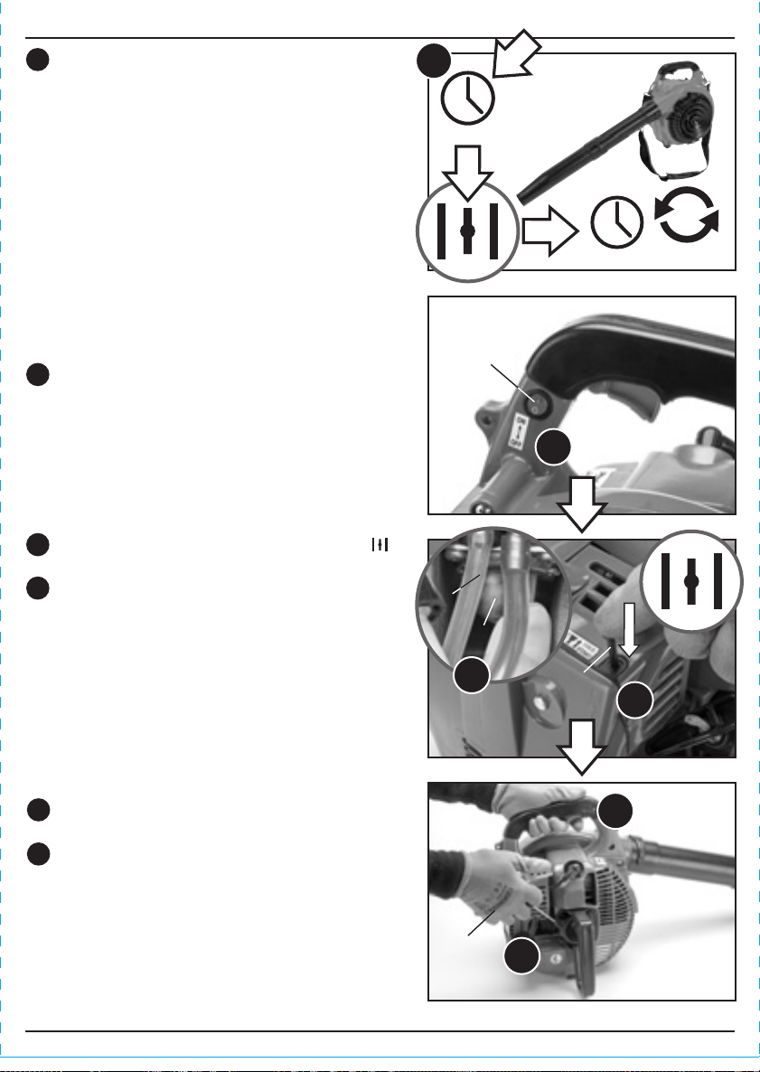
Once the motor has started, allow the motor to
warm up for a few minutes before commencing
operation.
7
9. OPERATING INSTRUCTIONS
Standing behind the machine, firmly grip the
front handle with your hand.
With your other hand grip the recoil starter cord
. Pull the starter cord using short sharp
movements.
– If the engine does not start, refer to the steps
highlighted in the previous section: 9.2 Cold
Starting the Engine.
4
5
Fig.20
2 – 3 mins
5 sec
7
9.3 WARM STARTING THE ENGINE –
FIGS. 21 – 23
Rest the blower/vac on a stable surface.
Press the ON/OFF/IGNITION switch to the
‘I’ (ON) position.
1
Fig.21
1
Push the choke lever downwards to the
(open) position.
Pump the primer eight times until fuel flows
in and out of the discharge line with no air
bubbles.
2
3
Fig.22
2
3
Fig.23
4
5
- 11 -
9. OPERATING INSTRUCTIONS
- 14 -
8. ASSEMBLING THE PETROL BLOWER/VAC
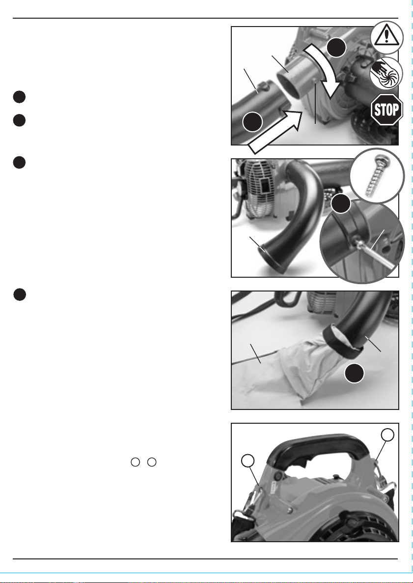
Slide the vacuum nozzle over the vacuum
tube and locking lug.
Rotate the nozzle clockwise to lock in place.
Secure the vacuum nozzle in place using the
supplied M5
×
10 screw and the screwdriver
end of the box spanner .
Slide the vacuum tube over the air intake
port and locking lug .
Rotate the tube clockwise to lock in place.
Fig.5
Fig.6
Fig.7
2
4
3
5
6
2
3
4
5
6
8.2 ASSEMBLING THE VACUUM
TUBES – FIGS. 4 – 7
Warning! Stop the engine and put the switch to
STOP position before installing parts, making
adjustments, cleaning or when not in use. Failure to
do so could result in possible serious injury.
Unscrew the retaining knob on the vacuum
intake cover .
1
Fig.4
1
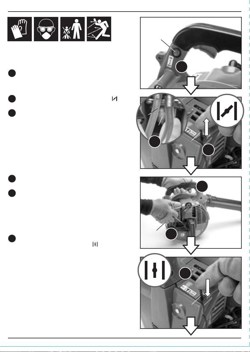
9.2 COLD STARTING THE ENGINE –
FIGS. 16 – 20
Rest the blower/vac on a stable surface.
Press the ON/OFF/IGNITION switch to the
‘I’ (ON) position.
Standing behind the machine, firmly grip the
front handle with your hand.
With your other hand grip the recoil starter cord
. Pull the starter cord using short sharp
movements.
Note: Do not use the full length of the recoil starter
cord as this can cause breakage or premature
failure. Do not release the starter cord to recoil on
its own. Damage will occur to the mechanism.
Once the engine tries to fire, push the choke
lever downwards to the the (open)
position.
Note: If there is a strong smell of fuel this indicates
that the engine may be flooded. Wait a few minutes
before attempting to restart the machine as if the
engine were warm i.e. no choke.
Pull the choke lever upwards to the
(closed) position.
Pump the primer eight times until fuel flows
in and out of the discharge line with no air
bubbles.
1
2
3
4
5
6
Fig.16
Fig.19
Fig.17
Fig.18
1
2
4
5
6
3
- 12 -
8. ASSEMBLING THE PETROL BLOWER/VAC8. ASSEMBLING THE PETROL BLOWER/VAC
Secure the collection bag intake tube in
place using the supplied M5
×
10 screw and
the screwdriver end of the box spanner .
- 13 -
3
Secure the collection bag to the collection
bag intake tube using the fastenings
attached at the opening of the bag.
4
The carry strap is attached by threading each of
the 2 sprung loaded buckles through the
holes in the 2 attachment points .
1
Fig.9
Fig.10
Fig.11
Fig.12
8.4 ATTACHING THE CARRYING
STRAP – FIGS. 11 – 12
The petrol motor unit has 2 fastening points for the
attachment of the carry strap ( & ).
3
4
1
A
AB
B
8.3 ATTACHING THE COLLECTION
BAG – FIGS. 8 – 10
Warning! Stop the engine and put the switch to
STOP position before installing parts, making
adjustments, cleaning or when not in use. Failure to
do so could result in possible serious injury.
Slide the collection bag intake tube over
the discharge port and locking lug .
Rotate the tube clockwise to lock in place.
Fig.8
1
2
1
2
9.1 FUELLING – FIGS. 13 – 15
This petrol blower vac is equipped with a 2 stroke
air cooled petrol engine.
This type of engine requires a mixture of fuel and oil
to perform and function. Failure to use the correct
oil, fuel or mixture ratio will cause permanent
damage to the engine. Only use fresh, clean, good
quality unleaded fuel mixed with a high quality 2
stroke oil. Do not use any other types of oil e.g.
engine oil as this will cause damage to the
engine.
For synthetic oil or semi-synthetic a mix ratio of 30:1
must be used. To mix a ratio of 30:1:
Add 166ml of 2 stroke oil into 5 litres of
unleaded fuel (2%).
Attention: Always handle fuel with caution.
Pour the fuel/oil mixture into a specifically
designed mixing receptacle before replacing
the cap and shaking gently.
Remove the fuel tank cap by turning it
anti-clockwise. To prevent identification
problems or accidents the fuel tank cap is
stamped with the symbol .
With the aid of a funnel, if needed, pour the
fuel/oil mixture into the fuel tank before
replacing the cap firmly. Avoid spillage and do
not over fill.
Note: Always mix and refuel in a well ventilated
area away from sources of ignition.
Note: Store fuel for short periods only and avoid
mixing more than is required. Store in a container
specifically designed for petrochemical applications
away from heat and direct sun light.
5L
166ml
Fig.13
Fig.14
Fig.15
1
2
3
4
3
4
1
30 : 1
2
- 11 -
9. OPERATING INSTRUCTIONS
- 14 -
8. ASSEMBLING THE PETROL BLOWER/VAC
Slide the vacuum nozzle over the vacuum
tube and locking lug.
Rotate the nozzle clockwise to lock in place.
Secure the vacuum nozzle in place using the
supplied M5
×
10 screw and the screwdriver
end of the box spanner .
Slide the vacuum tube over the air intake
port and locking lug .
Rotate the tube clockwise to lock in place.
Fig.5
Fig.6
Fig.7
2
4
3
5
6
2
3
4
5
6
8.2 ASSEMBLING THE VACUUM
TUBES – FIGS. 4 – 7
Warning! Stop the engine and put the switch to
STOP position before installing parts, making
adjustments, cleaning or when not in use. Failure to
do so could result in possible serious injury.
Unscrew the retaining knob on the vacuum
intake cover .
1
Fig.4
1
9.2 COLD STARTING THE ENGINE –
FIGS. 16 – 20
Rest the blower/vac on a stable surface.
Press the ON/OFF/IGNITION switch to the
‘I’ (ON) position.
Standing behind the machine, firmly grip the
front handle with your hand.
With your other hand grip the recoil starter cord
. Pull the starter cord using short sharp
movements.
Note: Do not use the full length of the recoil starter
cord as this can cause breakage or premature
failure. Do not release the starter cord to recoil on
its own. Damage will occur to the mechanism.
Once the engine tries to fire, push the choke
lever downwards to the the (open)
position.
Note: If there is a strong smell of fuel this indicates
that the engine may be flooded. Wait a few minutes
before attempting to restart the machine as if the
engine were warm i.e. no choke.
Pull the choke lever upwards to the
(closed) position.
Pump the primer eight times until fuel flows
in and out of the discharge line with no air
bubbles.
1
2
3
4
5
6
Fig.16
Fig.19
Fig.17
Fig.18
1
2
4
5
6
3
- 10 - - 15 -
8. ASSEMBLING THE PETROL BLOWER/VAC
8.1 ASSEMBLING THE BLOWER
TUBES – FIGS. 1 – 3
Warning! Stop the engine and put the switch to
STOP position before installing parts, making
adjustments, cleaning or when not in use. Failure to
do so could result in possible serious injury.
Slide the blower tube over the discharge
port and locking lug .
Rotate the tube clockwise to lock in place.
Secure the blower tube in place using the
supplied M5
×
10 screw and the
screwdriver end of the box spanner .
Slide the blower nozzle on to the blower
tube and locking lug
Rotate the nozzle clockwise to lock in place.
1
2
3
4
5
Fig.1
Fig.2
Fig.3
2
3
4
5
1
Important: This petrol blower vac can switch from blowing to suction functions. This is achieved
by connecting the tubes to the correct mounting.
– For blowing function, the tube is fitted to the front outlet (see section 8.1: assembling the
blower tubes).
– For vacuum function, the collection bag is fitted to the front outlet and the main tube is fitted to
the mounting that is accessed by opening the vented side cover (see section 8.2: assembling
the vacuum tubes).
Once the motor has started, allow the motor to
warm up for a few minutes before commencing
operation.
7
9. OPERATING INSTRUCTIONS
Standing behind the machine, firmly grip the
front handle with your hand.
With your other hand grip the recoil starter cord
. Pull the starter cord using short sharp
movements.
– If the engine does not start, refer to the steps
highlighted in the previous section: 9.2 Cold
Starting the Engine.
4
5
Fig.20
2 – 3 mins
5 sec
7
9.3 WARM STARTING THE ENGINE –
FIGS. 21 – 23
Rest the blower/vac on a stable surface.
Press the ON/OFF/IGNITION switch to the
‘I’ (ON) position.
1
Fig.21
1
Push the choke lever downwards to the
(open) position.
Pump the primer eight times until fuel flows
in and out of the discharge line with no air
bubbles.
2
3
Fig.22
2
3
Fig.23
4
5

- 16 - - 9 -
9.4 STOPPING THE ENGINE – FIG. 24
To stop the engine, move the stop switch to
the “stop” position.
Note: If the blower/vac has been running at full
speed for a prolonged period allow the engine to
idle for a few minutes before stopping.
The engine must be stopped while carrying out any
other operation such as:
– Refuelling.
– Making checks or adjustments.
– Cleaning.
9.5 ADJUSTING THE ENGINE IDLE
SPEED – FIGS. 25 – 26
Start the engine by following the steps highlighted in
the previous section: 9.2 Cold Starting the Engine.
Run the engine at idle speed until operating
temperature is reached (2 – 3 minutes).
Use the supplied screwdriver to adjust the
engine idle speed to 2300 – 2500r/min.
Turn the idle screw clockwise to increase
engine idle speed. Turn the idle screw
counterclockwise to decrease engine idle
speed.
Warning! Machine tubes and intake cover must be
installed while adjusting engine idle! Engine idle
speed will also be affected if either the intake cover
or machine tubes are blocked, damaged or
incorrectly installed.
1
1
2
3
2
9. OPERATING INSTRUCTIONS
1
Fig.24
Fig.26
Fig.25
2 – 3 mins
2300 –
2500r/min
2 – 3 mins
2
2
3
7. UNPACKING AND CHECKING
7.1 PACKAGING
Carefully remove the machine from the packaging and examine it for any sign of damage that may
have happened during shipping. Lay the contents out and check them against the parts shown
below. If any part is damaged or missing; please contact the Draper Helpline (the telephone
number appears on the Title page) and do not attempt to use the machine.
The packaging material should be retained at least during the guarantee period: in case the
machine needs to be returned for repair.
Warning! Some of the packaging materials used may be harmful to children. Do not leave any of
these materials in the reach of children.
If any of the packaging is to be thrown away, make sure they are disposed of correctly; according
to local regulations.
7.2 WHAT´S IN THE BOX?
As well as the blower vac, there are several parts not fitted or attached to it.
Petrol motor unit.
Blower nozzle.
Blower tube.
Carry strap.
Collection bag
intake tube.
Vacuum tube.
Vacuum nozzle.
Collection bag.
Fuel mixing bottle.
Screwdriver.
Large hex. key.
Small hex. key.
Box spanner.
M5
×
10 Screw
×
3.
- 8 - - 17 -
6. TECHNICAL DESCRIPTION
6.1 IDENTIFICATION
Petrol motor unit.
Carry handle.
Throttle trigger.
ON/OFF/Ignition switch.
Blower nozzle.
Blower tube.
Vacuum air intake.
Carry strap.
Choke lever.
Recoil starter cord.
Air filter cover.
Fuel tank cap.
Fuel tank.
Side handle.
Exhaust.
Spark plug cap.
Fuel primer bulb.
Fig.28
9. OPERATING INSTRUCTIONS
9.6 USING THE BLOWER/VAC – FIGS. 27 – 29
Note: As a general rule, try to operate the machine using the lowest throttle setting necessary for
the task in hand.
Blower Operation – Figs. 27 – 28
Note: To set up the machine for blowing
applications, refer to Section 8: Assembling The
Petrol Blower/Vac.
– Use low throttle settings when clearing
lightweight materials from around lawns or
shrubbery.
– Use medium to higher throttle settings to move
lightweight grass or leaves from open areas.
– Use full throttle when moving heavy loads such
as dirt or snow.
– Machine noise increases at higher throttle
settings. Always use the lowest possible throttle
setting.
– To keep from scattering debris, blow around the
outer edges of a debris pile.
Never blow directly into the centre of a pile.
– Use rakes and brooms to loosen debris before
blowing.
– In dusty conditions, slightly dampen surface with
water (if available).
Vacuum Operation – Fig.29
Note: To set up the machine for vacuuming
applications, refer to Section 8: Assembling The
Petrol Blower/Vac.
– When using the machine in vacuuming
operation, be sure not to allow the collection
bag to become overfilled.
– Allowing the collection bag to become overfilled
will reduce the appliances effectiveness and
may cause damage to the bag itself or the
appliance.
Fig.27
Fig.29
1
2
1
2
5. HEALTH AND SAFETY INFORMATION
Regular maintenance tasks must be carried out at
specific intervals to retain the engine's performance.
10.1 CLEANING THE AIR FILTER –
FIGS. 30 – 32
A dirty, clogged air filter will restrict the air flow in to
the engine and will cause rough running. It will
increase fuel consumption and may result in starting
problems.
Attention: Stop the engine before removing the air
filter assembly.
Pull the choke lever upwards to the closed
position to prevent any debris entering the
carburettor inlet.
Unscrew the retaining bolt on the air filter
cover to remove it.
Remove the air filter element .
Wash the element in warm soapy water to clean
it. Do not use solvents to clean it.
Allow the filter to dry 100% before refitting it on
to the engine.
– Refit cover .
– Replace the filter if it appears worn or
damaged.
10.2 SPARK PLUG MAINTENANCE –
FIGS. 33 – 34
Over time the spark plug
can become
contaminated.
This can be due to adverse running
conditions such as, working with part throttle for a
prolonged period or a fuel mix containing too much
oil. This contamination can build up causing the
engine to run roughly, reduce the fuel consumption
or create starting problems.
Without using any tools so as to avoid damaging
the H.T. lead, remove the lead from the
back of the spark plug.
Fig.30
Fig.31
2
3
Fig.32
Fig.33
1
1
2
3
4
5
1
1
5
4
– Storing fuels in closed containers. Keeping in mind that fuels may evaporate at room
temperature and collect on the floor of closed rooms (risk of explosion).
– Start the device at least nine metres away from any stored fuels or flammable liquids.
Fuels are toxic, they contain substances that have an immediate toxic effect and may cause
permanent damage to your health. Take all precautionary measures to prevent your body from
absorbing any of these substances:
– Tank and siphon fuels only outdoors or in well-ventilated rooms.
– Do not inhale fuel fumes.
– Avoid contact with eyes and skin.
– Wear gloves when transferring fuel.
– When fuel has come into contact with your clothes, change them immediately. Clean your
clothes before putting them back on.
– Store fuels out of the reach of children.
When handled inappropriately, fuels may cause damage to the environment:
– Transfer fuel carefully. Fuel must never trickle into the ground or the sewage system.
– Dispose of any remaining fuel in an appropriate manner. Never dispose of fuel with regular
household waste.
– Fuels may be stored only for a limited time. Purchase only such quantities that can be used up
within a few months.
- 7 -
10. MAINTENANCE AND TROUBLESHOOTING
- 18 -

5. HEALTH AND SAFETY INFORMATION
5.1 SPECIFIC SAFETY INSTRUCTIONS FOR PETROL BLOWER/VAC’S
Warning! For your safety, please read and understand these instructions before assembling,
operating or maintaining this machine.
– Never attempt to modify or operate a modified machine. Fully assemble this machine,
including all relevant guards, before operating.
– Do not operate this machine without being completely familiar with the safety features and how
to operate them.
– Never operate this machine if the stop switch is faulty or not functioning.
– Never operate this machine while tired, ill or under the influence of drugs.
Danger! Keep out of the reach of children.
– Fully read and understand before attempting to assemble, operate or maintain the machine.
– Never allow people unfamiliar with these instructions to operate this machine. Local
regulations may restrict the age of the operator.
– Prior to each use, inspect the machine for signs of damage. Make sure the safety features are
present and functioning and that all visible nuts, bolts and screws remain tight. Vibration from
normal use can cause them to loosen over time.
– Never operate this machine with defective or missing guards.
Warning! Use of this product can pose a danger to wildlife. Before attempting to use this machine,
check the area, particularly long grass and under bushes for signs of life: if necessary relocate.
Note: Not all animals will be deterred by the noise of the product alone.
– Do not point the blower/vac nozzle in the direction of people or pets.
– Check the attachment is correctly fitted to the machine before attempting to start the engine.
Caution! As the user you are responsible for any injury to people or damage to property.
Warning! During use the engine gets very hot. Do not touch it, especially the exhaust.
– Always be aware of your surroundings, staying alert for possible hazards that you may not
hear over the noise of the engine.
– Always hold the blower/vac in your right hand, refer to the operating instructions in the manual.
– To reduce the risk of hearing loss associated with sound level, hearing protection is required.
– Wear suitable gloves to help reduce vibration fatigue.
Service
Have your power tool serviced by a qualified repair person using only identical replacement parts.
This will ensure that the safety of the power tool is maintained.
5.2 HEALTH AND SAFETY INFORMATION CONCERNING THE
USE OF FUELS
Fuels are inflammable and explosive. Reduce the risk of explosion and fire by:
– Turning off and cooling the motor down before filling the tank with fuel.
– Refraining from smoking and starting open fires when handling fuels.
– Storing and mixing fuels in approved and correspondingly labelled canisters.
10. MAINTENANCE AND TROUBLESHOOTING
10.3 CLEANING THE FUEL FILTER
The fuel tank is fitted with a filter.
– The filter is situated at the free end of the fuel pipe and can be picked out through the fuel port
with a piece of hooked wire.
– Check the fuel filter periodically. Do not allow dust to enter the fuel tank. Clogged filter will
cause difficulty when starting engine or abnormalities in engine performance.
Replace the filter if dirty.
When the inside of the fuel tank is dirty it can be cleaned by rinsing the tank out with petrol.
- 6 - - 19 -
Using the spark plug box spanner supplied
, turn the spark plug anticlockwise to
remove it.
Clean the spark plug and check the electrode
gap. Maintain a gap of 0.6 to 0.7mm.
– If required, replace the spark plug with a L7T
coded plug, or equivalent, gapped to 0.6 –
0.7mm.
Warning! Make sure you correctly seat the spark
plug thread in to the engine before screwing it
clockwise in to the head.
Fig.34
2
3
0.6mm to
0.7mm
2
3
10.4 TROUBLESHOOTING GUIDE
Fault Possible cause Remedy
Engine does not start.
Machine runs but
stutters.
1. No fuel in the tank.
2. The STOP/START switch
is in the STOP position.
3. Ignition cable plug not
firmly attached.
4. Ignition cable plug dirty.
5. Is there fuel inside the
combustion chamber.
6. The spark plug is dirty.
7. The distance between
the electrodes of the
spark plug is too large.
8. Wrong fuel.
9. Spark plug defective.
1. Is the choke set to the off
(closed) position.
1. Refuel tank.
2. Put the switch in the START
position.
3. Push the plug on tightly.
4. Clean the plug.
5. Remove the spark plug, dry off the
electrode and start at full throttle.
6. Clean the spark section.
7. Set the gap to 0.6 to 0.7mm.
8. Drain the tank and fill it with the
correct fuel.
9. Replace the spark plug.
1. Set the choke to the on (open)
position.

4. INTRODUCTION
4.1 SCOPE
This product is designed for blowing fallen leaves and other loose green matter prior to collection.
This product is designed for use in the domestic environment only.
4.2 SPECIFICATION
Stock No: ................................................................................................................................. 32301
Part No: .................................................................................................................................. BVP26
Engine displacement ............................................................................................................... 25.4cc
Maximum revolutions per min. (no load) ........................................................................... 7,000min-1
Maximum revolutions per min. at idle (no load)................................................................. 3,200min-1
Fuel tank capacity ..................................................................................................................... 0.65L
Fuel mixture...............................................................................................................................30:1††
Carburettor ................................................................................... Diaphragm type with primer pump
Spark plug .................................................................................................................................... L7T
Air flow:
Maximum air speed (blowing) ............................................................................. 75m/s (270km/h)
Maximum air speed (vacuuming)................................................................................... 6.3m3/min
Sound pressure level.............................................................................................................86dB(A)
Sound power level...............................................................................................................103dB(A)
Single value noise level (LWA)†...........................................................................................103dB(A)
Vibration level ................................................................................................................. 5.5±1.5m/s2
Dimensions (assembled) (L
×
W
×
H) ................................................................1210
×
520
×
360mm
Weight (dry, with vacuum tubes) ............................................................................................... 5.4kg
†A-weighted sound pressure level in accordance to 2000/14/EC.
††Use semi-synthetic 2 stroke oil.
4.3 HANDLING AND STORAGE
Care must still be taken when handling and lifting. Dropping this machine will have an effect on the
accuracy and may also result in personal injury. This machine is not a toy and must be respected.
The environment will have a negative result on its operation if you are not careful. If the air is
damp, components will rust. If the machine is unprotected from dust and debris; components will
become clogged: And if not cleaned and maintained correctly or regularly the machine will not
perform at its best.
- 5 -- 20 -
10. MAINTENANCE AND TROUBLESHOOTING
10.4 TROUBLESHOOTING GUIDE (continued)
10.5 CLEANING AND MAINTENANCE OVERVIEW
Fault Possible cause Remedy
The motor does not
reach its maximum
speed.
Important: Please note, all repairs/servicing should be carried out by a qualified person.
1. The air filter is dirty.
2. The spark plug is dirty.
3. The distance between
the electrodes of the
spark plug is too large.
4. Wrong fuel.
1. Clean the air filter.
2. Clean the spark plug.
3. Set the gap to 0.6 to 0.7mm.
4. Drain the tank and fill with the
correct fuel.
Prior to every start.
Every 10 operating hours (more frequently in dusty conditions).
Every 10/15 operating hours.
Every 50 operating hours. (more frequently for reduced engine performance).
1. Check/clean/replace air filter element.
2. Check the pull starter for damage to the
starter .
3. Checking threaded connections for
tightness.
4. Remove dirt and debris from the
machine’s exterior
5. Inspect engine cooling fins for
accumulations of dirt and debris, clean as
necessary.
1. Check/clean/replace air filter element.
1. See section 10.1.
2. Visual inspection/testing.
3. Visual inspection/testing.
4. Visual inspection.
5. Visual inspection.
1. Check/clean/replace spark plug. 1. See section 10.2.
1. Inspect the entire machine and tubes for
damage, including loose or missing
components and repair as necessary.
2. Replace spark plug.
3. Inspect/replace fuel filter.
1. Visual inspection.
2. See section 10.2.
3. See section 10.3.
1. See section 10.1.
10.6 STORING THE MACHINE FOR AN EXTENDED PERIOD OF TIME
(3 MONTHS OR LONGER)
Before an extended period of disuse, you must remove the fuel from the machine.
– Drain the fuel tank, then start the engine and let it run until it stops of its own accord.
This manual suits for next models
1
Table of contents
Other Draper Blower manuals

Draper
Draper BV2201A User manual

Draper
Draper BP30A User manual

Draper
Draper BV2000 User manual

Draper
Draper BP25A User manual

Draper
Draper 70526 User manual

Draper
Draper BV3000 User manual

Draper
Draper 230V 2200W Garden Blower/Vacuum User manual

Draper
Draper BV3000 User manual

Draper
Draper BP25 User manual

Draper
Draper BP33 User manual


