Drawmer DL221 User manual

DRAWMER
Dual Channel
Vacuum Tube Compressor
OPERATOR’S MANUAL
CONTENTS
Warranty
Safety Consideration
Chapter 1 - Introduction
Introduction
Installation
AudioConnections
PowerConnection
Chapter 2 - Control Description
ControlDescription
TheQuickSetupProcedure
Chapter 3 - General Information
Ifafaultdevelops
Contacting Drawmer
Block Diagram
. . . . . . . . . . . . . . . . . . . . . . . . . . . . . . . . . . . . . . . . . . . . . . . . . . . . . . . . . . . 2
. . . . . . . . . . . . . . . . . . . . . . . . . . . . . . . . . . . . . . . . . . . . . . . . 2
. . . . . . . . . . . . . . . . . . . . . . . . . . . . . . . . . . . . . . . . . . . . . . . . . . . . . . . 3
. . . . . . . . . . . . . . . . . . . . . . . . . . . . . . . . . . . . . . . . . . . . . . . . . . . . . . . . 4
. . . . . . . . . . . . . . . . . . . . . . . . . . . . . . . . . . . . . . . . . . . . . . . . . 4
. . . . . . . . . . . . . . . . . . . . . . . . . . . . . . . . . . . . . . . . . . . . . . . . . 5
. . . . . . . . . . . . . . . . . . . . . . . . . . . . . . . . . . . . . . . . . . . . . . . . . 6
. . . . . . . . . . . . . . . . . . . . . . . . . . . . . . . . . . . . . . . . . 7
. . . . . . . . . . . . . . . . . . . . . . . . . . . . . . . . . . . . . . . . . . . . . . . . . . . 8
. . . . . . . . . . . . . . . . . . . . . . . . . . . . . . . . . . . . . . . . . . . . . . . . 8
. . . . . . . . . . . . . . . . . . . . . . . . . . . . . . . . . . . . . . . . . . . . . . . . . . . . 9

2DRAWMER 1968 OPERATOR’SMANUAL
Drawmer Electronics Ltd., warrants the Drawmer 1968 Dual
Channel Vacuum Tube Compressor to conform substantially
to the specifications of this manual for a period of one year
from the original date of purchase when used in accordance
withthespecificationsdetailedinthismanual.Inthecaseofa
valid warranty claim, your sole and exclusive remedy and
Drawmer’sentireliabilityunder any theory of liabilitywill be to,
atDrawmer’s discretion, repairor replacetheproductwithout
charge,or,ifnotpossible,torefundthepurchasepricetoyou.
Thiswarranty is nottransferable.It applies only totheoriginal
purchaser of the product.
For warranty service please call your local Drawmer dealer.
Alternatively call Drawmer Electronics Ltd. at +44 (0)1709
527574. Then ship the defective product, with transportation
andinsurance charges pre-paid, to DrawmerElectronics Ltd.,
ColemanStreet,Parkgate,Rotherham,S626ELUK.Write the
RA number in large letters in a prominent position on the
shippingbox.Encloseyourname,address,telephonenumber,
copyoftheoriginalsalesinvoiceandadetaileddescriptionof
theproblem.Drawmerwillnotacceptresponsibilityforlossor
damage during transit.
This warranty is void if the product has been damaged by
misuse, modification or unauthorised repair.
THIS WARRANTY IS IN LIEU OF ALL WARRANTIES,
WHETHERORALOR WRITTEN,EXPRESSED,IMPLIEDOR
STATUTORY.DRAWMER MAKES NO OTHER WARRANTY
EITHER EXPRESS OR IMPLIED, INCLUDING, WITHOUT
LIMITATION, ANY IMPLIED WARRANTIES OF
MERCHANTABILITY,FITNESSFORAPARTICULARPURPOSE,
OR NON-INFRINGEMENT. PURCHASER’S SOLE AND
EXCLUSIVEREMEDYUNDERTHISWARRANTYSHALLBE
REPAIRORREPLACEMENTASSPECIFIEDHEREIN.
IN NO EVENT WILL DRAWMER ELECTRONICS LTD. BE
LIABLEFORANY DIRECT,INDIRECT,SPECIAL,INCIDENTAL
ORCONSEQUENTIAL DAMAGES RESULTING FROM ANY
DEFECT IN THE PRODUCT, INCLUDING LOST PROFITS,
DAMAGETOPROPERTY,AND,TOTHEEXTENTPERMITTED
BY LAW, DAMAGE FOR PERSONAL INJURY, EVEN IF
DRAWMERHAS BEEN ADVISED OF THEPOSSIBILITY OF
SUCHDAMAGES.
Somestatesandspecific countries do not allowtheexclusion
of implied warranties or limitations on how long an implied
warranty may last, so the above limitations may not apply to
you. This warranty gives you specific legal rights. You may
haveadditionalrightsthatvaryfrom state to state, andcountry
tocountry.
In the interests of product development, Drawmer reserve the right to modify or
improve specifications of this product at any time, without prior notice.
ONE YEAR LIMITED WARRANTY
COPYRIGHT
This manual is copyrighted c 2004 by Drawmer Electronics Ltd. With all rights reserved. Under copyright
laws, no part of this publication may be reproduced, transmitted, stored in a retrieval system or translated
intoany language in any form by any means, mechanical, optical, electronic, recording, or otherwise, with-
out the written permission of Drawmer Electronics Ltd.
DRAWMER
1968
DualChannel
Vacuum Tube Compressor
SAFETY CONSIDERATIONS
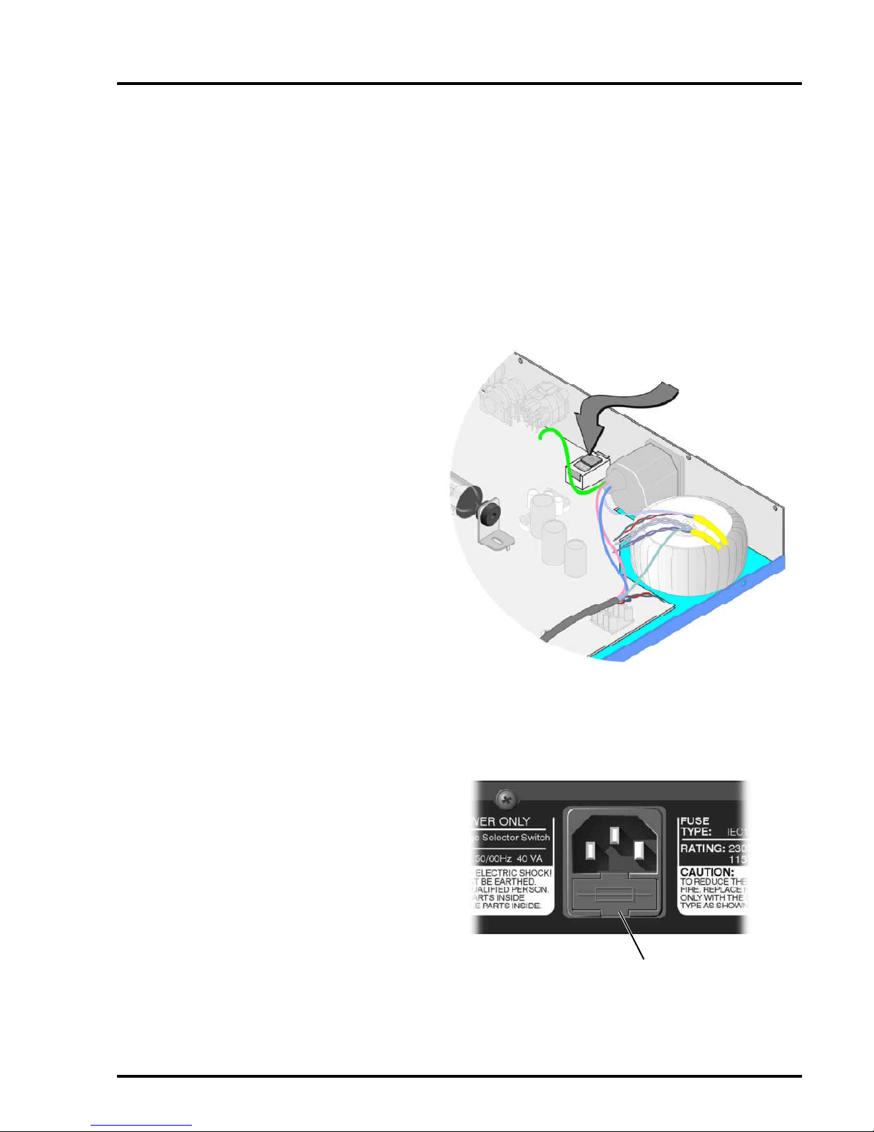
CAUTION-MAINSFUSE
TO REDUCE THE RISK OF FIRE
REPLACETHE MAINS FUSE ONLY WITH
A FUSE THAT CONFORMS TO IEC127-2.
250VOLTWORKING, TIME DELAYTYPE
AND BODY SIZE OF 20mm x 5mm.
THEMAINS INPUT FUSE MUST BE
RATEDAT230V=T160mA and115V=T315mA.
CAUTION-MAINSCABLE
DO NOT ATTEMPT TO CHANGE
OR TAMPER WITH THE
SUPPLIEDMAINSCABLE.
CAUTION-SERVICING
DO NOT PERFORM ANY SERVICING.
REFERALL SERVICINGTO QUALIFIED
SERVICE PERSONNEL.
WARNING
TO REDUCE THE RISK OF FIRE OR
ELECTRIC SHOCK DO NOT EXPOSE
THISEQUIPMENT TO RAIN OR MOISTURE.

3
DRAWMER 1968 OPERATOR’SMANUAL
DRAWMER
1968 Mercenary Edition
DUAL CHANNEL VACUUM TUBE COMPRESSOR
The 1968 is a 1U Tube/FET dual channel / ‘stereo bus’
compressorwhich by designdeliversa transparent ‘open’
soundeven during periods of heavy compression.
The original Drawmer 1960 used a tube stage at the front
ofthe compressor, whilst the 1968 utilisies a J-FET (Field
EffectTransistor)gainreductioncircuit thatoperates faster
thananopto-isolator. The compressor uses a 12AX7 tube
makeupgain amplifier where you can add, with the Output
Gain control, up to 20 dB of additional gain.
The need for a ratio control as been removed as the
compressoroperates on the soft knee principle where the
onset of compression is progressive.
The 1968 expands attack times to six choices: 2, 9, 15,
25, 30 and 50 ms. Release times come in three fixed
times (100ms, 500 ms and 1 second) and three program-
dependent choices--200 ms to 2 sec, 500 ms to 5 sec
and 1 to 10 seconds--all program-dependent and
automatic.
The1968 providesfull sidechainaccess forconnectingan
CHAPTER 1
INTRODUCTION
external equalizer for vocal stressing or de-essing.
Featured on both channels is a switchable ‘BIG’ mode
which applies less processing to the fundamental low
frequency but still disciplines the upward associated
harmonics which if untamed can result in a ‘boomy’ or
‘boxy’sound.The result- asolidbottom endwith enhanced
sub-bass and a smoother, wider frequency response
overall. This lets the operator use more compression on
an overall mix with less pumping action caused by a kick
and/or bass instrument.
The outputs of Channels 1 and 2 are monitored on two
yellow illuminated VU meters - with a red warning glow to
signify ‘approaching clipping’. A three-position switch
adjuststhe meters toshow either normal outputlevel, gain
reduction or VU +10dB mode, which re-scales the meter
for users working at ‘hot’ output levels.
Anoutput switch selects normal compressor output, hard-
wired bypass and sidechain listen.
The key features are as follows:
• 2Channel Tube/FET Compressor
• 2 soft-knee compressors with variable threshold, attack, release and output gain
• Switchable BIG control on each channel
• Dual mono or true stereo link operation
• Side chain access and side chain listen facility
• VUmeteringofgainreductionandoutputlevels
• Switchable +10dB mode on VU re-scales the meter for users working at ‘hot’ output levels.
• VU red warning glow to signify ‘approaching clipping’
• Balanced +4dB XLR in/outs

4DRAWMER 1968 OPERATOR’SMANUAL
The1968 is designed for standard 19" rack mounting and
occupies1Uofrackspace.Avoidmountingtheunit directly
above power amplifiers or power supplies that radiate
significantamounts of heat and always connect the mains
earth to the unit. Fibre or plastic washers may be
used to prevent the front panel becoming marked by the
mountingbolts. Becausethe tube circuitrygenerates more
heat than an equivalent solid-state design, it is advisable
toleave spaceabove the unitto allow theheat to dissipate.
INSTALLATION
AUDIO CONNECTIONS
Theinputs and outputs are electronically balanced on conventionally wiredXLRs(pin 1 screen, pin 2 hot, pin 3 cold and
XLR shell is connected to chassis). The operating level is nominally +4dBu. Balanced use is recommended.
• Interference:
If the unit is to be used where it maybe exposed to
highlevels ofdisturbance suchas found closeto aTV
or radio transmitter, we advise that the unit is oper-
ated in a balanced configuration. The screens of the
signalcablesshould be connected to the chassis con-
nectiononthe XLR connector as opposed to connect-
ing to pin1. The 1968 conforms to the EMC stand-
ards.
• Ground Loops:
If ground loop problems are encountered, never dis-
connect the mains earth, but instead, try disconnect-
ing the signal screen on one end of each of the cables
connecting the outputs of the 1968 to the patchbay. If
such measures are necessary, balanced operation is
recommended.
fig.1 1968 WIRING
The side chain feature on the 1968 is part of the compressor feedback stage and would normally be connected to a
normalised or semi-normalised pair of patchbay contacts. This would allow the user to insert additional EQ for some
de-essing, or frequency conscious compression. The side-chain access point is unbalanced, connection is via stereo
3" jacks, the wiring convention being: ring is signal send, tip is signal return and sleeve ground.

5
DRAWMER 1968 OPERATOR’SMANUAL
The1968 unit will besupplied with a power cablesuitable for domestic poweroutletsin your country. Foryour own safety,
it is important that you use this cable to connect to the mains supply earth. The cable must not be tampered with or
modified.
The power supply socket has an integral fuse drawer containing the power fuse of the same value, to suit the mains
voltageforwhichthe unit has been supplied. Removal of the drawer is only possible with the power cord removed. The
fuseshould never blow undernormal operation. If the fuseis suspected of havingblown, thena fault will haveoccurred
andthis faultcondition should beinspected by aqualified serviceengineer. When replacingthe fuse, alwayscomply with
the Safety Instructions.
If the unit is to be used with a mains input operating voltage different to that for which the unit is supplied, the following
procedure must be carried out by a technically competent person,(see following diagrams)
POWER CONNECTION
1: Disconnect the unit from the mains.
2: Using a number 1 size pozidrive screwdriver,
removethesevenself-tapping screwsthatretainthe
topcover.Twoscrews arefoundalong eachside;two
alongthe top edge atthe rear; and theupper central
screwon the front facia panel.
3: Slide the voltage change-over switch(SW8) until
thecorrect(or nearest)mains inputvoltage isvisible
on the switch actuator.
(see fig.2)
For conversion to 115Volt AC (previously set to
230Volt AC).....
4a: Exchange the 160mA fuse below the mains
socket for a similar type rated at 315mA
For conversion to 230Volt AC (previously set to
115Volt AC).....
4b: Exchange the 315mA fuse below the mains
socket for a similar type rated at 160mA
In both cases:
5: Replace the top cover using the seven screws.
6: Re-connect to mains power source.
Fuse
fig.2 The Voltage Selector Switch
fig.3 The Location of the Fuse

6DRAWMER 1968 OPERATOR’SMANUAL
CONTROL DESCRIPTION
Threshold: Determinesthe inputlevel abovewhich gain reductionwill beapplied andmay be
set in the range -30dB to infinity. Because the compression system is based on
the Soft Knee principle, the onset of compression is progressive, so no Ratio
control is necessary.
Big: Makes the compressor side chain less sensitive to low bass frequencies, so
reducingthe ducking effect caused by bass energy andeffectively boosting the
bass output.
Attack: Sixswitchable Attack settings are provided giving various settings. The actual
attacktime is further modified by the release setting chosen
Attack Times: 12 ms
28 msec
315 msec
425 msec
530 msec
650 msec
Release: There are threefixed Release times and a further three which areprogramme
dependent.Switch settings 1 through to 3 provide progressively increasing
release times, while positions 4, 5 and 6 cause the release times to vary in a
manner which automatically adapts to the dynamics of the incoming signal, as
detailed below.
Release Times 1100 ms (Fixed)
2500 msec (Fixed)
31 sec (Fixed)
4Semi-Auto 200 ms to 2 sec Signal dependent
5Semi-Auto 500 ms to 5 sec signal dependent
6Automatic 1 sec to 10 sec signal dependent
CHAPTER 2

7
DRAWMER 1968 OPERATOR’SMANUAL
Initially, set the Attack selector to 3 (a Medium position) and set Release to
6 (Programme Dependent).
Set the Mode switch to Normal and the Meter switch to GR.
Withprogrammematerialplaying,adjust theThresholdcontroluntil thedesired
amount of gain reduction registers on the meters.
Use the Output Gain control to restore any level lost due to compression.
If necessary, change the Attack and Release settings to suit the material.
THE QUICK SETUP PROCEDURE
Use the following procedure to setup the compressor.
Output:(Gain) The Output level may be amplified, or attenuated by up to 20dB to compensate
for level changes caused by compression.
VU Meter A moving coil VU meter monitors either the level of the output signal or the
amountofgain reductiontakingplace.Becausethe meterhasVUcharacteristics,
it closely reflects what is actually being heard, though will not respond quickly
enough to register short signal peaks.
VU +10dB/VU / GR A three-position switch adjusts the meters to show either normal output level,
gainreduction or VU +10dB mode, which re-scales the meterforusers working
at‘hot’ output levels. In other words, with the switch at VU +10dB - when the VU
meter reads 0dB the actual level is +10dB.
Side Chain/Norm/Bypass S/CListen routesthe side-chain signal directlyto the outputallowingthe effects
ofany additional side-chain processing, such as equalisation, to be monitored.
Normal mode, the signal is passed through the compressor.
Bypass takes the compressor and the vacuum tubes out of circuit path; the
output signal is taken from the channel input point.
Stereo Link This makes Channel 1 controls the stereo master and disables the compressor
stage of channel 2 when the unit is used for processing a stereo signal. Since
thesame gain reduction is applied toboth audio channels no image shifting can
occur.
•
•
•
•
•

8DRAWMER 1968 OPERATOR’SMANUAL
IF A FAULT DEVELOPS
For warranty service please call Drawmer Electronics Ltd. or
their nearest authorised service facility, giving full details of
the difficulty.
A list of all main dealers can be found on the Drawmer
webpages.
On receipt of this information, service or shipping instructions
will be forwarded to you.
No equipment should be returned under the warranty without
prior consent from Drawmer or their authorised representative.
For service claims under the warranty agreement a service
Returns Authorisation (RA) number will be issued.
Write this RA number in large letters in a prominent position
on the shipping box. Enclose your name, address, telephone
number, copy of the original sales invoice and a detailed
description of the problem.
Authorised returns should be prepaid and must be insured.
All Drawmer products are packaged in specially designed
containers for protection. If the unit is to be returned, the original
container must be used. If this container is not available, then
the equipment should be packaged in substantial shock-proof
material, capable of withstanding the handling for the transit.
CONTACTING DRAWMER
Drawmer Electronics Ltd., will be pleased to answer all
application questions to enhance your usage of this
equipment. Please address correspondence to:
Drawmer (Technical Help line)
Coleman Street
Parkgate
Rotherham
S62 6EL
UK
Alternatively contact us by E-mail on :
Further information on all Drawmer dealers, Authorised service
departments and other contact information can be obtained
from our web pages on:
http://www.drawmer.com
GENERAL INFORMATION
CHAPTER 3
It is the responsibility of the installer to ensure that the continuous power rating of the speakers is not exceeded, as Drawmer
Electronics Ltd will not accept any responsibitlity for speaker damage caused by incorrect settings.

9
DRAWMER 1968 OPERATOR’SMANUAL
BLOCKDIAGRAM
1968 ver 01 A 05/05/04
Other manuals for DL221
1
Table of contents
Other Drawmer Recording Equipment manuals

Drawmer
Drawmer 1978 User manual

Drawmer
Drawmer S2 User manual

Drawmer
Drawmer DS201 User manual

Drawmer
Drawmer 1973 User manual

Drawmer
Drawmer S3 User manual

Drawmer
Drawmer TS2 User manual

Drawmer
Drawmer dl441 User manual

Drawmer
Drawmer DL221 User manual

Drawmer
Drawmer 1969 User manual

Drawmer
Drawmer DS501 User manual
Popular Recording Equipment manuals by other brands

Directed
Directed XPRESSKIT XKLOADER2 installation guide

IntesisBox
IntesisBox PA-AW-MBS-1 installation instructions

Vicon
Vicon V1300X-IAF Instructions for installation and operation

Nav TV
Nav TV BMW-EVO ID6 Install manual

Bettermaker
Bettermaker C502V Operation manual

Toshiba
Toshiba BMS-IFBN1280U-E installation manual