Drawmer S2 User manual

DRAWMER
S2
Dual Channel
Vacuum Tube Compressor
OPERATOR’S MANUAL
CONTENTS
Warranty
Safety Consideration
Chapter 1 - Introduction
Introduction
Installation
Audio Connections
PowerConnection
Chapter 2 - Control Description
Control Description
Quick Setup Procedure
Chapter 3 - General Information
Ifafaultdevelops
ContactingDrawmer
Specification
Block Diagram
Session Recall Sheet
. . . . . . . . . . . . . . . . . . . . . . . . . . . . . . . . . . . . . . . . . . . . . . . . . . . . . . . . . . . 2
. . . . . . . . . . . . . . . . . . . . . . . . . . . . . . . . . . . . . . . . . . . . . . . . 2
. . . . . . . . . . . . . . . . . . . . . . . . . . . . . . . . . . . . . . . . . . . . . . . . . . . . . . . 3
. . . . . . . . . . . . . . . . . . . . . . . . . . . . . . . . . . . . . . . . . . . . . . . . . . . . . . . . 4
. . . . . . . . . . . . . . . . . . . . . . . . . . . . . . . . . . . . . . . . . . . . . . . . . 5
. . . . . . . . . . . . . . . . . . . . . . . . . . . . . . . . . . . . . . . . . . . . . . . . . 5
. . . . . . . . . . . . . . . . . . . . . . . . . . . . . . . . . . . . . . . . . . . . . . . . . 6
. . . . . . . . . . . . . . . . . . . . . . . . . . . . . . . . . . . . . . . . . . . . . 9
. . . . . . . . . . . . . . . . . . . . . . . . . . . . . . . . . . . . . . . . . . . . . . . . . 10
. . . . . . . . . . . . . . . . . . . . . . . . . . . . . . . . . . . . . . . . . . . . . . . .10
. . . . . . . . . . . . . . . . . . . . . . . . . . . . . . . . . . . . . . . . . . . . . . . . . . . . .10
. . . . . . . . . . . . . . . . . . . . . . . . . . . . . . . . . . . . . . . . . . . . . . . . . . . 11
. . . . . . . . . . . . . . . . . . . . . . . . . . . . . . . . . . . . . . . . . . . . . 13

2DRAWMER S2 OPERATOR’S MANUAL
DrawmerElectronicsLtd.,warrantstheDrawmerS2Dual
Channel Vacuum Tube Compressor to conform
substantiallytothespecificationsofthismanualforaperiod
of one year from the original date of purchase when used
in accordance with the specifications detailed in this
manual. In the case of a valid warranty claim, your sole
andexclusive remedy and Drawmer’s entire liabilityunder
any theory of liability will be to, at Drawmer’s discretion,
repair or replace the product without charge, or, if not
possible,torefundthe purchaseprice toyou.Thiswarranty
isnottransferable. It applies only to the original purchaser
of the product.
ForwarrantyservicepleasecallyourlocalDrawmerdealer.
AlternativelycallDrawmer Electronics Ltd. at +44 (0)1709
527574.Thenshipthedefectiveproduct,withtransportation
and insurance charges prepaid, to Drawmer Electronics
Ltd.,Coleman Street, Parkgate, Rotherham, S626ELUK.
Writethe RAnumber inlargeletters inaprominentposition
on the shipping box. Enclose your name, address,
telephonenumber,copyofthe original sales invoice anda
detaileddescriptionoftheproblem.Drawmerwillnotaccept
responsibility for loss or damage during transit.
This warranty is void if the product has been damaged by
misuse,modificationor unauthorised repair.
THIS WARRANTY IS IN LIEU OF ALL WARRANTIES,
WHETHERORALORWRITTEN,EXPRESSED,IMPLIED
OR STATUTORY. DRAWMER MAKES NO OTHER
WARRANTY EITHER EXPRESS OR IMPLIED,
INCLUDING, WITHOUT LIMITATION, ANY IMPLIED
WARRANTIES OF MERCHANTABILITY, FITNESS FOR
APARTICULAR PURPOSE, OR NON-INFRINGEMENT.
PURCHASER’S SOLE AND EXCLUSIVE REMEDY
UNDER THIS WARRANTY SHALL BE REPAIR OR
REPLACEMENTAS SPECIFIED HEREIN.
INNOEVENTWILLDRAWMERELECTRONICSLTD.BE
LIABLE FOR ANY DIRECT, INDIRECT, SPECIAL,
INCIDENTAL OR CONSEQUENTIAL DAMAGES
RESULTING FROM ANY DEFECT IN THE PRODUCT,
INCLUDINGLOSTPROFITS,DAMAGETOPROPERTY,
AND,TOTHE EXTENT PERMITTED BYLAW, DAMAGE
FOR PERSONAL INJURY, EVEN IF DRAWMER HAS
BEEN ADVISED OF THE POSSIBILITY OF SUCH
DAMAGES.
Some states and specific countries do not allow the
exclusion of implied warranties or limitations on how long
animplied warranty maylast,sothe above limitationsmay
not apply to you. This warranty gives you specific legal
rights.You may have additional rights that vary from state
to state, and country to country.
In the interests of product development, Drawmer reserve the right to modify or
improve specifications of this product at any time, without prior notice.
ONE YEAR LIMITED WARRANTY
COPYRIGHT
This manual is copyrighted © 2008 by Drawmer Electronics Ltd. With all rights reserved. Under copyright
laws, no part of this publication may be reproduced, transmitted, stored in a retrieval system or translated
into any language in any form by any means, mechanical, optical, electronic, recording, or otherwise, with-
out the written permission of Drawmer Electronics Ltd.
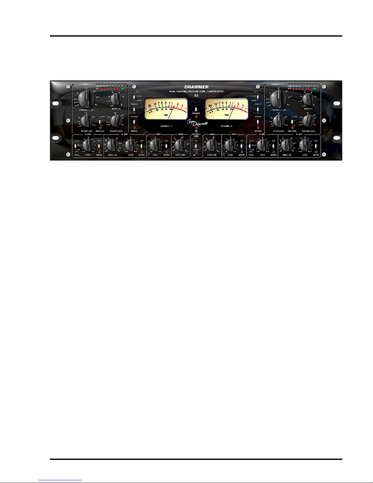
DRAWMER
S2
DualChannel
Vacuum Tube Compressor
SAFETY CONSIDERATIONS
CAUTION-MAINSFUSE
TO REDUCE THE RISK OF FIRE
REPLACE THE MAINS FUSE ONLY WITH
A FUSE THAT CONFORMS TO IEC127-2.
250 VOLT WORKING, TIME DELAY TYPE
AND BODY SIZE OF 20mm x 5mm.
THEMAINS INPUTFUSE MUSTBE
RATED AT 230V=T500mA and 115V=T1Amp.
CAUTION-MAINSCABLE
DO NOT ATTEMPT TO CHANGE
OR TAMPER WITH THE
SUPPLIEDMAINS CABLE.
CAUTION-SERVICING
DO NOT PERFORM ANY SERVICING.
REFER ALL SERVICING TO QUALIFIED
SERVICE PERSONNEL.
WARNING
TO REDUCE THE RISK OF FIRE OR
ELECTRIC SHOCK DO NOT EXPOSE
THIS EQUIPMENT TO RAIN OR MOISTURE.

3
DRAWMER S2 OPERATOR’S MANUAL
DRAWMER
S2
DUAL CHANNEL VACUUM TUBE COMPRESSOR
CHAPTER 1
INTRODUCTION
ThenewS2Signature Series Dual Channel Tube Compressor is the latest product to emerge from Ivor Drawmer’s high
enddesignsandoffers an ‘all tube - no technical compromise’ circuit using only thehighest grade components. The S2
features a host of new creative processing possibilities never before found in an all analogue dynamics package.
BIG- Retains bass frequencies and minimizes undesirable ‘pumping’ by rolling off the detection signal at 75, 125 or
250Hz (user switchable). A fully variable level control allows for the desired amount of Big processing and an in/out
switch provides the option to remove from the signal path for A/B comparison.
BRIGHT- A dynamic high frequency enhancer to keep compressed audio sounding fresh and bright with continuously
variablefrequency control (500Hz to 20kHz) and amountof dynamic enhancement.
DRY-Mixesuser defined amount of ‘uncompressed’ signal with the compressedsignal to create ‘parallelcompression
effect’ without the need for external mixing devices.
•2CHANNELSOFT-KNEE TUBE COMPRESSOR
•FULLYBALANCEDINTERNALSIGNALPATH
• CLASS A DESIGN
•ISOLATION TRANSFORMERSINANDOUT
•‘ALLTUBE’CIRCUITDESIGN
• VARIABLEATTACKAND RELEASE WITH OPTIONAL‘PROGRAMME
DEPENDENT’AUTO RELEASE OPERATION
•DUALMONO OR STEREO LINK OPERATION
• SWITCHABLE ‘PEAK’OR ‘VU’ METERING TO DISPLAYTRANSIENTS
• SWITCHABLE +10dB OR +20dB METER RE-SCALE MODES
•8 SEGMENT GAIN REDUCTIONMETERING
•‘VARIABLE-BIG’MODEFORRETAININGLOWFREQUENCIES
•‘VARIABLE-AIR’MODEFORENHANCINGHIGHFREQUENCIES
• ‘DRY’MIX MODE FOR ‘PARALLEL COMPRESSION EFFECT’
•BALANCED XLRINPUTS/OUTPUTS

4DRAWMER S2 OPERATOR’S MANUAL
The S2 is designed for standard 19" rack mounting and
occupies 3U of rack space. Fibre or plastic washers may
be used to prevent the front panel becoming marked by
the mounting bolts. Always connect the mains earth to
the unit.
Because the S2 contains six valves it will generate more
heat than a simple solid state unit. Avoid mounting the
unitdirectly above power amplifiers orpowersuppliesthat
radiatesignificant amounts ofheat.In addition itisadvised
that you leave at least 1U of space above to allow heat to
dissipate.Alternatively, a fan should be fitted somewhere
near to the rear of the unit to circulate cooler air and help
expel any excess heat. (see fig. 1)
INSTALLATION
fig.2 TYPICAL S2 SETUP
fig.1 RACK MOUNT POSITIONING

5
DRAWMER S2 OPERATOR’S MANUAL
The unit will have been supplied with a power cable
suitable for domestic power outlets in your country.
For your own safety it is important that you use this
cable. The unit should always be connected to the
mains supply earth using this cable, and no other.
If for some reason the unit is to be used at a mains
input operating voltage which is different to that as
supplied,the followingprocedure mustbecarried out.
1: Disconnect the unit from the mains.
2: Remove the two screws holding the voltage
selection cover-plate.
3: Remove the cover plate and slide the switch
fully to its opposite end.
4:Rotatethecoverplateonehalf turn(180degrees)
and refit the two screws.
5: Replace with a correctly rated fuse for the
selected operation voltage in the IEC socket:
230V-T500mA and 115V-T1Amp
6: Re-connect to mains power source.
Neverdisconnect the earth
fromthemainssupply
AUDIO CONNECTIONS
The inputs and outputs are electronically balanced on
conventionally wired XLRs (pin 1 screen, pin 2 hot, pin 3
cold and XLR shell is connected to chassis). The operating
level is nominally +4dBu. Balanced use is recommended.
•Interference:
IftheS2 is to be used where it maybe exposed to high
levels of disturbance such as found close to a TV or
radio transmitter, we advise that it is operated in a
balanced configuration. The screens of the signal
cablesshould be connected tothechassisconnection
on the XLR connector as opposed to connecting to
pin1. The S2 conforms to the EMC standards.
• Ground Loops:
If ground loop problems are encountered, never
disconnect the mains earth, but instead, try
disconnectingthe signal screen on one end of each of
the cables connecting the outputs of the S2 to the
patchbay. If such measures are necessary, balanced
operationisrecommended.
POWER CONNECTION
fig.4 Altering the Voltage
fig.3 XLR WIRING

6DRAWMER S2 OPERATOR’S MANUAL
CONTROL DESCRIPTION CHAPTER 2
1MAIN COMPRESSOR CONTROLS
Threshold: +20dB - -26dB
Determinesthe input level above whichgainreductionwill be applied.
In order to provide as transparent processing as possible Soft knee
compression takes place for signals exceeding the threshold level by
a few decibels, above which level conventional ‘ratio’ compression is
applied.
Gain Reduction Meter:
Eight Leds at 0,-1,-3,-5,-7,-10,-15,-20dB
Ratio: 1.4:1 - 10:1
Sets the final compression ratio that will be applied once the 'soft-
knee' region of the threshold control is exceeded.
A ratio of 1:1 provides no compression, whereas approaching 10:1
corresponds to more of a limiter.
Attack: 0.2mS - 100mS
Controlsthespeedthatthecompressorrespondstosignalsthatexceed
the level set by threshold. For most musical uses, an initial attack
setting of between 1 and 20 mS is typical and least obtrusive, with
slowersettingsallowingthestart of a percussive or transient signal to
pass unaltered, before the compressor reacts. However, bringing the
level under control quickly, using a very fast attack time, generally
gives more natural results on vocals and mixes.
Auto Release: Off - 1 - 2
Whenselected, Auto disables the Release control and continually optimises the releasetimestosuitthedynamics
of the material being processed - with 1having a slightly quicker release than 2to further suit the varied signals. In
general, this setting will produce the least obtrusive level control on signals with widely varying dynamics such as
complete mixes.
Release: 0.05S - 2.0Seconds
Sets the time taken for the signal to return to normal after the input level has fallen below threshold. For most
signals setting the realease at around 0.2 to 0.6 seconds is a good starting point. Be careful with very long release
settings,theCompressormight never have enough time for a total recovery between the signalpeaks.However, if
set too fast, the signal may “pump”, which can be used creatively, but is generally undesirable.

7
DRAWMER S2 OPERATOR’S MANUAL
2V-BIG
Unlike previous Drawmer compressors the S2 V-Big control is fully variable allowing complete and subtle
adjustments to the perceived level of bass, and the control of ‘pumping’ and ducking that occurs.
Frequency: 75, 125, 250 Hz
Sets the frequency that the ‘V-Big’ control operates at, enabling the engineer to target a specific bass frequency.
Level: -10 - +10
With the control set in a positive position the side chain's sensitivity to low frequencies is reduced, with the result
thatlessgainreductionisapplied to those frequencies, creating the effect that the bass is louder or 'bigger'. It also
has the benefit of reducing the ducking and pumping effect that occurs by high frequencies being 'pulled down' in
sync with the bass, helping to make mix compression much more affable.
If set in a negative position the opposite occurs i.e. with bass frequencies being quieter and pumping increased.
At the 0 position the ‘V-Big’ control is effectively off.
Active: Off - On
Switches the ‘Big’ control on and off.
3V-AIR
V(ariable)-Air is used to manipulate the high end of an audio signal so that it sounds more intimate, detailed and
transparent, but without making it sound harsh or introducing any noticeably unnatural artefacts. Cymbals are
more vibrant without becoming splashy, and vocals sound more open but without becoming sibilant.
On the S2 the ‘V-Air’ section is not just an everyday side chain E.Q. that most compressor’s would incorporate,
replacing any dulling of high frequency detail by simply adding gain, but a fully variable dynamic process that
works in conjunction with the compressor, giving more ‘brightness’ as and when it’s required. Being full range the
S2will compress quiet high frequencies wheneverthelowfrequencies are being brought under control,resultingin
adullingofthese high levels, and in the worst cases, pumping - it ishere where the V-Air controls areat their most
effective.As shown previously, the ‘Big’ section can also improve things.
Frequency: 500Hz - 12kHz
Sets the frequency at which the ‘V-Air’ control operates, enabling the engineer to target a specific frequency.
Level: -10 - +10
At the 0 position the ‘V-Air’ control is off. In a positive position higher frequencies are enhanced, to add definition,
particularly to the human voice and accoustic instruments - a negative position has the opposite effect, and may
be used to bring back the balance to a mix whose cymbols are too conspicuous, for example.
Active: Off - On
Switches the ‘V-Air’ control on and off.
4DRY
Dry works by adding the original signal coming into the unit to the compressed signal that has been processed
by the S2, effectively reducing the percieved amount of compression taking place. It is easiest to think of it as
being similar to a parallel compressor, but with the advantage of being one simple knob. It provides completely
variable control over the whole amount of compression taking place without having to alter numerous settings in
order to do so.
Level: 0 - 10
At the 0 setting a fully wet (compressed) signal is passed through to the output. As the control is turned up to 10
thedry signal (no compression) is added,thusloweringthe percieved amount of compression. Unlikeconventional
wet/drymixes the signal is never completely dry, even at10 there isstill a littlecompression taking place - use the
‘unit bypass’ (section 7) switch for a completely dry signal.
Active: Off - On
Switches the ‘Dry’ control on and off. When ‘off’ the signal is fully ‘wet’ i.e. compressed.

8DRAWMER S2 OPERATOR’S MANUAL
5GAIN
Gain: -10dB - +20dB
Duringcompression thesignalis attenuated, gainmaybe requiredtoproduce therequiredoutput level. Theamount
of gain required in order to bring the signal level to the same is at input is displayed on the G.R. meter.
6STEREO LINK
Stereo Link: Off - Master
When processing stereo signals, the compression settings of both channels should be the same, otherwise the
stereo image will wander if one channel receives more compression than the other. When ‘Stereo Link’ is in the
sidechainfollowsboth channels and forces the compressor to react to whichever of thechannels is at the highest
levelat any given time, processing both signalsaccordingtothesettings of Channel 1 (Master). The onlyexception
tothis are the ‘Gain’ controls, theseremainindependant- this is in order toprovidealevel balance between the two
channels.
7METERING AND POWER
VU Meters:
Two moving coil VU meters monitor the level of the output signal of each channel.
Pad: Vu - +10dB - +20dB
Athree-positionswitch adjusts the meters to show either normal output level, (andfor those working at‘hot’ output
levels) VU +10dB or VU +20dB modes. i.e. with the switch at VU +10dB - when the VU meter reads 0dB the actual
level is +10dB.
Response: Peak VU - VU
On smooth, gentle pieces of music the “VU” (average level) setting would be sufficient, however, on fast dynamic
signals the “Peak VU” setting provides more accurate readings.
Bypass: Off - On
Afullybalancedhard-wireunitbypassconnectstheinputdirectlytotheoutput, enablinganinstant wet/drycomparison.
Note:in bypass theVUmetersdisplay the levelsasthoughthe unit isstillcompressing.This has beenimplemented
to provide the user with optimum control of the meters.
Temperature Led
The S2 is at optimum temperature when the front panel LED indicator is lit, i.e. after the soft start and when the
valves have reached optimum temperature - this may take a few seconds.
Power: Off - On

9
DRAWMER S2 OPERATOR’S MANUAL
QUICK SETUP PROCEDURE
Please note that the following procedure is only a guide.All audio is different, requiring numerous settings, however,
this should give a good staring point:
For single channel use, each channel may be considered as being completely independent and set up
accordingly. For use with stereo signals such as complete mixes or submixes, the S2 should be switched to
Stereo Link mode and all setting up done using the left hand channel controls.
To begin set the compressor controls as above - Threshold fully anti-clockwise, Ratio set to 2:1, the Attack
in a mid position (around 20mS) and the Auto Release switch to 1, with Gain at 0dB.
V-Big, V-Air and Dry can be bypassed for the time being.
Keeping an eye on the Gain Reduction Meters alter the Threshold control for each channel to a level that
‘triggers’the compressor, and then adjustthe the Ratio until the desired compression levelis achieved- asa rule,
higherratios provide ahigherdegree of controlbutalso tend tobemore audible inoperationwhen high levelsofgain
reduction are required - a G.R. level up to -10dB is acceptable.
Compensate for the overall drop in output caused by the compression by adjusting the Gain control until 0dB is
reached on the Output VU meter (more if in +10dB VU or +20dB modes).
Set the Attack knob according to the speed of the audio being processed. It is recommended that the Auto Rel.
switch remains on, as it adapts dynamically to the audio, however, if manual release is preferredset the Auto Rel.
switch to off, and adjust the Release control. Bear in mind that too short a release time will result in pumping.
At this point the Bypass switches can be toggled to listen to the affect that the S2 is having on the audio. Repeat
steps 2,3 and 4 to suit.
V-Big can now be introduced - set the switch to your target frequency, and rotate the level control until the
desired amount of bass is reached.
To improve the audio at higher frequencies use the V-Air section, setting the controls in much the same way as
V-Big - adjust to suit your taste.
The S2 is now basically set up, however, further control is provided via the Dry section. With the switch active,
rotatingthelevel controlclockwiseaddstheoriginal,uncompressedsignalto the compressed, effectively reducing
the percieved amountof compression taking place.Using Dry canbringeventhe most severely compressed audio
under control - again, adjust to suit your own taste. The Gain control may need to be adjusted to bring the output
to a suitable level.
1)
2)
3)
4)
5)
6)
7)
8)
9)
OP
Fo
use
set
Se
the
con
hig
pro
rat
If t
co
red
red
co
Co
qu
hig
At
lon
is o
att
Th
occ
Co
exa
cau
sou
tod
inc
ga
us
mi
At
ob
thr
po
an
the
Be
res
thr
co
Fin
ou
On
pe
en
If r
ha
eff
clo

10 DRAWMER S2 OPERATOR’S MANUAL
CHAPTER 3
IF A FAULT DEVELOPS
For warranty service please call Drawmer Electronics Ltd. or
their nearest authorised service facility, giving full details of
the difficulty.
A list of all main dealers can be found on the Drawmer
webpages.
On receipt of this information, service or shipping instructions
will be forwarded to you.
No equipment should be returned under the warranty without
prior consent from Drawmer or their authorised representative.
For service claims under the warranty agreement a service
Returns Authorisation (RA) number will be issued.
Write this RA number in large letters in a prominent position
on the shipping box. Enclose your name, address, telephone
number, copy of the original sales invoice and a detailed
description of the problem.
Authorised returns should be prepaid and must be insured.
All Drawmer products are packaged in specially designed
containers for protection. If the unit is to be returned, the original
container must be used. If this container is not available, then
the equipment should be packaged in substantial shock-proof
material, capable of withstanding the handling for the transit.
CONTACTING DRAWMER
Drawmer Electronics Ltd., will be pleased to answer all
application questions to enhance your usage of this
equipment. Please address correspondence to:
Drawmer (Technical Help line)
Coleman Street
Parkgate
Rotherham
S62 6EL
UK
Alternatively contact us by E-mail on :
for sales enquiries: sales@drawmer.com
or for technical issues: tech@drawmer.com
Further information on all Drawmer dealers, Authorised service
departments and other contact information can be obtained
from our web pages on:
http://www.drawmer.com
GENERAL INFORMATION
INPUT
Input Impedance 600 Ohms or greater
Maximum Input Level +30dBu
OUTPUT
Output Impedance 600 Ohms
Maximum Output Level +30dBu @ 10k Ohms Load
+26dBu @ 600 Ohms Load
FREQUENCY RESPONSE
<24Hz to 38kHz -1dB
<10Hz to 60kHz -3dB
CROSSTALK < -80dB @ 10kHz
< -74dB @ 20kHz
NOISE AT UNITY GAIN
with flat EQ response switched in circuit
Wideband 22Hz - 22kHz
AV -79dB -84dB
-87dB -94dB
S2 DUAL CHANNEL VACUUM TUBE COMPRESSOR
DATA SPECIFICATION
% DISTORTION (THD & NOISE) @ 1kHz
0dB (ref +4) 0.03%
10dB (ref +4) 0.1%
20dB (ref +4) 0.4%
POWER REQUIREMENTS
230Volt or 115V at 50-60hZ, 60VA
FUSE RATING
T500mA for 230Volt, T1A for 115Volt
Conforming to IEC 127-2
FUSE TYPE
20mm x 5mm, Class 3 Timed-Blo, 250Volt working
CASE SIZE
482mm (W) x 132mm (H) x 315mm (D)
WEIGHT 9.3Kgs

11
DRAWMER S2 OPERATOR’S MANUAL
BLOCKDIAGRAM
S2 ver 01 B 26/03/09

12 DRAWMER S2 OPERATOR’S MANUAL

13
DRAWMER S2 OPERATOR’S MANUAL

14 DRAWMER S2 OPERATOR’S MANUAL
Table of contents
Other Drawmer Recording Equipment manuals

Drawmer
Drawmer DS501 User manual

Drawmer
Drawmer S3 User manual

Drawmer
Drawmer DS101 User manual

Drawmer
Drawmer 1978 User manual

Drawmer
Drawmer 1977 User manual

Drawmer
Drawmer MXPro MX30 User manual

Drawmer
Drawmer TS2 User manual

Drawmer
Drawmer 1977 User manual

Drawmer
Drawmer DL221 User manual

Drawmer
Drawmer TS1 User manual