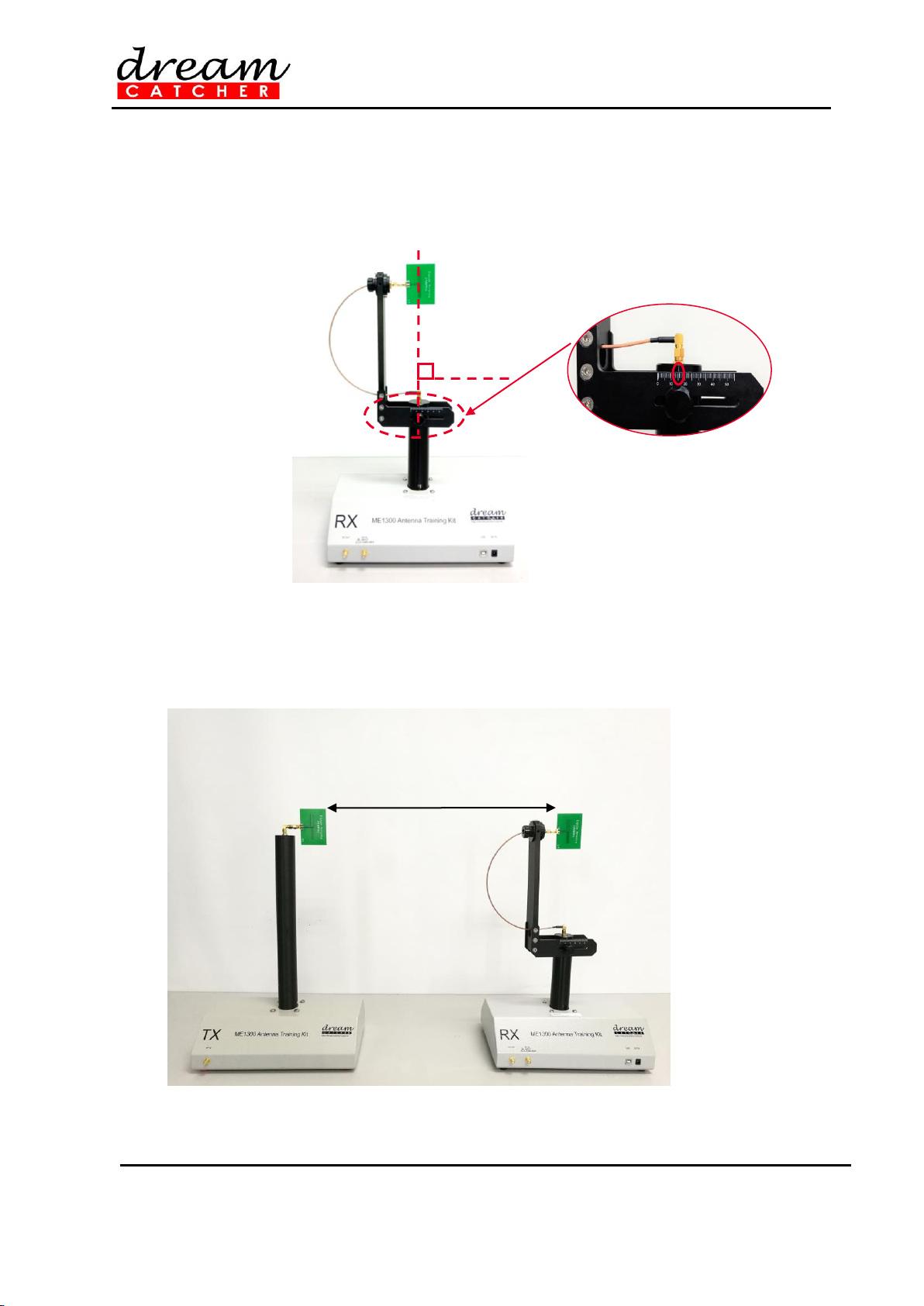
7. Use another RF coaxial cable to connect the RF OUT connector of the receiver module (Rx) to
the RF IN connector of the N9912A.
8. Adjust the distance between the antennas to 50 cm and make sure that they are in the far-field
region. Record the distance and the heights of the antennas in the corresponding record form as
given in Appendix A.
9. Connect the Type A-to-Type B USB cable to the receiver module (RX) and PC.
10. Plugin the 5 V power adaptor to the receiver module (RX).
11. Connect the LAN cable to the Keysight N9912A FieldFox RF analyzer and PC.
12. Turn on the 5V power adaptor and Keysight N9912A FieldFox RF analyzer.
13. Open the RadPat v4 software. Click the Settings button and click Connect.
14. Set the start frequency to 2375 MHz and the stop frequency to 2425 MHz under the RF
(Frequency Range.
15. Set Frequency of Interest to 2400 MHz. This is the frequency of the antenna-under-test (AUT).
16. Click Configure to enter the instrument setting configuration and click Save & Exit. This will bring
the rotator back to its home position and configure the N9912A settings.
17. After the homing operation and the N9912A configuration have completed, the window will return
to the RadPat v4 main interface and the main panel will be enabled.
Figure 5 –Main panel
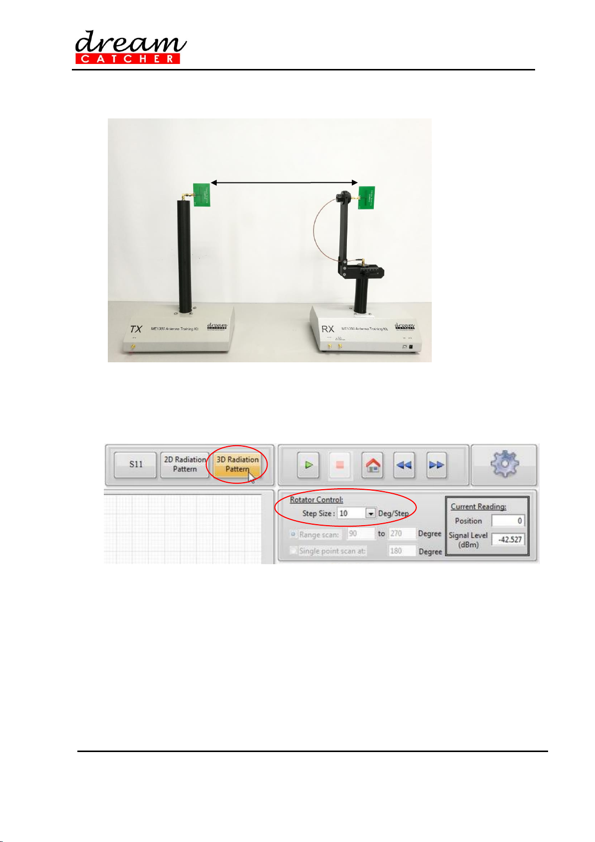
18. Click 2D Radiation Pattern, set the Step Size under the Rotator Control panel to 10 Deg/Step
and set the Range Scan from 0 to 350 degrees.
19. Click Play on the main panel to begin plotting the antenna radiation pattern.
20. After the plotting finished, click Add under the Marker panel to add a marker. You should see a
new entry of Marker 1 added under the Marker panel. Triple-click on the row of the newly added
entry under the Plot column until a drop-down box appears. Then, select Plot 1 to assign the
marker to the plotted radiation pattern.
21. Drag the marker to Position (Degree) 0 using the mouse. Then, record the reading shown under
the Marker panel under the dB column into Appendix A. Repeat this step and increase the
position by 10 degrees until it reaches 350 degrees.
22. Determine the value of max PR, based on the radiation pattern plotting, and calculate the
Normalized (dB) value for each step.
23. Using the polar chart in Appendix A, hand plot the antenna radiation pattern and normalized data
recorded. Compare the hand-plotted antenna radiation pattern with the one plotted using the
RadPat v4 software.
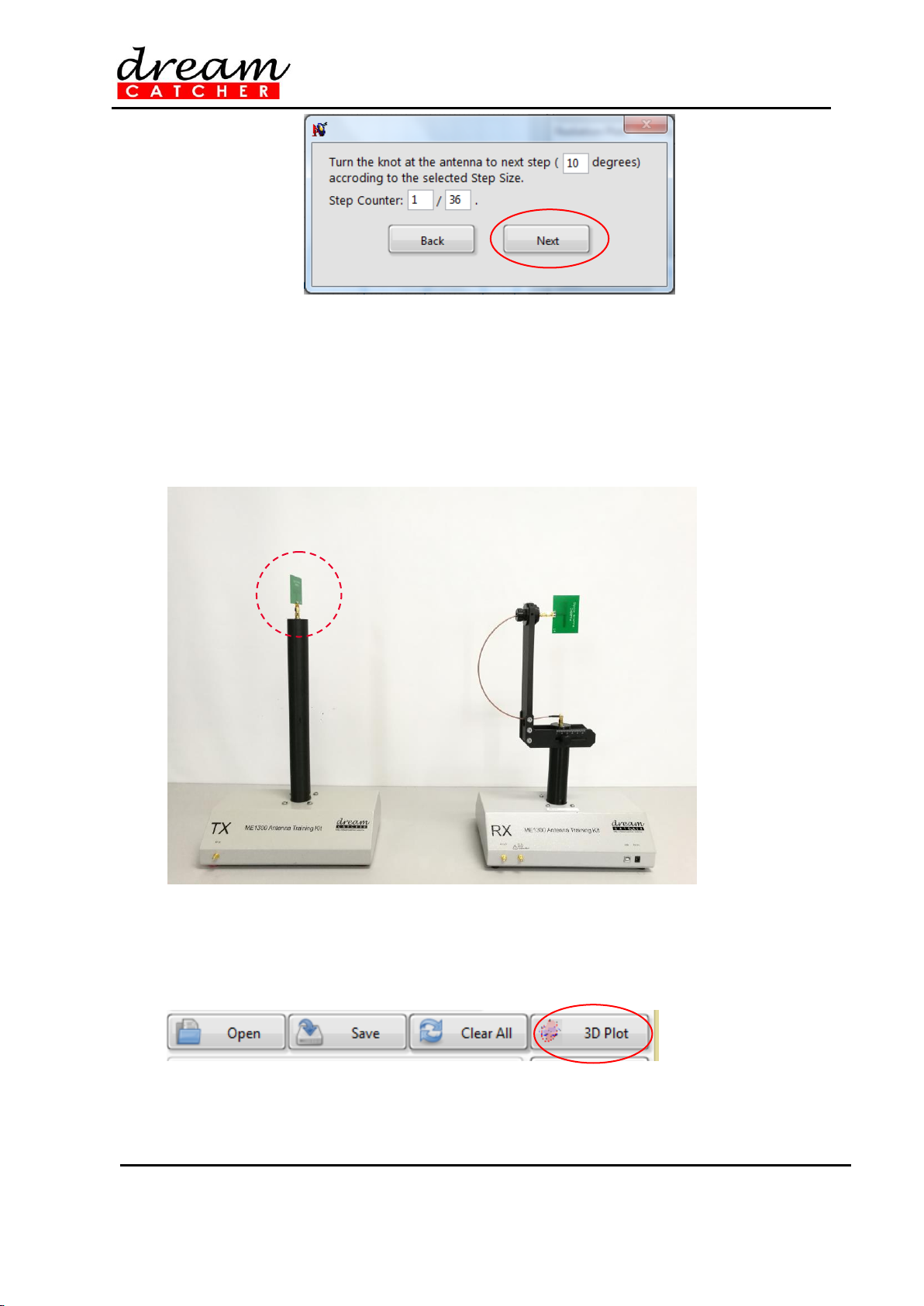
24. Save the radiation pattern plot by clicking the Save button. A dialog box showing the file path of
saved plot should appear.
25. You may open the saved file (.csv file) using Microsoft Excel for further analysis.