2
Introduction
Thank you for choosing AVIT! This ulti-protocol “PassThru” vehicle interface tool lets your PC
co unicate and perfor ECU reprogra ing on any odern heavy duty vehicle diagnostic
bus.
This Quick Start Guide covers only the initial setup of the AVIT. Refer to the AVIT Manual
online for full docu entation of all features and procedures.
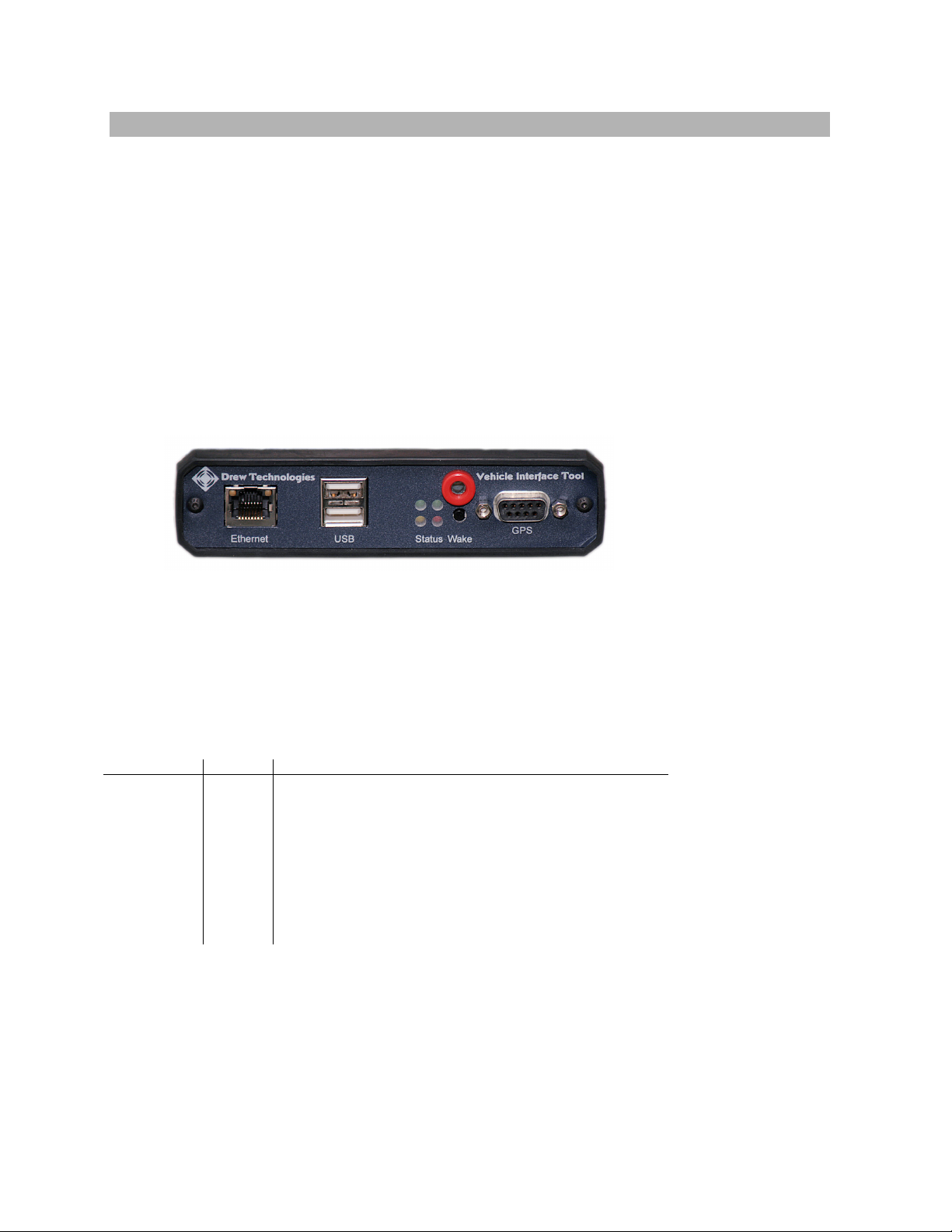
AVIT Advanced Pass-Thru Device
AVIT is a partially co pliant SAE J2534-1 PassThru device that incorporates any optional
features published in J2534-2. As a PassThru device, it can be connected to a laptop, PC, or
network and incorporates the following features:
• A CAN channel for J1939 or 500K CAN (passenger vehicles)
• A J1708 and J1587 link
• A J1850 link
• A second CAN channel, dual or single wire
• Software controlled low power odes for in vehicle onitoring
• Wake input anual switch or Ignition input
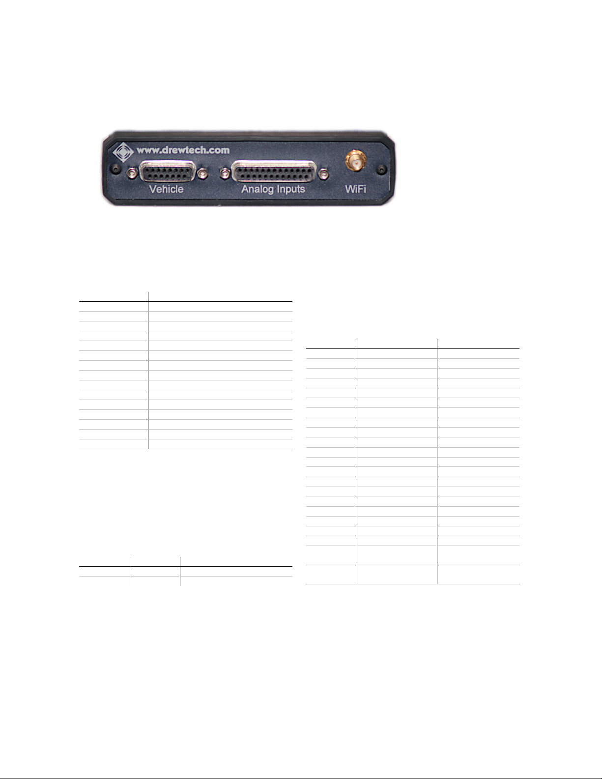
• Optional internal Wireless Ethernet as a host interface
• 16 general purpose analog inputs
• 4 Digital input and 4 Digital outputs
• The rugged alu inu case, standard connectors, extended te perature range and
non-slip rubber end caps ake AVIT ideal for in-vehicle testing and other harsh
environ ents.
AVIT and RP1210
Drew Technologies also offers a RP1210 DLL that allows the AVIT to work with existing
RP1210 applications.
AVIT for Vehicle Diagnostics
The AVIT has optional software available fro both Drew Technologies and third parties for
data logging, diagnostics and easure ent. Drew Technologies offers a licensable API called
JVCI that developers can use to collect sensor data fro passenger vehicles. This API, when
integrated with a GUI application, can reduce the need to instru ent vehicles with external
sensors by collecting data directly fro the in-vehicle network.
AVIT for ECM Re rogramming
Because J2534-1 and RP1210 are widely accepted standards, the AVIT will work with a variety
of ECM reprogra ing applications. The EPA-Published regulation has led to publicly available
reprogra ing applications fro al ost every ajor auto aker. These applications will allow
independent repair shops to update the calibrations on newer heavy-duty vehicles and
passenger vehicles.