Daikin RTD-10 User manual

Standard Control: Resistance
In Resistance Control Mode the RTD-
10 Inputs allow individual control of
a/c unit operating parameters using
resistance values. ach input
corresponds to a specific unit setting
shown in the table below If an input is
left unconnected then the
corresponding setting will remain at
the default value.
S1 Setpoint 0..10kΏ : 16..32°C (22)
S2 Fanspeed Low<=1.1kΏ, High=2.2kΏ, HighHigh*=3.3kΏ
S3 Mode Auto<=1.1kΏ, Heat=2.2kΏ, Fan=3.3kΏ, Cool=4.7kΏ, Dry=6.8kΏ,
S4 Louvre Swing<=1.1kΏ, 0°=2.2kΏ, 20°=3.3kΏ, 70°=4.7kΏ, 90°=6.8kΏ,
S5 On/off On = Closed Circuit, Off = Open Circuit
S6 Unlock Lock All<=1.1kΏ, Lock Setpoint, Mode, On/Off= 2.2kΏ, Lock
Mode,On/Off=3.3kΏ, Lock On/Off=4.7Ώ, Local=6.8kΏ, Lock
Mode=9.6kΏ, Unlock>15kΏ
*HighHigh fanspeed operates if available, otherwise selects High fanspeed
S1 kΏ 0.3 0.9 1.5 2.1 2.6 3.2 3.8 4.4 5.0 5.6 6.2 6.8 7.4 7.9 8.5 9.1 9.7
R1 Run/
Defrost
Run: SW1.3 OFF : Closed when unit switched ON
Defrost: SW1.3 ON : Closed when unit in defrost
R2 Fault Closed on any unit fault
Caution: Relays rated for maximum 1A, 24VAC/30VDC
Resistances should be within +/-250 ohms of the quoted value. Open circuit is R>200kΩ.
S1 in resistance mode is designed to be operated using a linear 10kΩ variable resistance.
It is recommended that volt-free contacts or switch mechanisms have gold plated contacts to ensure a low
resistance circuit when the switch is made.
S1 to S6 cables should be 0.5 to 1.0 mm2 multi-stranded screened twisted pair. The screen should be earthed
at one end only. The maximum distance from the RTD-10 to the input source is 200m.
Mounting
88.00
78.00
Ø 5.00
MOUNTING PILLARS
The RTD-10 is supplied with 4
mounting pillars that can be used to
mount the interface within units with
compatible mounting holes
SCR W MOUNTING
The RTD-10 can be mounted using
screws of up to 5mm diameter.
The RTD-10 can be mounted horizontally or vertically.
ower Supply
The RTD-10 requires a 15V to 24VDC power connection. Power can be
supplied from VRV indoor unit PCB X18A connection , a Skyair indoor unit
PCB X35A connection or VAM PCB X11A connection. A 1m cable and
connector is supplied with the RTD-10.
RTD-10 Description
The RTD-10 is a monitoring and control interface for Daikin VRV and Skyair
ranges of air-conditioners; and VAM and VKM ventilation units. The interface is
compatible with all units that have a P1,P2 remote controller network
connection and allows control of up to 16 units in a single group.
Control Functions
HARDWIR D CONTROL. Unit control can be achieved through resistance
inputs using resistor, potentiometer and volt-free contact inputs.
BMS INT GRATION. Unit control can be achieved through 1-10V voltage
inputs integrated with BMS control outputs.
H ATING INT RLOCK. Units can be interlocked with external heating
systems.
DUTY/STANDBY. Multiple groups can be operated with rotating duty/standby
with fault and high temperature alarming.
MODBUS CONTROL. The RTD supports the Modbus Protocol for network
control and monitoring.
CUSTOM CONTROL. RTD interfaces can be supplied in custom configurations
to suit specific applications.
Warnings and Cautions
Do not exceed the specified fault relay ratings
Observe precautions for handling Electrostatic
Sensitive Devices
RTD-10 Control Interface v1.04
Installation and Operating Instructions
1, 2 Network
Terminals P1, P2 connect to the Daikin P1, P2 network. P1,P2 installation
should follow Daikin installation specifications. The RTD-10 can operate in
Master or Slave mode with any Daikin remote controller. Operation is also
possible without a remote controller being connected. Note that infra-red
receivers must be configured to operate in slave mode.
The RTD-10 can be configured to operate in several different modes using the
configuration DIP switches SW1.1 to SW1.4. In Standard Control the following
combinations of modes are available:
Input
Mode
5678
ON
1 2 3 4
Resistance
5678
ON
1 2 3 4
Voltage
Relay R1
Output
5678
ON
1 2 3 4
Unit Run
Unit Run
5678
ON
1 2 3 4
Defrost
Operation
Setpoint
Limit
5678
ON
1 2 3 4
No Limit
5678
ON
1 2 3 4
Limit 19 to 23
S1 S2 S3 S4 S5 S60V 0V
S1
S2
S3
R SISTANC MOD
S4
S5
S6
5 6 7 8
ON
1 2 3 4
Standard Control
Indoor Unit
Remote
Controller
(master)
P1 P2P1 P2P1 P2 P1 P2
upto 16 units
Indoor Unit
RTD
0V +V
OWER
15-24VDC
0V+V
X18A
VRV
Indoor
PCB
R D
BLU
0V +V
OWER
15-24VDC
0V+V
X35A
Skyair
Indoor
PCB
R D
BLU
100.00
100.00
22.00
1
J2
L D5 L D6
L D4L D3
L D1 L D2
SW1
All dimensions in mm
5678
ON
1 2 3 4
S4 S5 S60VS1 S2 S30V
RS485 D-BUS
GND
R2
0 +
R1
0 +
0V +V
OWER
15-24VDC
DB
+DA
-
REMCON
P1 P2
Daikin Control Interface
RTD-10

Standard Control: Voltage
In Voltage Control Mode the RTD-10
Inputs allow individual control of a/c
unit operating parameters using
voltages. ach input corresponds to a
specific unit setting shown in the
table below If an input is left
unconnected or is set to 0 Volts then
the corresponding setting will remain
at the default value.
Input Name Range (default / 0V value)
S1 Setpoint 1..10V : 16..32°C (22)
S2 Fanspeed Low=1.75V, High=3.25V, HighHigh*=4.75V
S3 Mode Auto=1.75V, Heat=3.25V, Fan=4.75V, Cool=6.25V, Dry=7.75V,
S4 Louvre Swing=1.75V, 0°=3.25V, 20°=4.75V, 70°=6.25V, 90°=7.75V,
S5 On/off On >=5V, Off = 0V
S6 Unlock Lock All=1.75V, Lock Setpoint, Mode, On/Off=3.25V,
Lock Mode, On/Off=4.75V, Lock On/Off=6.25V,
Local=7.75V, Lock Mode=9.25V, Unlock=10.0V
*HighHigh fanspeed operates if available, otherwise selects High fanspeed
Output Name Operation
R1 Run/
Defrost
Run: SW1.3 OFF : Closed when unit switched ON
Defrost: SW1.3 ON : Closed when unit in defrost
R2 Fault Closed on any unit fault
Caution: Relays rated for maximum 1A, 24VAC/30VDC
Voltages should be within +/- 0.25V of the quoted value. Open circuit for V<1V.
The RTD-10 can be configured to operate in Heating System Interlock mode
to prevent A/C cooling or heating operation from conflicting with the operation
of an additional system. The RTD-10 can be wired to operate either in Master
mode in which the RTD-10 determines when the secondary system operates,
or Slave mode in which the secondary system will inhibit the RTD-10 operation.
Inputs are the same as Resistance Control Mode, with input S4 changed to act
as an operation inhibit input signal. Closed circuit inputs on S1 to S3 select
additional functions and override the default behaviour of the input.
Input Name Range (default)
S1 Setpoint 0.3..10kΏ : 16..32°C (22)
Restart Inhibit = Closed Circuit (Setpoint Control not available)
S2 Fanspeed Low=1.1kΏ, High=2.2kΏ, HighHigh*=3.3kΏ
Invert S4 Input = Closed Circuit (Fanspeed Control not available)
S3 Mode Auto=1.1kΏ, Heat=2.2kΏ, Fan=3.3kΏ, Cool=4.7kΏ, Dry=6.8kΏ,
Heat/Cool Mode Inhibit = Closed Circuit (Mode Control not available)
S4 Inhibit Inhibit=Closed Circuit, Enable = Open Circuit
S5 On/off On = Closed Circuit, Off = Open Circuit
S6 Unlock Lock All<=1.1kΏ, Lock Setpoint, Mode, On/Off= 2.2kΏ, Lock
Mode,On/Off=3.3kΏ, Lock On/Off=4.7Ώ, Local=6.8kΏ, Lock
Mode=9.6kΏ, Unlock>15kΏ
*HighHigh fanspeed operates if available, otherwise selects High fanspeed
Output Name Operation
R1 Mode
Interlock
SW1.3 OFF: Closed if Mode Auto:Cool, Cool or Dry + Unit On
SW1.3 ON: Closed if Mode Auto:Heat or Heat + Unit On
R2 Fault Closed on any unit fault
Caution: Relays rated for maximum 1A, 24VAC/30VDC
INT RLOCK MAST R MOD
To operate the RTD-10 in Interlock Master Mode the relay output R1 is wired
as an input to the secondary system. With SW1.3 OFF R1 will close when the
unit is On and in a cooling mode. With SW1.3 ON R1 will close when the unit is
On and in a heating mode. If the unit is in fault then R1 will not operate.
Heating Interlock
: Master
R1
Mode
Interlock
Heating System Inhibit
Relay Closed = Unit ON + No Fault
+ Mode = Auto:Cool, Cool or Dry
5 6 7 8
ON
1 2 3 4
Heating Interlock
: Master
Cooling System Inhibit
5 6 7 8
ON
1 2 3 4
R1
Mode
Interlock
Relay Closed = Unit ON + No Fault
+ Mode = Auto:Heat or Heat
INT RLOCK SLAV MOD
To operate in slave mode the input S4 operates as a Volt-free inhibit input.
When the inhibit signal is closed circuit the RTD-10 will prevent the A/C unit
from operating. Input S4 operation can be inverted by inserting a Short Circuit
on input S2.
The RTD-10 can be configured using switch SW1.4 to switch the A/C units
OFF during the inhibit or to switch the units to FAN-ONLY or Mode Inhibit. The
inhibit signal overrides on/off commands both from the Remote Controller as
well as input S5. If A/C Fan-Only mode is selected then the unit will remain on
and the unit mode will be switched to Fan-only and locked. If Mode Prohibit is
selected then the Mode will be prevented from operating in Auto and Heat if
Heating Inhibit is selected (SW1.3 OFF), and will be prevented from operating
in Auto, Cool and Dry if Cooling Prohibit is selected (SW1.3 ON).
Run Interlock
: Slave
S4
Inhibit
A/C Inhibit
Relay Closed = Inhibit A/C
A/C
OFF
5678
ON
1 2 3 4
S1 S2 S30V
S1 S2 S30V
Relay Open = Inhibit A/C
S1 S2 S30V
Fan-Only Interlock
: Slave
S4
Inhibit
A/C Inhibit A/C
FAN-ONLY
5 6 7 8
ON
1 2 3 4
Relay Closed = Inhibit A/C
S1 S2 S30V
Relay Open = Inhibit A/C
S1 S2 S30V
S1 S2 S30V
Heat/Cool Interlock
: Slave
S4
Inhibit
A/C Inhibit Mode
Prohibit
5 6 7 8
ON
1 2 3 4
Relay Closed = Inhibit A/C
S1 S2 S30V
Relay Open = Inhibit A/C
S1 S2 S30V
S1 S2 S30V
Fan Dry Auto Cool Heat
5678
ON
1 2 3 4
5678
ON
1 2 3 4
Heat
Prohibit
Cool
Prohibit
When the inhibit signal is removed the RTD-10 will restore the previous
operating state of units. If input S1 is Short Circuited then the previous settings
will not be restored when the interlock is removed.
S1 S2 S3 S4 S5 S60V 0V
VOLTAG MOD
S1
S2
S3
S4
S5
S6
5 6 7 8
ON
1 2 3 4
Standard Control: Relay R1 Output
SW1.3 configures Relay R1 as either a Run signal that closes when the unit is
enabled to run, or a Defrost signal that indicates when the unit is in Defrost.
Standard Control: Setpoint Limit
If SW1.4 is ON then a setpoint limit of 19 to 23 degrees is applied to setpoint
adjustments made from the Remote Controller or Central Controller. Setpoint
Limiting only applies when the setpoint buttons are unlocked and the keypad
Unlock input S6 is NOT set to Local. The setpoint limits are not applies to
setpoint control from input S1 or adjustment via Modbus commands.
Standard Control: Remote Controller Unlock
Input S6 in Voltage or Resistance mode can configure the unlock state of the
Remote Controller buttons. The default state is Unlock, in this state the
Remote Controller buttons are all active and no lock symbol appears on the
display. Updates from inputs S1 to S5 are only sent when the input changes so
that users can still operate the A/C. Setting S6 to Locked locks all input
buttons and updates from the inputs S1 to S5 will control the operation of the
A/C. Several partial Lock states allow combinations of the Setpoint, Mode and
On/Off buttons to be locked so that the user has partial control of the unit.
Setting S6 to Local unlocks all remote controller buttons and prevents any
control updates from inputs S1 to S5.
Heating System Interlock

The RTD-10 can be configured to operate in a duty/standby configuration
suitable for IT and Telecoms applications. An RTD-10 master together with up
to 7 RTD-10 slaves can be configured to operate in a rotating duty/standby
configuration with the following features:
●Up to 8 duty/standby groups
●All units run on fault
●1 or 2 standby units
●Daily, Weekly or Multi-week duty rotation
●Two level alarm on high temperature and unit fault
●Thermistor space temperature alarm
●A7 (Louvre) fault code filtering
DUTY/STANDBY OP RATION
Under 'no fault' conditions the system will operate with 1 or 2 units in standby
and the remaining units operational (2 unit standby is only available if there are
at least thee RTD groups). Default rotation time is 7 days, input S3 can be
configured to select rotation times of 1 day, 2 weeks or 4 weeks if required
using specific resistor values. In addition a test-mode is available by placing a
0 ohm link on S3 which will cause the system to operate in test mode with a 60
second rotation time. The system should only be operated in test mode for
short time periods.
The RTD-10 with Address 0 (SW1.5 to SW1.8 OFF) is the Duty/Standby
master. All inputs and outputs are wired to the Master. Slave inputs should not
be wired. Slave output relays indicate the Alarm Level for that slave only.
A/C UNIT OP RATION
The unit mode is set to COOL and the mode button on the Master remote
controller is locked to prevent change. The on/off button is also locked. The
setpoint and fanspeed can be set from the RTD-10 master or the remote
controller on the master group. If S1 and S2 are wired then setpoint and
fanspeed are set by the RTD-10 inputs and the corresponding buttons on the
remote controller are locked. If S1 and S2 are not wired then the buttons on the
master remote controller are unlocked and can be used to set operating
values. In this mode the setpoint is limited to the range 20 to 32°C.
Duty/Standby Operation
ALARM OP RATION
Relay outputs R1 and R2 on the Master RTD-10 operate respectively as Level
1 and Level 2 alarm outputs. If a Level 2 alarm occurs then both R1 and R2 will
be closed. All units will run if a Level 1 or Level 2 alarm occurs.
All unit return air temperatures are monitored and alarm levels 1 and 2 are set
respectively at 2°C and 4°C above operating setpoint. The Auxiliary Space
Temperature sensor has the same alarm limits applied.
Any unit fault other than code A7 will result in a Level 2 alarm being generated.
An A7 (louvre fault) will generate a Level 1 alarm, but will not force units on.
The RTD-10 master will monitor all of the RTD slave devices discovered after
power-up. If any of the RTD slave devices fail to respond the RTD-10 will raise
a Level 2 alarm after 1 to 2 minutes.
Alarm Reasons
Alarm Level 1
Output R1
Unit Return Air > Setpoint + 2°C
Aux. Space Temperature > Setpoint + 2°C
A/C Unit Louvre Fault (A7)
Alarm Level 2 xists
Alarm Level 2
Output R2
Unit Return Air > Setpoint + 4°C
Aux. Space Temperature > Setpoint + 4°C
A/C Unit Fault (except A7)
A/C Unit Missing (U5 Fault)
RTD-10 Slave Missing (master RTD-10)
RTD-10 No slaves found (master RTD-10)
RTD-10 Master not found (slave RTD-10)
If a Level 1 or Level 2 alarm occurs due to a unit or communications fault then
all units will run until all faults are cleared.
If a Level 1 or Level 2 alarm occurs due to a high temperature on an indoor unit
or the Auxiliary Space sensor then all units will run until temperature has reset
and will continue to run on for 20 minutes before reverting to normal
Run/Standby operation. In Test Mode (rotation = 60s) the run on time will be 40
seconds..
If a Level 2 alarm occurs due to an Indoor Unit Fault then all units will run until
the Indoor Unit Fault has cleared and will continue to run on for 10 minutes
before reverting to normal Run/Standby operation. In Test Mode (rotation =
60s) the run on time will be 20 seconds.
OV RRID ALL ON/OFF
Input S5 is a volt-free contact input that overrides all units ON if closed circuit.
Input S6 is a volt-free contact input which overrides all units OFF if closed
circuit.
AUXILLIARY SPAC S NSOR
An auxiliary space sensor is required to provide alarm monitoring in the
controlled space.
The sensor should be a 10kΏ NTC Thermistor mounted on a suitable vertical
surface in the monitored space. The sensor should be wired to the RTD-10
using a twisted pair cable no longer than 100 metres. The Auxiliary sensor will
raise alarms even if the units are overridden off.
Duty/Standby Operation
INSTALLATION
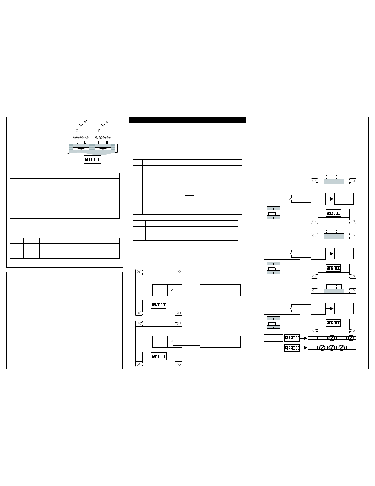
All RTD interfaces must be networked together using the 3 wire RS485
network, each RTD must then have a network address set in the range 0 to 7
(see section RTD Networking). The RTD-10 Duty/Standby Master must have
an address of 0. The remaining RTD slaves should have addresses in the
range 1 to 7. If there are less than 7 slaves then start the addressing at 1 and
allocate each slave consecutively upwards.
The Master and Slave RTD-10s will both initially indicate a Level 2 alarm. The
master alarm will clear when it discovers at least one slave RTD-10. The slave
alarm will clear when the master discovers the slave. If communications fails
with a slave RTD-10 the master will generate a Level 2 alarm after 120s.
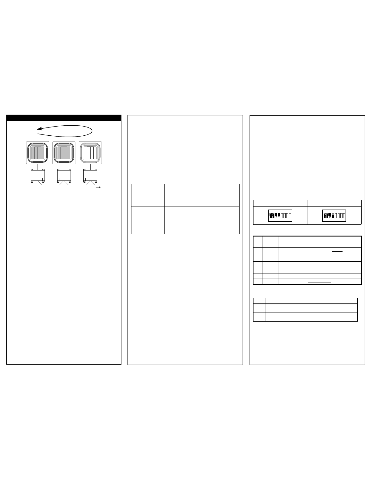
CONFIGURATION
The Run/Standby configuration is selected using the RTD-10 DIP switch
settings. Both master and slave devices must have the DIP switches set. The
position of SW1.4 on the master determines whether the system operates with
1 unit or 2 unit standby. The possible switch configurations are as follows:
1 Unit Standby 2 Unit Standby
5 6 7 8
ON
1 2 3 4
5 6 7 8
ON
1 2 3 4
INPUT CONFIGURATION
Input Name Range (default)
S1 Setpoint 0..10kΏ : 16..32°C (from RC)
S2 Fanspeed Low=1.1kΏ, High=2.2kΏ, HighHigh*=3.3kΏ (from RC)
S3 Rotation 60s<=1.1kΏ, 1 Day=2.2kΏ, 1 Week=3.3kΏ, 2 Weeks=4.7kΏ,
4 Weeks=6.8kΏ
S4 Auxiliary
Space
Temp
10kΏ NTC Thermistor
Recommended part: RS Stock No. 813-806
S5 All On All On = Closed Circuit, Normal Operation = Open Circuit
S6 All Off All Off = Closed Circuit, Normal Operation = Open Circuit
*HighHigh fanspeed operates if available, otherwise selects High fanspeed
R LAY CONFIGURATION
Output Name Operation
R1 Alarm
Level 1
Closed when Alarm Level 1 or 2 occurs
R2 Alarm
Level 2
Closed when Alarm Level 2 occurs
Caution: Relays rated for maximum 1A, 24VAC/30VDC
MODBUS OP RATION
When operating in Duty/Standby mode the RTD devices CANNOT be
connected to an external Modbus Master as this will disrupt operation.
Duty/Standby Operation
7 Day Rotation
RUN RUN STANDBY
RTD-10 RTD-10 RTD-10
P1,P2 P1,P2 P1,P2
RS485 Upto 8 Groups

RTD Networking
ADDR SSING
The RTD-10 has the facility to create control groups using multiple
RTDs connected together on the RS485 D-Bus network. In standard
configuration up to 16 RTD-10 devices can be connected together.
ach RTD is assigned a D-Bus address using the configuration
switches SW1.5 to SW1.8. Unit addresses are shown below.
5678
ON
1 2 3 4
ADDR SS 0 ADDR SS 1 ADDR SS 2 ADDR SS 3
ADDR SS 4 ADDR SS 5 ADDR SS 6 ADDR SS 7
ADDR SS 8 ADDR SS 9 ADDR SS 10 ADDR SS 11
ADDR SS 12 ADDR SS 13 ADDR SS 14 ADDR SS 15
5678
ON
1234 5678
ON
1 2 3 4 5 6 7 8
ON
1 2 3 4
5678
ON
1 2 3 4 5 6 7 8
ON
1234 5678
ON
1 2 3 4 5 6 7 8
ON
1 2 3 4
5678
ON
1 2 3 4 5 6 7 8
ON
1234 5678
ON
1 2 3 4 5 6 7 8
ON
1 2 3 4
5678
ON
1 2 3 4 5 6 7 8
ON
1234 5678
ON
1 2 3 4 5 6 7 8
ON
1 2 3 4
Address 0 is the RTD-10 MAST R address. Address 1 to 15 are RTD-
10 SLAV addresses.
N TWORK INSTALLATION
The RS485 D-Bus network requires a twisted pair cable connecting
terminals DB(+) and DA(-) on each RTD as shown below. Terminal DB
must be connected to all other DB terminals. Terminal DA must be
connected to all other DA terminals. In addition the common terminal
GND on all devices must be connected together. If a shielded cable is
used then the shield can be used for this purpose. It is recommended
that the GND connection is connected to local arth at one point only.
The network must be installed as a daisy-chained point-to-point Bus
configuration, Star and Ring connections must NOT be used.
5 6 7 8
ON
1 2 3 4
ADDRESS 0 ADDRESS 1
5 6 7 8
ON
1 2 3 4
RS485 D-BUS
DB DA GND
+ -
RS48 5 D-BUS
DB DA GND
+ -
DB(+) DB(+)
DA(-) DA(-)
GND GND
SP CIFICATION
Use stranded 24awg shielded or unshielded twisted pair to Cat3, Cat4
or Cat5 specification. Use a twisted pair for connections DB,DA and an
extra core for connection GND.
N TWORK L NGTH
Standard installation for total network distances of up to 500m can be
achieved following the basic daisy-chaining method showed in the
above diagram. The network can be extended further using RS485
repeaters.
CONTROL
The RTD-10 can be operated from both
the hard-wired inputs and Modbus register
commands if input S6 is open-circuit.
Under this mode of operation control
updates will be sent if a change is made to
either a Modbus register or a wired input.
All control registers are analogue Holding
Registers
Holding
Register
Name Range
0001 Setpoint 16..32
0002 Fanspeed 1..3 (1:Low, 2:High1, 3: High2*)
0003 Mode 0..4 (0:Auto, 1:Heat, 2:Fan, 3:Cool, 4:Dry)
0004 Louvre 1..7 (1:Swing, 2: 0 Degrees, 3: 20 Degrees, 4:45 Degreees,
5:70 Degrees, 6:90 Degrees )
0005 OnOff 0..1 (0:Off, 1:On)
*Where HighHigh fanspeed is enabled, High1 = High, High2= HighHigh. Otherwise both modes select High
Holding
Register
Name Lock Mode*
0010 All Lock 0:LastTouch,1:Central,2:Local,3:OnChange
0011 Setpoint Lock 0:LastTouch,1:Central,2:Local,3:OnChange
0012 Fanspeed Lock 0:LastTouch,1:Central,2:Local,3:OnChange
0013 Mode Lock 0:LastTouch,1:Central,2:Local,3:OnChange
0014 Louvre Lock 0:LastTouch,1:Central,2:Local,3:OnChange
0015 OnOff Lock 0:LastTouch,1:Central,2:Local,3:OnChange
*Last Touch updates are written to the A/C on every register write. On Change updates are only sent if the
value written changes. Central locks the corresponding RC button. Local unlocks the RC button and prevents
any updates from the RTD.
MONITORING
Unit data is available for each of the indoor units on the P1,P2 network. All
readback data is available in analogue Input Registers. Input registers are
numbered using the indoor unit number x 100 added to an offset relating to a
specific feature. Group data is available as unit 0.
Group* Unit 1 Unit 2 ... Unit16 Name Range
0020 0120 0220 ... 1620 Unit xists 0..1
0021 0121 0221 ... 1621 Is Fault 0..1
0022 0122 0222 ... 1622 Fault Code 0..65535
0023 0123 0223 ... 1623 Return Air Temp Degrees C x 100
* Group Unit Exists returns the number of units found. Group Fault Code returns the fault code of the first unit
in fault. Group Return Air Temp returns the average unit temperature.
FAULT COD S
Fault codes are encoded using a standard table to allow standard Daikin fault
codes to be generated from the readback value. The no fault value is 255.
K YPAD LOCK
When the keypad is locked using input S6 then Modbus commands will not
change the lock state but unit settings can still be adjusted. When the S6 input
is set to unlock the keypad then Modbus commands can change the lock state.
Additional Mod us registers and more detailed Mod us engineering
instructions are availa le in the RTD-NET datasheet. availa le from
http://www.realtime-controls.co.uk/rtd. A full list of fault codes is also
availa le from this link.
MODBUS CONFIGURATION
Network 3 wire RS485
Mode Modbus RTU Slave
Baud 9600
Parity None
Stop bits 1
Note: RTD interfaces can e configured
with different aud rate and parity settings
if required
LED Functionality
Normal Operation
Key:
FLASHINGOFF ON
R
G
Power-Up sequence
Factory Configuration
R
G
No Fault State
R
G
Power-Up sequence
Custom Configuration
R
G
Unit Fault
R
G
P1,P2 Search. After
power-up and during
unit configuration
Error Conditions
R
G
Device configuration error
R
G
AC Unit Missing (U5 Fault)
R
G
RS485 Communications timeout
UNIT S ARCH
When the RTD-10 is powered up, or if it looses communication with the
Remote Controller the RTD-10 enters P1,P2 search mode. If P1,P2
communications are not re-established after 1 minute the RTD-10 will raise an
alarm which will be indicated on the fault relay output.
RTD-10 Datasheet Issue 1.04.01 © RealTime Control Systems Limited, 2010
Functional Specification
Electrical Environmental
Supply 15V-24V DC, 120mA
Regulated
Temperature
Storage -10oC to 50oC
ower <2.5VA Operation 0oC to 50oC
Relay 1A, 24VAC max
1A, 30VDC max
Humidity 0-90% RH
non-condensing
Mechanical rotection IP30
Dimensions H100 x W100 x D22 mm
EMC Emissions N61000-6-1
Mounting Four screw / pillar mounts EMC Immunity N61000-6-3
Inputs
Casing Zinc coated mild steel
Voltage Mode S1..S6 0..10VDC <1mA
Weight 120g Maximum Rating 12VDC
Connectors Rising clamp to 0.75mm2
cable
Resistance Mode S1..S6 5V, 1mA
Modbus Operation
VAM and VKM units can be switched on and off using the RTD-10 On/off input.
Control of VAM and VKM unit fanspeed and damper position from RTD-10
inputs or from Modbus registers is also possible using extended RTD-10
operating modes.
More details are availa le from http://www.realtime-controls.co.uk/rtd
VAM and VKM Unit Operation
Table of contents
Other Daikin Recording Equipment manuals