10
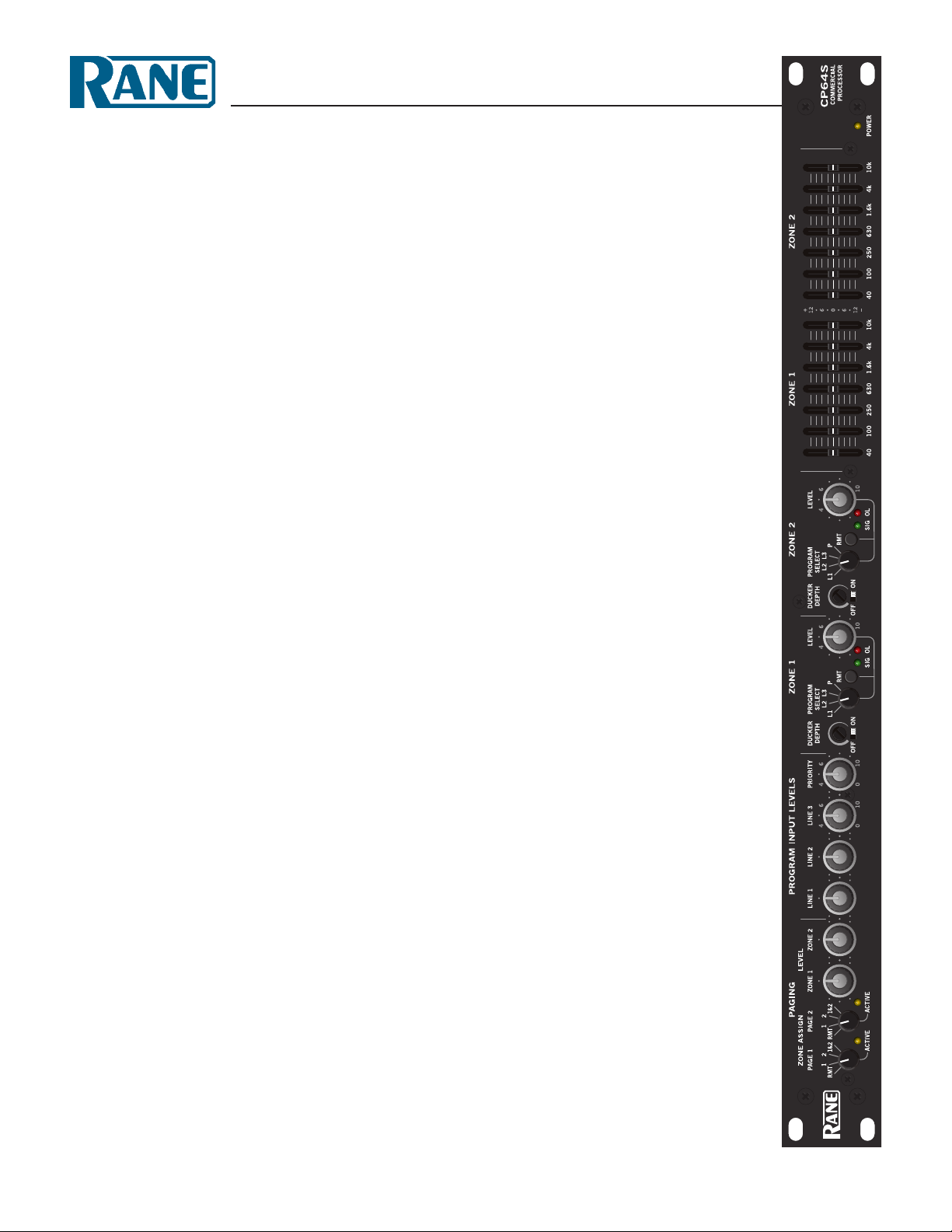
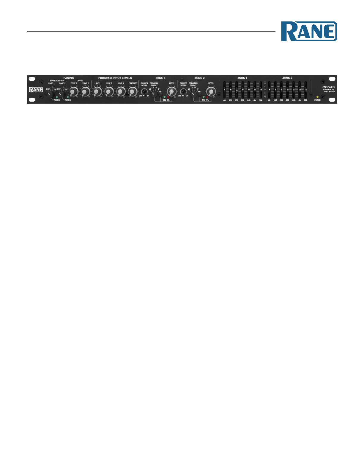
CP64S
COMMERCIAL PROCESSOR
3Page Priority Assign allows you to select one of the Page
Inputs as a Priority Page Input. e Priority Pager overrides the
non-priority Pager in the Zone(s) it is assigned. e non-priority
Pager may still broadcast in any Zone that the Priority Pager is
not assigned to or not currently broadcasting in. If a Page Input
is used for emergencies, set it as the Priority Pager. Set the switch
to P1 if you wish Page 1 to have priority over Page 2 (the default
setting). If you wish Page 2 to have priority over Page 1, set the
switch to P2. If NO is selected, neither Paging Input has priority
and both Pagers may be active at the same time. is allows the
Paging Inputs to mix for applications like karaoke or PA.
4 5 e Zone 1 Page and Zone 2 Page switches allow you
to sum Page signals with Program signals “Pre” (before) or
“Post” (after) the VCA. e VCA is used for Zone Level control
and Limiting. erefore, if you require the Page Level to be
controlled independent of the Program Level, set the switch for
that Zone to “Post.” is is the default setting, and is best for
emergency paging. If “Pre” is selected, Paging signals sum with
Program signals before the VCA. In this instance both Page
and Program signal levels are aected by the front panel ZONE
LEVEL control. Note the following:
• Zone Level, EQ and Limiter circuits do not aect Page signals
summed Post-VCA.
• Zone Level, EQ and Limiter circuits do aect Page signals
summed Pre-VCA.
• Page signals are not available on the Expand Zone output
when summed Post-VCA.
• Page signals are always available for the Expand Page output.
ere are two internal controls related to the Program Priority
detector:
6Priority Release Time 2 sec to 20 sec (trim pot)
Default: 12 seconds
7Priority reshold -∞ to -35 dBu (trim pot)
Default: -50 dBu
e default settings for the Program Priority detector are chosen
for most applications. Detector reshold settings lower than the
default setting of -50 dBu are prone to false triggering unless the
source is very quiet. If a source is noisy, you may wish to set the
threshold higher to prevent false triggering. e default Release
Time is 12 seconds. You may wish to decrease the Release Time
if the source is a TV, radio, satellite or other relatively constant
signal source. If you have a source like a jukebox, with relatively
long search times, you may wish to extend the Release Time.
ere is one internal control related to Zone 1:
8Zone 1 Mode Mono/Stereo Default: Stereo
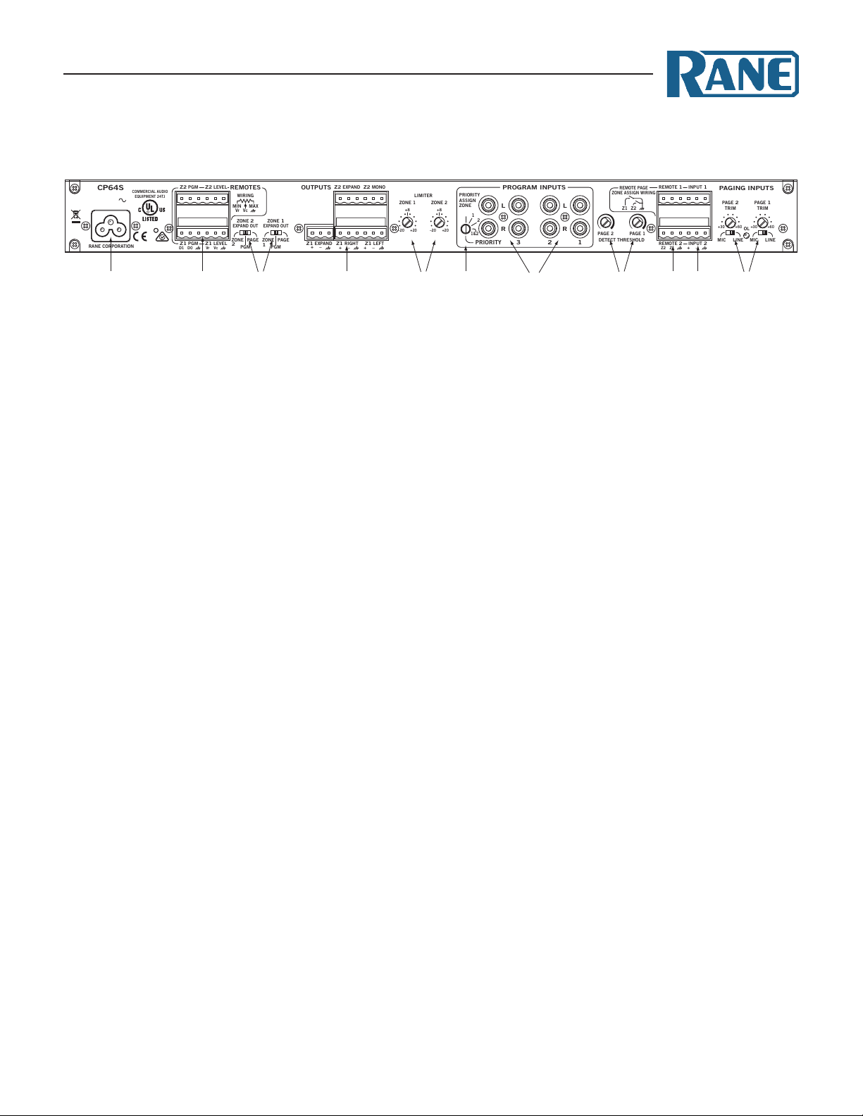
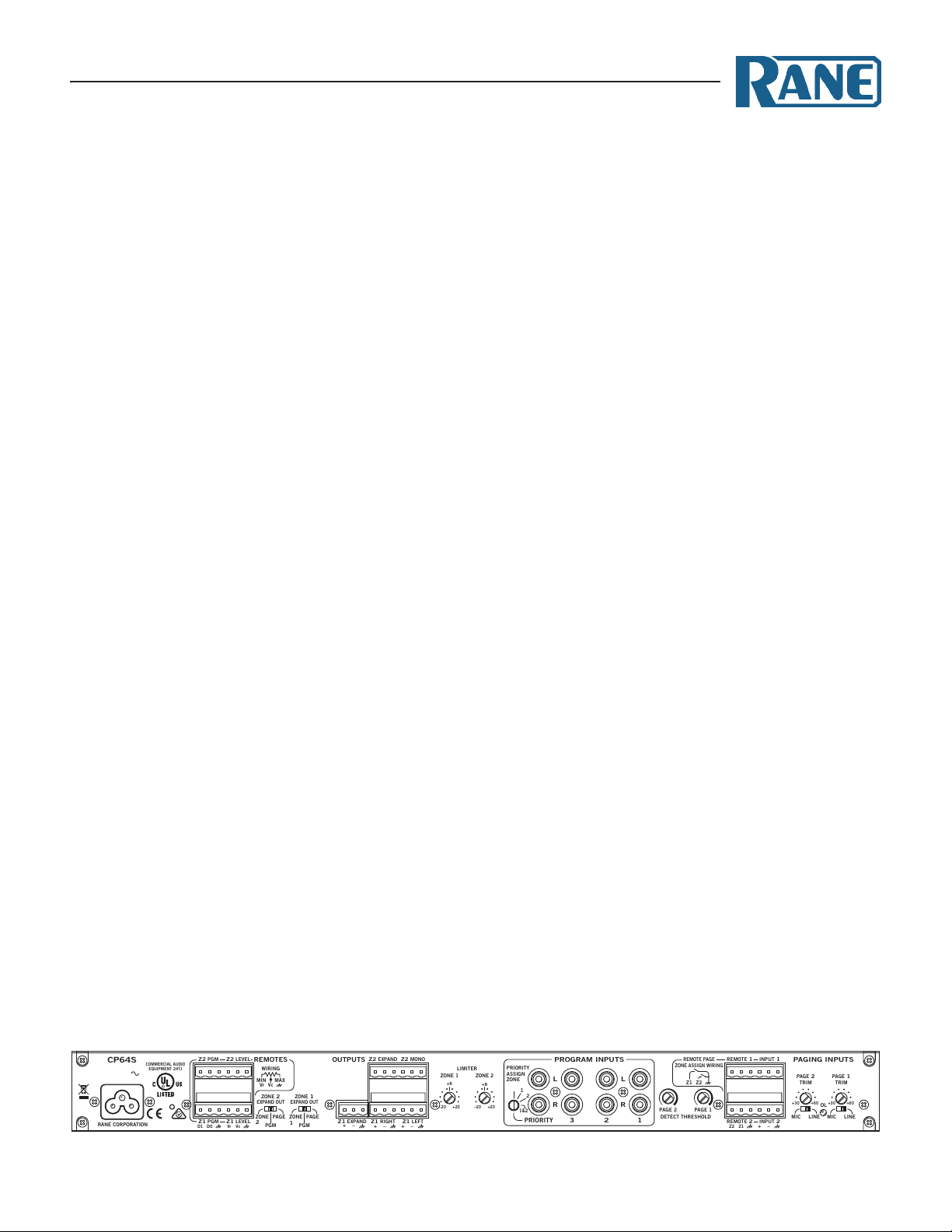
CP64S Connections
Do not connect the power cable to the CP64S until all connections
are made.
All Input and Output connections are made with Euroblock
connectors except for the RCA Program Inputs. When wiring
to Euroblocks, a minimum wire gauge of 22 is preferred for
reliability (maximum 12 guage). If the ground or shield wire
is left shorter, it acts as a strain relief for the other wires. Cable
with a exible jacket is easier to use and less likely to damage the
connections. Avoid stripping excess insulation. Inspect wires for
nicks that may lead to wire breakage. Fully insert each wire in
the appropriate socket and tighten the screw.
Page Input circuits operate balanced or unbalanced. Expand
and Zone Outputs are driven by cross-coupled line drivers and
operate balanced or unbalanced. For both Inputs and Outputs,
wiring is the same. Balanced operation is recommended, and
necessary when wire lengths are greater than 10 feet (3 meters).
Balanced wiring is (+) to (+), (–) to (–) and shield to shield.
For unbalanced operation, we recommend using two conduc-
tor cable with shield. e cable is wired to the CP64S the same
as for balanced operation. At the other end of the cable, connect
the (+) wire to signal “hot” and both the (–) and shield wires to
ground (important.)
If you use single conductor cable with shield, connect the
shield/gnd wire to both the (–) and shield pins at the CP64S. At
the other end of the cable connect the (+) wire to the signal “hot”
and the shield/gnd wire to ground. When unbalanced wiring is
used, it is very important for the CP64S and any other unit in
the system to have good earth or technical grounds. If a unit is
located more than 10 feet (3 meters) away from the CP64S or
is of a type that might create grounding problems, use isolation
transformers with unbalanced cable.
When operating cross-coupled line drivers unbalanced (i.e., any
CP64S Output), it is essential to ground the (–) pin.
e four stereo Program Inputs connect to RCA jacks. ese
Inputs are unbalanced. e same guidelines given above for
unbalanced operation apply to these Inputs.
Depending on building grounding, an occasional source of
system hum is powering sources and ampliers on dierent elec-
trical circuits. Try connecting everything on the same circuit.
See the RaneNote "Sound System Interconnection" on page
19 to answer any uncertainties, especially when using unbal-
anced sources.
REMOTE PAGE
ZONE ASSIGN WIRING
100-240 V
50/60 Hz 12 WATTS
off
ALL AUDIO AND
REMOTES ARE
CLASS 2 WIRING
COMMERCIAL AUDIO
EQUIPMENT 24TJ
R