Drone DR-2000 User manual

TM
DR-2000 Install Guide
Firstech, LLC.
21903 68th Avenue South
Kent, WA 98032
Phone/Téléphone: 888-820-3690
Fax/Télécopieur: 206-957-3330
Please visit www.dronemobile.com for additional information
Veuillez visiter www.dronemobile.com pour plus d’information.
Guide d’installation DR-2000

Table of Contents
1 | Copyright 2012 Firstech, LLC.
Introduction
Introduction and Notices 2
Type 1 - Standalone With RF Kit and Bypass
Type 2 - Data
Type 3 - Slave / Hardwire
4
5
6
Wiring Details
Dealer Activation
Suggested Mounting Locations
7
9
10
LED Diagnostics
Frequently Asked Questions 24
24
Wiring Diagrams
Details
Troubleshooting
TM DR-2000 Install Guide
Installation Overview
Programming
Remote Programming Routine
Valet Mode
Engine Sensing
Using FT-EZGO With DR-2000
Option Tables
Option Descriptions
Option Programming Instructions
3
11
11
12
13
14
17
20

TM DR-2000 Install Guide
Copyright 2012 Firstech, LLC. | 2
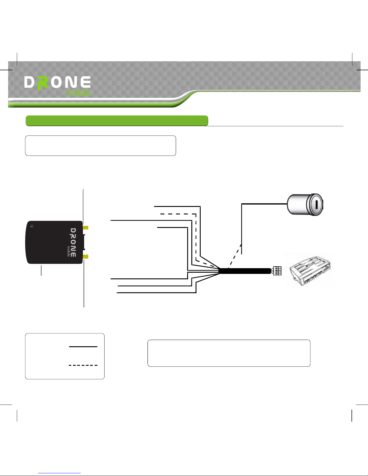
Introduction
Welcome to the DroneMobile DR-2000 installation manual. This manual is intended for experienced
installers only. We highly recommend that you contact your local DroneMobile dealer and seek
professional installation. Call 888-820-3690 for more information.
Please observe the following guidelines when installing this system:
Programmable Output Connectors and timing settings can only be changed by the FT-•
OP500-KIT. Other options can be programmed by a Firstech compatible RF Kit.
Do not use the battery backup port on the CM5 or CM6 Series control modules to power the•
DR-2000. It does not provide enough current. Use a power supply that can support up to 2
amps of current draw. Please use a digital multimeter to test all wires.
Drone 2 comes with the Type 2-Data Harness. The Hardwire Harness and External Antennas are•
available for an additional cost.
A Firstech remote start system MUST be installed to utilize all DroneMobile features. DroneMobile•
may be used with an aftermarket remote start but the Hardwire harness is required.
When using Type 1 installation and an RF Kit, you must program those remotes to the Drone.•
Please refer to the remote user manual for instructions.
Do not install under metal panels as that will hinder GPS and/or cellular signal.•
Once installation is complete do not connect the plugs into the DR-2000. First activate and
register your DroneMobile online at https://live.dronemobile.com/login. Click on “New Dealer
Registration” or login with your Dealer Account. Activate and wait for the SIM status to change to
“Active.” DroneMobile carries a 1 year manufacturer’s warranty.
Firstech, LLC. does not condone
or recommend installing DR-2000
on a vehicle with a fuel or ignition
interrupt. Doing so may result in
damage to the vehicle and/or injury
to driver.
Firstech, LLC. will not assume any
responsibility for improper use
and/or installation. For Terms
and Conditions refer to www.
dronemobile.com/usersmanuals
Introduction and Notices

These installation steps are very important. Please follow them carefully when
installing your first and every DroneMobile system. The Drone’s SIM MUST be
activated prior to powering on the DR-2000.
STEP 1: Install DroneMobile (and alarm/remote start system if applicable). Leave harnesses unplugged
from DR-2000.
STEP 2: Go to https://live.dronemobile.com/login and click on “New Dealer Registration.” If you
already have an account, login with your Dealer account information.
STEP 3: Register the Drone unit using the 20 digit serial number. (Click on “New Dealer Registration”
if this is your first time registering a Drone unit.) “Activating the SIM” window will open.
STEP 4: Once the “Activating the SIM” window closes and the status changes to “Active” you may
now plug the harnesses into the DR-2000.
STEP 5: Wait for the unit to achieve cell lock (blue LED flashes slowly)
STEP 6: Once the unit has achieved cell lock, power cycle (unplug) the unit once more. Wait for the
unit to achieve cell lock then you may proceed to the “Settings” page.
STEP 7: Complete the “Hardware Installation,” “Controller Settings,” and “Alert Notifications” sections.
Click “Save”to save your settings.
STEP 8: Once you are on the “Controls”page, test all of the features including GPS tracking to verify
that the unit is fully functional before releasing the vehicle.
STEP 9: Give your customer the 20 digit serial number and Quick Start Card and have them register
the unit in their name by going to https://live.dronemobile.com/login and clicking on “New
User Registration.” If they currently have an account, have them log in and “Manage Account”
> “Add/Remove Vehicle(s).”
Installation Overview
3 | Copyright 2012 Firstech, LLC.
Failure to select correct install type will require a call to tech support to reset.
If you log out of this session or your session expires, you have until midnight
the day of activation to log back in. Once the end user registers their Drone,
you will no longer have access to the unit.
TM DR-2000 Install Guide

Wiring Diagrams
DroneMobile can be installed using installation Type 1-Standalone, Type 2-Data, and Type 3-Hardwire
Required
Optional
Follow Type 1 when using DroneMobile as a standalone system
and GPS tracking device. Firstech RF kit is optional.
Copyright 2012 Firstech, LLC. | 4
Type 1 - Standalone With RF Kit and Bypass
Red: (+) 12 Volt Constant
Yellow:
White:
Blue/Black: (-) Programmable Output 1
Brown: (-) Programmable Alarm Trigger Input
Green: (+) Ignition Input
Black: (-) Ground Input
Blue(Thin)
Blue: (-) Programmable Output 2
Orange: (-) Programmable Output 3
Optional External Cellular Antenna Port
Optional External GPS Antenna Port
Yellow:
White:
Black:
Black:
Orange:
GPS
GSM
TM
Reset Button
6 Pin Antenna Port
RS232 Data Port
4 Pin Antenna Port
12V+ Constant
12V+ Ignition
Chassis Ground
See Option 2-05
See Special Option Group 2
Bypass Module
TM
Do Not Use Both Antenna
Ports At The Same Time
See Special Option Group 2
DR-2000 Install Guide

TM
Wiring Diagrams
Required
Optional
DR-2000 Compatible
Firstech Control Module
Follow Type 2 when using DroneMobile with a
compatible Firstech Control Module
5 | Copyright 2012 Firstech, LLC.
The Green Ignition Wire is only used if the
contol module does not support 2 Way Data or
Ignition signal through data.
Type 2 - Data
Red: (+) 12 Volt Constant
Black:
N/A
N/A
N/A
Green: (+) Ignition Input
Black: (-) Ground Input
N/A
N/A
N/A
12V+ Ignition
Yellow:
White:
Black:
To RS232 Data Port On
Control Module
Optional External Cellular Antenna Port
Optional External GPS Antenna Port
GPS
GSM
TM
Reset Button
DR-2000 Install Guide

TM
Wiring Diagrams
Required
Optional
Compustar or
Aftermarket
Remote Start *
Follow Type 3 when connecting DroneMobile to a non-data
Firstech control module or aftermarket alarm and remote start
Copyright 2012 Firstech, LLC. | 6
Type 3 - Slave / Hardwire
6 Pin Antenna Port (Not Used)
RS232 Data Port (Not Used)
4 Pin Antenna Port (Not Used)
Red: (+) 12 Volt Constant
Yellow:
White:
Blue/Black: (-) Programmable Output 1
Brown: (-) Programmable Alarm Trigger Input
Green: (+) Ignition Input
Black: (-) Ground Input
Blue(Thin)
Blue: (-) Programmable Output 2
Orange: (-) Programmable Output 3
Optional External Cellular Antenna Port
Optional External GPS Antenna Port
Yellow:
White:
Black:
Black:
Orange:
GPS
GSM
TM
Reset Button
12V+ Constant
12V+ Ignition
Chassis Ground
*See Option 2-05
*See Special Option Group 2
DR-2000 Install Guide

TM
Details
Wiring Details
Data Harness (DR-HRN-2KDA Included In Box)
Green: (+) Ignition Input - Connect this wire to the vehicle’s ignition output. This wire should see
(+) 12V when the vehicle’s key is in the “on” position. This wire is not required in Type 2 installations
unless the Drone compatible Data Controller requires it.
RS232 Plug - This plug is intended to connect to the RS232 Data Port on CM5 or newer Firstech
compatible control modules. (Not compatible with LT Series) The control module must have the most
current firmware to be Type 2 compatible.
Type 1/3 Hardwire Harness (DR-HRN-2KHW)
Red: (+) 12 Volt Constant Input - This is the constant power for the DR-2000. It carries a 2 amp fuse
and must be connected to the vehicle’s constant (+) 12 Volt source.
Green: (+) Ignition Input - Connect this wire to the vehicle’s ignition output. This wire should see (+)
12V when the vehicle’s key is in the “on” position. This wire is required in Type 1 in order to program
the remotes.
Black: (-) Ground Input - Connect this wire to the vehicle’s chassis ground.
Blue/Black: (-) Programmable Output 1 - This wire provides a programmable negative (-) output
that can be programmed on the Drone’s Option Menu. Please see the Special Option Group 2 Menu
for details. At the default setting this wire acts as a door lock output. This wire is not available in Type
2 installations. You must wire a relay to provide a positive (+) output.
Blue: (-) Programmable Output 2 - This wire provides a programmable negative (-) output that can
be programmed on the Drone’s Option Menu. Please see the Special Option Group 2 Menu for
details. At default setting this wire acts as a door unlock output.
7 | Copyright 2012 Firstech, LLC.
DR-2000 Install Guide

TM
Wiring Details
Details
This wire is not available in Type 2 installations. You must wire a relay to provide a positive (+) output.
Orange: (-) Programmable Output 3 - This wire acts as a programmable negative (-) output for the
Drone. Please see the Special Option Group 2 Menu for details. At the default setting this wire will
send a negative start trigger output. Setting 2 changes this output to a negative parking light output.
Brown: (-) Programmable Auxiliary Trigger Input - See option 2-05. This wire acts as a
programmable negative input for the Drone. At default it will take a negative 5 pulse trigger. It can
be programmed to take a negative latched input. Upon trigger this wire will send an alarm triggered
notification to the web interface and user’s smartphone. Setting 3 changes this wire to a negative (-)
foot brake input. It will shut the remote starter down. This wire is not required in Type 2 installations.
4 Pin Antenna Port - This plug is intended to connect to a Firstech compatible antenna from a
compatible RF Kit. This is used if using Drone as a standalone piece as shown in Type 1 installations.
You can also use this port to connect the OP500 Option Programmer and set options. Do not use
both 4 Pin and 6 Pin Antenna Ports at the same time.
6 Pin Antenna Port - This plug is intended to connect to a Firstech compatible antenna from a
compatible RF Kit. This is used if using Drone as a standalone piece as shown in Type 1 installations.
You can also use this port to connect the OP500 Option Programmer and set options. Do not use
both 4 Pin and 6 Pin Antenna Ports at the same time.
RS232 Port - This port is used when connecting to a Drone compatible bypass module. The DR-2000
supports both ADS and Fortin bypass modules. (See Option 2-06) This port is typically used in Type 1
installations.
Copyright 2012 Firstech, LLC. | 8
DR-2000 Install Guide

TM
Activation and Placement
9 | Copyright 2012 Firstech, LLC.
Dealer Activation
STEP 1: The Drone’s SIM MUST be activated prior to powering on the DR-2000. Complete all
connections. Leave harness unplugged from DR-2000.
STEP 2: If you are a new DroneMobile dealer please visit https://live.dronemobile.com/login to
register your account. Click on “New Dealer Registration” and fill out the required information. Your
account will be used for any and all future DroneMobile activations so please do not lose the
login and password.
STEP 3: Complete this step before plugging the main harness into the DR-2000: Once logged in
you should be able to enter the 20 digit serial number and click “Submit.” “Activating the SIM” window
will open.
STEP 4: Once the “Activating the SIM” window closes and the status changes to “Active” you may
now plug the harnesses into the DR-2000.
STEP 5: Once the unit has achieved cell lock (blue LED flashes slowly), power cycle (unplug) the unit
once more. Wait for the unit to achieve cell lock then you may proceed to the “Settings” page. Please
see the Troubleshooting section for description of LEDs. Please complete all necessary tests of the DR-
2000.
Note: If you log out of this session or your session expires, you have until midnight the day
of activation to log back in. Once the end user registers their Drone, you will no longer have
access to the unit.
STEP 6: Complete the “Hardware Installation,” “Controller Settings,” and “Alert Notifications” sections.
Configure the other settings and click “Save”to save your settings. Installation type selection is not
required when using hardwire harness. (DR-HRN-2KHW)
DR-2000 Install Guide

TM
If you are not an authorized DroneMobile dealer and installing the product for the first time visit
https://live.dronemobile.com/login and click on “New User Registration.” Fill out the required
information and then click on “I Agree” to move to the Controller Settings. Installation type selection
is not required when using hardwire harness. (DR-HRN-2KHW)
Copyright 2012 Firstech, LLC. | 10
STEP 7: Once you are on the “Controls”page, test all of the features including GPS tracking to verify
that the unit is fully functional before releasing the vehicle.
STEP 8: Once complete, place the extra DR-2000 sticker on the Quick Start Card and give to the
customer. You may choose to setup their account or advise them to visit https://live.dronemobile.com/
login and click on “New User Registration.” If they already have a Drone account then they should log
in and access “Manage Account” > “Add/Remove Vehicle(s)” option.
Suggested Mounting Locations
We recommend mounting the DR-2000 beneath the seat or in the vehicle’s dash. The higher the
location the better the signal will be.
Activation and Placement
DR-2000 Install Guide

Remote Programming Routine
IMPORTANT: Any and all remotes must be coded to the Drone prior to
performing any and all operations. Also the parking light output from the
Drone must be connected to indicate the programming sequence.
STEP 1: Activate programming mode by manually turning the vehicle’s key
between the Ign On and Off (or the Acc & On positions) five times within
7 seconds. The vehicle’s parking lights will flash once with the successful
completion of this step. (Note: this step also places the Drone into Valet Mode)
STEP 2: Within a 2 second period after the 5th ignition cycle tap Button I on two way remotes or
the Lock button on one-way remotes for a half second. The parking lights will flash once to confirm
the transmitter has been coded. Repeat for additional remotes, up to three. Exiting Programming:
Programming is a timed sequence. After 2 seconds the parking lights will flash twice signaling the end
of programming mode.
Programming Multiple Remotes: After the confirmation flash given in STEP 2, code additional
remotes by tapping Button I on two way remotes or the Lock button on one way remotes. The parking
lights will flash once confirming each additional remote. All systems can recognize up to three
remotes.
Note: If you do not program any remotes and enter this sequence it will put the system into Valet
Mode. Only the keyless entry will work in Valet Mode. To exit Valet Mode just program remote(s).
Valet Mode
TM
11 | Copyright 2012 Firstech, LLC.
The DR-2000 has Valet Mode. This prevents the vehicle from remote starting, arming the factory
style alarm, and flashing any parking lights. To exit valet mode tap the lock and trunk buttons on
the remote, reprogram the remotes, -or- uncheck the Valet option on the Web interface and click
“Save.” If Valet is unchecked, check the box, hit “Save” and then uncheck and hit “Save” again. These
methods will take the DR-2000 out of Valet.
Programming
DR-2000 Install Guide

STEP 1: Foot brake must be connected if not supported by
the bypass module. See Option 2-05 for details.
STEP 2: Start the vehicle with the key. Allow time for the
engine to idle down.
STEP 3: Learn tach. While the vehicle is at idle, hold the
foot brake and activate the remote start function on the
remote control for 2.5 seconds. The parking lights will flash
once to indicate a good tach signal. The parking lights will
flash twice to indicate the tach did not learn. Two seconds
following the two flashes, the number of parking light flashes
will indicate the cause of the error:
Tachless Mode – (Automatic Transmission Vehicles Only)
Tachless sensing is an alternative engine sensing mode. It does not require a connection to the vehicle
other than the main ignition harness.
STEP 1: Change Option 1-06 to setting 2 – No tach sensing.
STEP 2: Process complete – there is no further programming required other than adjusting crank time
when necessary (see below).
Timed Crank Setting – Automatic Transmission Only
Option 1-06 setting 3 provides a timed 1.5 second crank for the remote start sequence. This option
just cranks the vehicle for 1.5 seconds and assumes remote start has completed. This option can be
used for GM and other vehicles with built in anti-grind systems.
Number
of Parking
Light Flashes
Tach Error
1Option 2-10 is not in
default setting 1
2 Key is in the off position
3Bad tach signal. Find a
different wire.
TM
Copyright 2012 Firstech, LLC. | 12
Programming
DR-2000 Install Guide
Engine Sensing
Tach Sensing
The default engine sensing mode is tach through a bypass module. There are new features that adjust
tach reading methods on option 1-06. IMPORTANT: The remotes must be coded prior to setting up
tach sensing.

TM
Programming
DR-2000 Install Guide
Using FT-EZGO with DR-2000
Installing The FT-EZGO
Warning: Use these instructions if installing DR-2000 and FT-EZGO WITHOUT a Firstech control
module.
Step 1: Set Option 2-09 to desired option.
Step 2: Connect the Black 6 Pin antenna plug from the DR-HRN-2KHW to the Black 6 Pin antenna
port on the ANT-RFID.
Step 3: If using a Firstech RF Kit, connect that antenna cable to the Blue 6 pin port on the ANT-RFID.
If connecting to a 4 Pin to 4 Pin antenna, use the included 6 Pin to 4 Pin adapter.
Step 4: Find a spot to mount your ANT-RFID on the windshield. This is recommended for optimum
range. For more specific mounting location information visit us at www.firstechonline.com under the
Authorized Tech section document titled: “FT-EZGO Recommended Mounting Locations.”
Step 5: Program your EZ100-R and additional RF Kit remotes to the DR-2000 (Maximum 3 Remotes
including EZ100-R).
You are now ready to test your FT-EZGO system.
Testing The FT-EZGO
Step 1: Turn the auto unlock feature by holding the button on the EZ100-R for at least 8 seconds.
You will get one parking light flash and/or siren chirp. Hold the button again for at least 8 seconds
and you will get two parking light flashes and/or chirps showing that the auto unlock feature is off.
Step 2: Arm/Lock the vehicle and wait at least 15 seconds.
Step 3: Walk up to the vehicle and it will automatically unlock/disarm. If Setting 2 is selected, walk
away and the vehicle should lock/arm.
13 | Copyright 2012 Firstech, LLC.

TM
Option Tables
Option Group 1
Feature Default
Setting - I
Optional
Setting - II
Optional
Setting - III
Optional
Setting - IV
*1-01 *Unlock before, Lock
after, starting Off On
Lock After
Remote Start
Only
Lock After
Shutdown
Only
*1-02 *Double pulse unlock Off On
1-03 Diesel Timer Wire (Bypass
Module)
3~99sec
(10sec
Default)
1-04
Timer Start, or,
Minimum Interval
Between Starts
3 Hour (4 minute
runtime, double
for Diesel)
1.5 Hour(4
minute runtime,
double for
Diesel)
1-05 Remote Start Runtime 15 Min 25 Min 45 Min 3 Min
1-06 Engine Sensing Tach (Bypass
Module) Tachless Mode
No Connection
– 1.5 Sec. Crank
(Automatic
Trans. Only)
1-07 Timer Mode Off On
*1-08 *Installation Mode Slave Unit
Standalone
Unit With
Bypass
* Options Available With
1-08 Set to Default
Programming
DR-2000 Install Guide
Copyright 2012 Firstech, LLC. | 14

TM
Option Tables
Option Group 2
Feature Default
Setting - I
Optional
Setting - II
Optional
Setting - III
Optional
Setting - IV
*2-01 *Factory Style Alarm Off On
2-02 Soft Disarm Off On
2-03 Aux 1 output 0.5sec Latch 20 sec Program
2-04 Aux 2 output 0.5sec Latch 60 sec Program
*2-05 *Auxiliary Input
(Brown Wire)
(-) Alarm
Trigger When
Pulsed 5
Times
(-) Alarm
Trigger With
Latched
(-) Foot Brake
Input
2-06 Bypass Through RS232
Port ADS 2 Way Fortin 2 Way
*2-07 *Low Battery Warning Off On
2-08 Triple Pulse Trigger For
Remote Start On Off
2-09 FT-EZGO Mode FT-EZGO
Unlock
FT-EZGO
Lock and
Unlock
FT-EZGO
Unlock for
FTX
Programming
DR-2000 Install Guide
Note: Changing Option 1-08 to Setting 2 will unlock all options on the OP500
15 | Copyright 2012 Firstech, LLC.

TM
Option Table
Special Option Group 1
Feature Setting Value (Seconds)
1Diesel Timer - DISL 3 ~ 99
2AUX1 output time 1 ~ 100
3AUX2 output time 1 ~ 100
Special Option Group 2
Feature Setting and OP500 Value
Programmable
Output Connector 0 - Default Setting *1~13 – Optional Settings
1POC #1 (-) Lock (Blue/Black) Trunk - [1] Ignition - [2]
Accessory - [3] Starter - [4]
Start Trigger - [5] Aux 1 - [6]
Aux 2 - [7] Horn Honk - [8]
GWR - [9] GWA - [10]
Lock - [11] Unlock - [12]
Parking Light - [13]
2POC #2 (-) Unlock (Blue)
3POC #3
1-08: Default (-) Start
Trigger (Orange)
1-08 Setting 2: (-)
Parking Light (Orange)
Programming
DR-2000 Install Guide
* POC Options 2, 3, 4, 9, and 10 are not available when Option 1-08 is on Default
setting 1.
Copyright 2012 Firstech, LLC. | 16

TM
Option Descriptions
1-01 Unlock Before, Lock After Starting. Lock After Remote Start - If enabled, this option will
make the system unlock the doors before remote starting, start the vehicle, then lock the
doors after the vehicle starts. It will then lock the doors again if the remote start run time
expires and the vehicle shuts down. This feature is for vehicles that have factory alarms that
need to be disarmed before remote starting.
1-02 Double Pulse Unlock - If enabled, this option will cause the system to double pulse the
unlock output. This option is used on a majority of Toyota vehicles. The first unlock pulse
disarms the alarm, and the second pulse unlocks the doors.
1-03 Diesel Timer – Use this option for wait to start. You can use setting 2 for a default wait to
start of 10 seconds, otherwise, you can adjust the time with your OP500 Programmer.
1-04 Timer Start or Interval Between Starts - This option dictates the time interval when the
control module will remote start.
Default 1: Will start and run for 4 minutes every 3 hours until the vehicle is remote started
or started by key.
Option 2: Will start and run for 4 minutes every 1.5 hours until the vehicle is remote started
or started by key.
1-05 Remote Start Runtime - This option gives you four different settings for the remote start run
time. The available options are 15, 25, 45, and 3 minutes.
1-06 Engine Sensing – This option selects the method in which the Drone will detect if the
vehicle’s motor is running. At default, it will look for that status through the bypass module.
Option 2 will monitor the vehicle’s battery and option three will crank for 1.5 seconds.
Programming
DR-2000 Install Guide
17 | Copyright 2012 Firstech, LLC.

TM
1-07 Timer Mode - This option enables the user to operate Timer Start (see option 1-04).
Remember that the user must still activate Timer mode using the remote (see the user
manual for that remote for instructions).
1-08 Installation Mode - This option is used to set the DR-2000 to control a preinstalled
remote starter. The optional setting 2 changes the DR-2000 to work with a bypass module
and compatible RF Kit to start the vehicle. Not all options are available with default setting.
2-01 Factory Style Alarm - This option turns the Factory Style Alarm on or off. When this option is
combined with an interface module, it will monitor input triggers and will provide horn
output if programmed as one of the POCs. In Type 3 installations the Drone will only
monitor the Brown Wire.
2-02 Soft Disarm - When a vehicle has a factory alarm, and the Firstech alarm is triggered, you
may have both alarms triggered at the same time. In the default setting, silencing the
Firstech system will not send the disarm pulse to the factory system, therefore requiring the
user to first silence the Firstech system and then unlock and disarm to silence the factory
system. Setting 2 sends the disarm and 5 seconds later sends the rearm pulse.
2-03 Aux 1 Output - This option determines the duration of the auxiliary 1 output. Setting IV
allows the output duration to be set for a specific length of time.
2-04 Aux 2 Output - This option determines the duration of the auxiliary 2 output. Setting IV
allows the output duration to be set for a specific length of time.
2-05 Auxiliary Input (Brown Wire) - This option controls the input on the brown wire. At default
this wire will look for 5 ground pulses. The optional setting 2 looks for a constant ground
trigger and option 3 looks for a ground foot brake input. This is to shut the remote start
down in the event it is not covered by the bypass module.
2-06 Bypass Brand Through RS232 Port – Default setting allows for compatibility with ADS
Idatalink modules. Setting 2 changes compatibility to Fortin bypass modules.
Programming
DR-2000 Install Guide
Copyright 2012 Firstech, LLC. | 18

TM
2-07 Low Battery Warning - This option is off. When the system is
armed and this feature is programmed, Drone will monitor the voltage of the vehicle’s
battery at its connection point. When the battery voltage drops to or below 11.3 volts the
Drone will send a Low Battery Notification and page to the 2 way. The remote will beep
several times for 5 seconds, every 50 seconds, 3 times and flash the battery indicator on the
remote. When you query the remote or unlock/disarm the system the remote will display the
voltage of the vehicle’s battery. In Type 2 installations, this option must also be turned on
the remote start control module.
2-08 Triple Pulse Trigger for Remote Start - This option will change the behavior of the
Programmable Outputs if set to 5. It will provide a triple pulse output for triggering the
remote starter.
2-09 FT-EZGO Mode - This option is NOT used if you are using a Firstech control module. At
default, the FT-EZGO will unlock the doors when you approach your vehicle. Setting 2 will
lock your doors when you walk away. It will also unlock the doors when you approach
your vehicle. Setting 3 is the same as Setting 1 however will keep your FT-EZGO antenna
awake at all times and prevent any unlocking delays. Setting 3 will increase the draw on
your vehicle’s battery.
IMPORTANT: The OP500 is required to change settings in Special Option Groups 1 and 2.
Special Option Group 1
1 Diesel Timer – Option 1-03 must first be set to setting 2. This special option allows a
specific wait to start time (in seconds) to be programmed. This prevents the need for a timer
relay and eliminates a connection to the “wait to start” wire.
2 Aux 1 Output Timing – Option 2-03 must first be set to setting 4. This special option allows
a specific output duration for Aux 1 to be programmed.
Programming
DR-2000 Install Guide
19 | Copyright 2012 Firstech, LLC.
Table of contents
Languages: