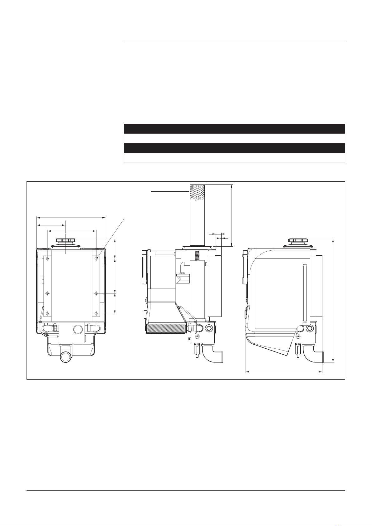
1. Allow a minimum space of 280 mm above the Hydrapak ller cap to
allow removal of the lter element when servicing.
2. When retting ller cap, only tighten by hand. Do not use excessive
force as this will cause the tank to distort.
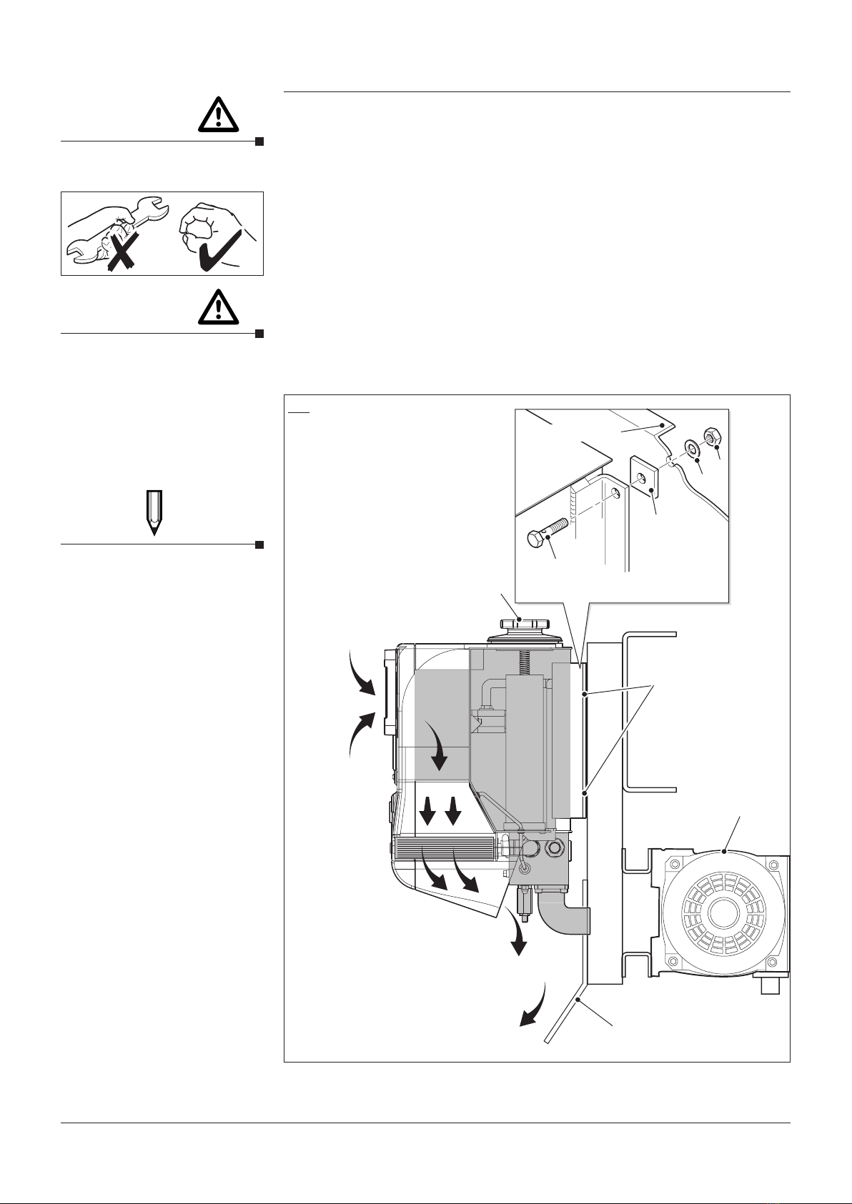
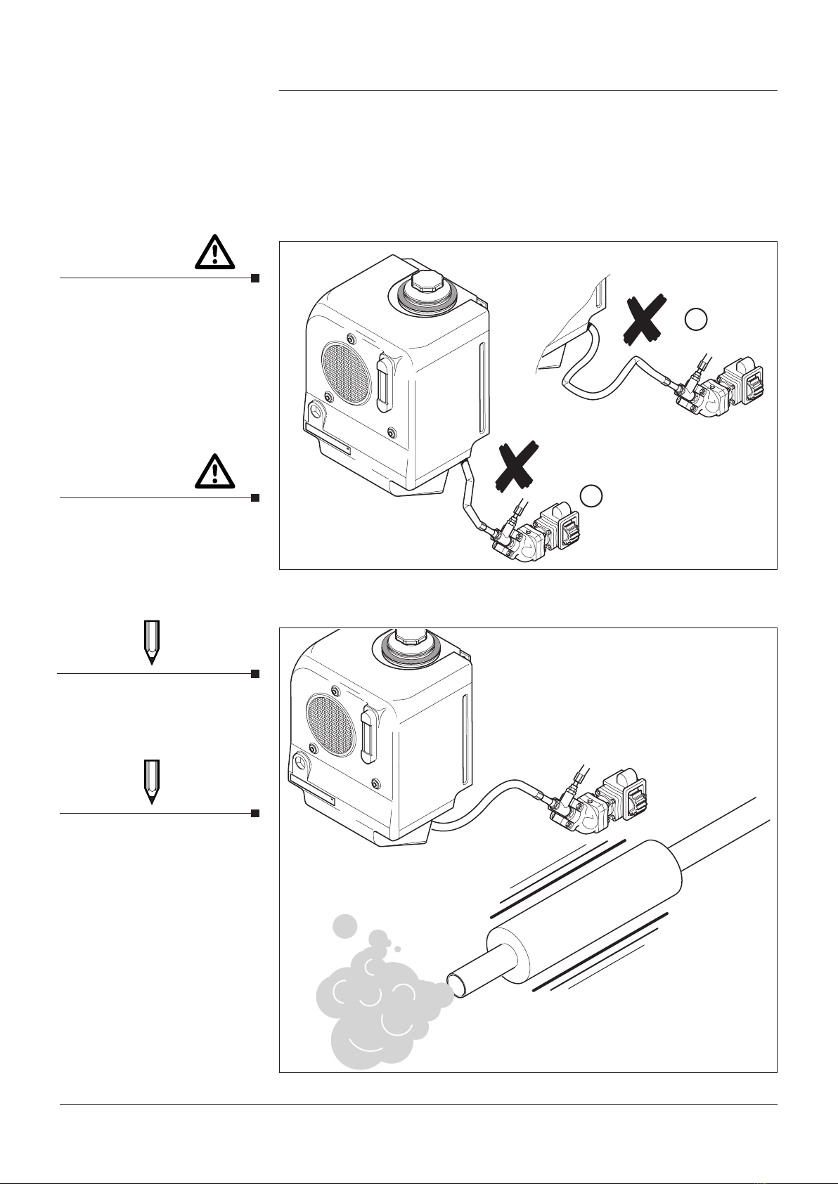
3. During installation it is important to make sure that the air inlet and
outlet ducts (shown below Fig 2) are not obstructed,
allowing a free ow of air for maximum cooling.
4. Typically ISO VG46 hydraulic oil will be suitable but the correct
viscosity for the hydraulic pump and motor (see manufacturers
instructions) will also suce for the Hydrapak. Ensure that the oil
level coincides approximately with the mid point of the sight glass.
Run the unit for 1 minute then top up the oil level if necessary.
5. When the Hydrapak is sharing the same mounting uprights with a
compressor it is recommended that a deector plate is installed to
divert the hot air discharged away from the compressor. See Fig 2.
Installation
KEY
1. Chassis Frame
2. M12 Bolt
3. Anti-vibration Pad
4. M12 Washer
5. M12 Nut
6. Filler Cap
7. Typical Compressor Installation
8. Deector Plate
Fig. 2 Airow direction incorporating typical compressor installation.
1
AIR INLET
6
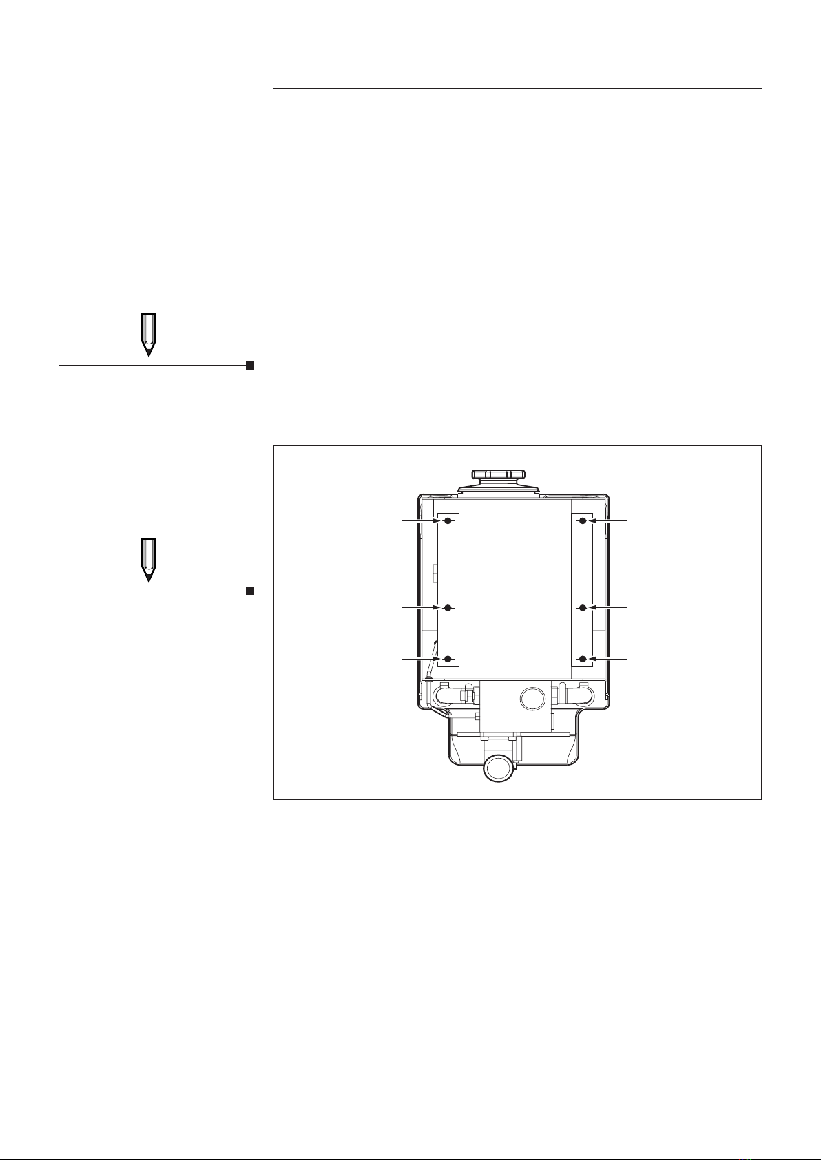
Mounting Points
7
8
HOT AIR OUT
2
3
4
5
Do not use excessive force
when tightening the Filler Cap.
CAUTION
Do not distort tank when
tting, ensuring tank is
secured using Anti-Vibration
pads as illustrated.
NOTE
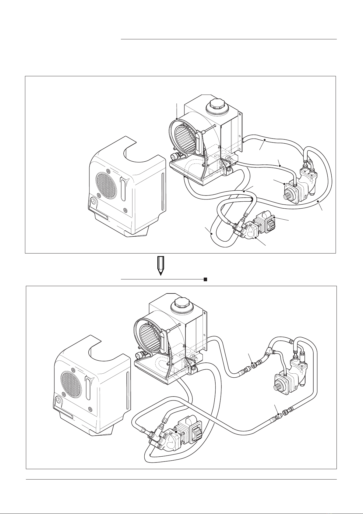
When the Hydrapak is to be
used on cryogenic’s, specialist
hydraulic oils are used. The
Motor supply hose should be
changed accordingly.
See page 19 & 20 for correct
part number.
CAUTION
Page 7
4991015005 Date:02/18 Hydrapak Installation, Operating & Maintenance Manual