Drytac JetMounter JM63 Fuzion XD User manual

JetMounter™ JM63 Fuzion XD
Rev February 2017
Operator’s Manual
The JM63 Fuzion XD is a heavy-duty, wide-format roller laminator with a heat assist top roller. Excellent for
laminating vehicle wraps, creating window decals and mounting graphics to substrates, it is ideal for shops
wanting to add roll-to-roll laminating capabilities at a lower price point. Standard features include heavy-
duty metal construction, large diameter non-stick silicone rollers, variable speed control, fold down front
table, built-in flip open storage compartments, top and bottom auto-grip supply shafts with brake tension
control on operator side, top auto-grip take-up shafts with adjustable clutch speed, single mechanical
height/pressure adjustment, interchangeable 110V or 220V electrical configuration, and photocell safety
protection.
WWW.DRYTAC.COM USA 800.280.6013 CANADA 800.353.2883

Overview .................................................................................................................................................................... 1
Warranty..................................................................................................................................................................... 2
Registration Information ............................................................................................................................................. 3
Important Safety Information ..................................................................................................................................... 4
Safety Symbols.................................................................................................................................................................4
Safety Features ................................................................................................................................................................6
Setup Procedures ....................................................................................................................................................... 7
Installation and Training Service......................................................................................................................................7
Unpacking and Installation ..............................................................................................................................................7
Power Supply...................................................................................................................................................................7
Parts Identification...........................................................................................................................................................8
Setting Roller Pressure ..................................................................................................................................................11
Adjusting Supply and Take-up Shaft Tensions ..............................................................................................................12
Mounting Applications.............................................................................................................................................. 13
Selecting Mounting Board and Adhesive......................................................................................................................13
Pre-Coating Mounting Board ........................................................................................................................................13
Mounting Graphics to Pre-Coated Boards....................................................................................................................14
Laminating Applications............................................................................................................................................ 16
Selecting Pressure Sensitive Overlaminating Film.........................................................................................................16
Laminating Single Unmounted Image ...........................................................................................................................16
Laminating Single Mounted Image ...............................................................................................................................17
Laminating Multiple Mounted Images ..........................................................................................................................18
Using a Leader Board ....................................................................................................................................................19
Carrier Boards and Preparing Mounting Board ............................................................................................................19
Care & Maintenance ................................................................................................................................................. 20
Roller Alignment Instructions.................................................................................................................................... 21
JetMounter JM63 Fuzion XD Operation Sequence ..................................................................................................23
JetMounter JM63 Fuzion XD Schematic................................................................................................................... 24
Contents
Operator’s Manual
WWW.DRYTAC.COM USA 800.280.6013 CANADA 800.353.2883

1
Overview
Operator’s Manual
JM63 FUZION XD Technical Specifications
Max Laminating Width 63” (1600mm)
Roller Diameter 4.7” (120mm)
Roller Construction Steel with High-Release Silicone Covering
Width 81.5” (2070mm)
Depth 28” (711mm)
Height 50.5” (1282mm)
Weight 752 lbs (341 kg)
Max Board Thickness 1” (25mm)
Max Material Roll Diameter 10” (254mm)
Electrical Requirements Dual Voltage: 110V, 8A or
Single Phase: 220V, 13A, 50/60Hz***
Speed Range 1 - 20 fpm (0.5 - 6 mpm)
Roll Core Size 3” (76mm)
Packaged for Shipment
Width 85” (2159mm)
Depth 34” (864mm)
Height 56” (1422mm)
Weight 875 lbs (397 kg)
Thank you for purchasing a Drytac®JetMounter™ JM63 Fuzion XD. The information contained in this Operator’s
Manual will explain the basic methods of mounting and laminating with this easy-to-use roller laminator.
The Infeed/Outfeed Table height of the JM63 Fuzion XD is 35.25” (895mm).
*** A power cord is provided for a standard 110V circuit. If a 220V circuit is needed, the customer is responsible for providing the
proper power cord and outlet to meet electrical requirements.

2
Warranty
Operator’s Manual
Every Drytac machine is designed and manufactured to provide years of dependable service. To achieve the best
results, the machine should be set up and operated in accordance with the instructions provided in its corresponding
Operator’s Manual.
Our equipment warranty covers parts for twelve (12) months and labor for three (3) months from the date of
purchase. During the first three months of the warranty period, Drytac or its dealer will arrange for the machine to be
repaired, replaced or refunded at Drytac’s discretion (excluding shipping and travel costs). Rollers are guaranteed
against manufacturing defects for three (3) months.
Return your warranty card to Drytac as soon as possible. By doing so, we will be able to more efficiently address your
concerns in the unlikely event that you encounter an issue. You will find a section in the Operator’s Manual for recording
this important information and for noting any future parts or service requests.
Normal wear and tear, damage to the rollers, and damage due to abuse, improper operation or installation is not
covered by this warranty. Conditions that will void the warranty include, but are not limited to:
• Failure to follow the instructions contained in the Operator’s Manual
• Unauthorized changes or modifications to the equipment or the stand
• Misuse of the equipment for purposes other than specified in the Operator’s Manual
Drytac will not be held responsible for any damage or consequential damage caused by the equipment. After the
warranty period has expired, Drytac will provide all reasonable product assistance and support to resolve any problems
that may arise.
Before calling the Drytac Technical Services department, note the Registration Information for your machine and have it
available for reference.

3
Registration Information
Operator’s Manual
USA
Drytac Corporation
5601 Eastport Boulevard
Richmond, VA 23231
+1 800-280-6013
+1 804-222-3094
CANADA
Drytac Canada, Inc.
105 Nuggett Court
Brampton, Ontario L6T 5A9
+1 800-353-2883
+1 905-660-1748
JetMounter™ JM63 Fuzion XD Registration Information
COMPANY NAME:
ADDRESS:
CITY, STATE, ZIP:
SERIAL #:
PURCHASE DATE:
WARRANTY CARD RETURN DATE: BY:

4
Important Safety Information
Operator’s Manual
Before operating the JetMounter™ JM63 Fuzion XD for the first time, read and understand the following safety-related
information. Failure to follow these procedures may result in serious personal injury and/or damage to the equipment
and materials being used.
Safety Symbols
Danger and/or warning symbols indicate imminently and/or potentially hazardous situations that, if not avoided, may
result in serious injury or death.

5
Important Safety Information
Operator’s Manual
The JetMounter™ JM63 Fuzion XD performs mounting and laminating applications by using two
rollers to apply uniform pressure to mounting adhesives and overlaminating films. The point where
the rollers touch these materials is called the “Nip”. This area creates a potential pinch hazard for
fingers or other objects. TO AVOID INJURY, ALWAYS KEEP YOUR FINGERS AWAY FROM THE
NIP AREA.
When using a large supply roll, be aware that a pinch hazard may exist between the top roller and
the supply shaft. When working from the rear of the machine, be aware of the pinch point (Nip) of
the contacting rollers and exercise extreme caution to avoid injury.
Exercise caution when lifting rolls of adhesive or laminate due to their weight. Obtain assistance to
avoid personal injury or damage to the equipment and materials.
No persons under the age of 16 should be allowed to operate the equipment.
DO NOT operate the equipment while under the influence of alcohol, prescription drugs or any other substance that
could impair your judgment or reaction time.
Remove any jewelry such as rings, bracelets and necklaces prior to operating the equipment. Keep loose clothing,
neckties, artificial fingernails, long hair, and anything else that might easily be drawn into the rollers away from the
machine.
Always work at a slow speed until you become familiar with the equipment.
Power “Off” the machine when loading rolls of adhesive or laminate, cleaning the rollers, or performing other activities
that require close proximity of fingers to the Nip area. Doing so will prevent the machine’s rollers from inadvertently
turning. During machine operation, keep fingers away from the Nip area.
Always disconnect the equipment from the power supply before removing any panels for
service.

6
Important Safety Information
Operator’s Manual
Safety Features
The following safety features are designed to offer a reasonable measure of protection against injury while maintaining
an operator-friendly machine. Please do not attempt to disable or alter their functionality in any way. Any modifications
will void the warranty and may pose a serious risk to the operator. If any malfunction occurs, stop using the
machine immediately and contact the Drytac Technical Services department.
The JM63 Fuzion XD has electric eyes or photocells installed in front of the Nip area for safety. When interrupted,
they will stop the rollers immediately, a photocell status LED on the Control Panel will light up, and a buzzer will sound
as a warning to indicate that an object is breaking the photocell circuit. Be particularly cautious when operating the
equipment with the Foot Pedal as the rollers WILL NOT STOP when the photocells are interrupted. An audible alarm
will sound, but the rollers will continue to turn at a reduced speed.
Prior to operating the equipment, always check that the photocells and buzzer are working properly. Use a piece of
cardboard to block the photocells to confirm that the alarm sounds and the rollers stop.
The JM63 Fuzion XD is also equipped with two red Emergency Stop Buttons, located on the top of both the left and
right end cases. The Emergency Stop Buttons will stop the machine immediately, shutting off power to the Control
Panel. The machine can also be stopped by lifting your foot off the Foot Pedal, turning the Speed Control Knob to zero
(0), turning off the Power Button on the Control Panel, or turning off the main Power Switch on the back of the left
end case. If there is a “No Power” condition, check to see if the Emergency Stop Buttons are depressed before further
troubleshooting.

7
Setup Procedures
Operator’s Manual
Installation and Training Service
Installation and training is available for the JetMounter™ JM63 Fuzion XD. This service ensures that the machine is set
up properly and the individual operating it is trained on the various applications the machine can perform. If you have
operational questions, contact the dealer you purchased the machine from or the Drytac Technical Services department
for installation/training details or to schedule this service.
Unpacking and Installation
Upon receipt of your new JM63 Fuzion XD, inspect the shipping crate carefully for signs of physical damage or
mishandling. Before signing for the shipment, there are two rough handling indicators that should be inspected. If
either of these devices is “tripped”, note it on the receiving paperwork. Report any damage to the shipping company
immediately and contact the Drytac Customer Service department if replacement parts are needed. If there is no
apparent damage, proceed with unpacking.
It is recommended that two people unpack the equipment to avoid personal injury or damage
to the equipment. Handle with care. Follow the steps described in the uncrating instructions
(which are attached to the shipping crate) to safely remove the equipment from its packaging. If
the uncrating instructions are missing, contact the Drytac Technical Services department before
attempting to unpack or install the equipment.
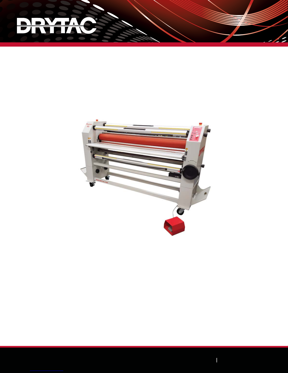
The JM63 Fuzion XD is fully assembled on a stand for easy positioning. When moving the
machine, there should be one person on either side to help guide it. To eliminate the possibility
of it tipping over onto either person, push the machine from the ends only. Do not push the
machine from the front or back.
Select a clean, well-lighted work area that allows access to both the front and back of the machine. To ensure adequate
accessibility and safety, position the machine so that there is at least 3’ (0.9m) of space from the front and back beyond
the largest piece of material to be used.
For example, if using a 4’ x 8’ (1.2m x 2.4m) foam board, a minimum of 11’ (3.4m) of space in front and 11’ (3.4m) of
space in back of the machine would be needed. Always consider this rule prior to starting an application.
Power Supply
The JM63 Fuzion XD can operate on either a 110 or 220 volt power supply. Set the proper voltage BEFORE plugging
the machine in for the first time. On the back of the left end case, there is a switch under a clear plastic cover that
can be adjusted to the specific voltage required. If you have questions regarding the machine’s electrical requirements,
contact a qualified electrician prior to powering “On” the machine. Confirm that the voltage supplied at the outlet
corresponds with the voltage marked on the plate attached to the machine. Do not rely on the power cord or outlet
configuration to determine the correct power supply voltage. It takes 10-15 minutes (at 220 volts) and 30-40 minutes
(at 110 volts) for the top roller to reach approximately 110°F (43°C). After processing is completed each day, turn the
main Power Switch located on the back of the left end case near the power cord entry to the “Off” position.

Parts Identification
On/Off Switch: A rocker switch located on the back of the left end case of the machine near the power cord entry.
Used to power the machine on and off. The switch should be in the “Off” position when loading/unloading adhesive or
laminate, cleaning the rollers, or performing other activities that require close proximity of your fingers to the Nip area.
The switch should also be turned to the “Off” position after processing is completed each day.
8
Setup Procedures
Operator’s Manual
Equipment Parts
Take-ups & Unwinds Rollers & Idlers Operator Controls
ATop Front Take-up FTop Heat Assist Roller JControl Panel
BTop Rear Unwind/Supply GBottom Cold Roller (behind table) KPrint Guide
CBottom Front Unwind/Supply HTop Idler LInfeed Table
DBottom Rear Take-up IBottom Idler MOutfeed Table (behind rollers)
NHeight Wheel
OFoot Pedal
PBrakes
QEmergency Stop Button
A
B
D
C
F
H
I
J
N
K
L
P
O
Q

9
Setup Procedures
Operator’s Manual
Parts Identification cont.
Control Panel:A panel located on the upper angled surface of the right end
case used to control and monitor various functions of the machine.
Power Button: A button located in the lower left corner of the Control Panel
that when pressed activates power to the machine. When an Emergency
Stop Button is pressed and the reason for it being activated is corrected, the
Emergency Stop Button must be reactivated and the Power Button pressed to
proceed. If the machine’s shutdown is caused by a thermal overload condition,
allow the circuit breaker on the back of the machine to cool for approximately
20-30 seconds. Then, reset the breaker and power up the machine by pressing
the Power Button.
Roller Button: A button located on the Control Panel above the F/R Button.
Used to activate the motor that turns the bottom roller. An ON/OFF status
LED to the right of the button will light to show when power is supplied to the
motor. When the photocell circuit is interrupted due to an obstruction, the
Roller Button must be reactivated before resuming operation. The photocell
(PC) status LED to the right of the Power Button will light when this interruption
occurs.
F/R Button: A button located on the Control Panel above the Power Button. Used to select the direction of the bottom
roller. Press the button to change directions. A FWD/REV status LED to the right of the button will light to show which
direction (forward or reverse) has been selected. Ensure the roller has stopped before changing direction. To activate
the roller in reverse, depress the Foot Pedal. An audible alarm will sound, but the roller will continue to turn at a
reduced speed. When operating in reverse, the machine’s photocells will not be active.
Heat Button: A button located on the Control Panel above the Roller Button. Used to activate the heat assist
function. When the button is pressed, a temperature status display to the right of the up/down arrows will indicate the
temperature of the top roller. The heating rod begins to heat the roller to the designated temperature setting of 110°F
(43°C). A temperature scale LED to the right of the temperature status display indicates which temperature scale is
used. To change the temperature from Fahrenheit to Celsius, simultaneously press the up/down arrows and hold for 10
seconds. The temperature setting of 110°F (43°C) cannot be adjusted, but the readout may be higher since the sensor
reads actual roller temperature (which can be affected by numerous factors). When processing begins, heat is absorbed
into both the bottom roller and materials which causes the temperature to drop. The machine’s components are
designed to account for these variables, so readouts slightly above the set temperature should not cause concern. The
machine will not overheat. If the roller reaches 131°F (55°C), the heating system will shut down.
NOTE:
When the heating system is on, rollers should make contact and be moving with at least 20-40% pressure applied to
allow for maximum heat transfer and minimize roller distortion.

10
Setup Procedures
Operator’s Manual
Parts Identification cont.
Pressure & Height Display: A display located on the Control Panel above the Heat Button. The height of the Nip,
or space between the top and bottom rollers, is indicated from 0 to 25 millimeters on the display. Directly above the
height indicator are a series of LED lights, labeled in increments of 20 from 0 to 100, that indicate the percentage of
pressure applied to material in the Nip. The 0 LED remains illuminated at all times. When the top roller is lowered to
rest on the bottom roller (commonly referred to as the “Sweet Spot”), the 20 LED will light to indicate 20% pressure
has been exerted. Slowly rotate the Height Wheel clockwise to apply more pressure. As pressure is applied, the LED
lights will successively illuminate to show the percentage of pressure applied. For best results, set the pressure to 20%
or 40%. Drytac’s unique lift mechanism design allows for evenly controlled pressure over the entire contact area. To
prevent excessive pressure, premature failure of the machine, or damage to materials during processing, maximum
spring compression is restricted. To properly adjust pressure, refer to Setting Roller Pressure on page 11.
Speed Control Knob: A knob located on the Control Panel to the right of the Roller Button and F/R Button. Used to
control the speed of the motor-driven bottom roller. Rotate the knob to the right to increase the speed of the roller,
and rotate the knob to the left to decrease the speed. Speed control will not affect reverse speed or the speed of the
roller when the photocells are interrupted during Foot Pedal operation. The roller will move at a slow, steady speed (jog
mode) until the Foot Pedal is released. When the photocell obstruction is clear, the set speed will resume by pressing
the Roller Button.
Supply Shaft: A shaft used to support and feed a roll of material. Rubber cords lock the inside of the core and keep the
roll in place.
Take-up Shaft:A shaft used to remove and wind up the release liner from the roll of material being used. Rubber cords
lock the inside of the core and keep the roll in place.
When any shaft is installed, the slot end must be properly oriented to fit in the drive mechanism located on the right
end case. Consider this before lifting the loaded shaft into position. Once in position, insert keeper pins in the cups to
secure the shaft and prevent it from lifting from the cups. All shafts will fit into any position on the machine.
Height Wheel:A wheel located on the front of the right end case. Turn the wheel clockwise to raise the top roller and
counter-clockwise to lower it.
Foot Pedal: A foot switch positioned on the floor within easy reach of the operator. Used to activate the bottom roller
or bypass the photocells when webbing the machine. Be particularly cautious when operating the equipment with the
Foot Pedal as the rollers WILL NOT STOP when the photocells are interrupted. An audible alarm will sound, but the
rollers will continue to turn at a reduced speed.
Photocells: Electric eyes located on the left and right sides of the machine in front of the rollers. A safety feature used
to protect the operator from the Nip area between the rollers. When an object interrupts the photocells, the rollers will
stop turning and an alarm will sound. Once the object is removed from the Nip area and the Roller Button is depressed,
the rollers will start turning again at the speed set on the Speed Control Knob. When an object interrupts the photocells

11
Setup Procedures
Operator’s Manual
Parts Identification cont.
while the Foot Pedal depressed, the rollers will turn at a slower speed and an alarm will sound. Once the object is
removed from the Nip area, the alarm will stop and the roller will turn at a reduced speed until the Roller Button is
depressed.
Emergency Stop Button: Button located on the top of the left end case and on the top of the right end case. When
depressed, it stops the machine immediately and shuts off power to the Control Panel. To reset the Emergency Stop
Button, twist a 1/4 turn while simultaneously pulling up on the button.
Print Guide: Guide located on the top of the Infeed Table. Keeps the graphic flat during lamination.
Setting Roller Pressure
The Nip is the space between the top and bottom rollers. Both the Nip and pressure are controlled by the Height
Wheel, which raises and lowers the top roller. The roller height should be adjusted according to the material being
processed. For most applications, the normal operating range is between 20-40% pressure.
NOTE:
Applying too much pressure can create wrinkles and may damage the machine or the material being used. When the
machine is not in use, separate the rollers to prevent flat spots from developing.
Overlamination and Encapsulation
When processing thin graphics, the Nip should be closed and the pressure set to 40%.
Mounting
When mounting to substrates, the Nip should be set to the thickness of the substrate by turning the Height Wheel. The
leading edge of the substrate should be inserted and the pressure set according to the density of the substrate. Hard
substrates, such as Masonite® or Sintra®, should be set to 40-60% pressure. Soft substrates, such as foam board, should
be set to 20% pressure to avoid compression.
Narrow Graphics
Typically, less pressure is needed to correctly apply the graphic or laminate.
Checking Roller Parallelism
The roller alignment and pressure setting on the JM63 Fuzion XD is carefully set prior to shipping. A digital instrument
is used to calibrate the pressure from side to side within 0.2mm through various pressure ranges. A limiter mechanism
prevents the Height Wheel from turning when maximum pressure is achieved. Paper travel is a good indicator to
determine whether the setting has deviated and should be corrected. Paper travel greater than 0.12” (3mm) per 16’
(5m) of paper (within the 20-60% pressure range) requires adjustment in order to correct the deviance. Contact the
Drytac Technical Services department for assistance before attempting to make any adjustments.

12
Setup Procedures
Operator’s Manual
Adjusting Supply and Take-up Shaft Tensions
The JM63 Fuzion XD is equipped with a Take-up Shaft on the front of the machine that winds up the release liner
from the roll of adhesive or laminate during processing. Both the Take-up Shaft and Supply Shafts are equipped with
Brakes, which are important to adjust so that there is even tension on the adhesive or laminate during processing. Apply
enough resistance on the material to keep it firm and flat against the roller, but not so much that it stretches or distorts.
Additionally, it is critical to maintain even tension settings on both sides of the film to prevent curling. Turn the Brakes
clockwise to increase tension and counter-clockwise to reduce tension.
Supply Shaft Tension
When feeding adhesive or laminate into the rollers, it is important to maintain the feed at the same rate that the rollers
pull the material through the Nip. Slight resistance is usually all that is needed. Overtightening the Brakes is rarely the
solution to a tracking issue. When applying resistance to the material, “less is better”.
Take-up Shaft Tension
The release liner should be pulled away from the material at a steady rate that allows it to “lift” at a point just before
the material enters the Nip area. Keeping the correct tension will allow the release liner to be pulled away at the right
moment without excessive exposure of the material to dust and debris.

13
Mounting Applications
Operator’s Manual
Selecting Mounting Board and Adhesive
Selecting the proper mounting board/substrate is very important. Common materials that can be used are:
• Foam board - FomeCor®, GatorBoard®, HartBoard®, etc.
• Illustration board
• Rag board
• Medium Density Fiberboard (MDF)
• Corrugated plastic board - CoroPlast®
• Rigid plastic board - Sintra®, Styrene, etc.
• Tempered hardboard - Masonite®
Once the mounting board has been selected, determine whether to pre-coat it with adhesive or purchase pre-cut and
pre-coated boards. While the use of pre-cut, pre-coated boards will save time, coating your own mounting board is
more economical and allows for maximum flexibility in terms of sizing and substrate selection.
Pre-Coating Mounting Board
Pre-coating the mounting board means applying a mounting adhesive to one side of the board so that a graphic image
can be mounted to the board later. The use of a Leader Board is recommended for this process. For instructions, refer
to page 19.
1. Adjust the roller to the height of the substrate.
2. Load the roll of pressure sensitive adhesive (PSA) onto the Supply Shaft so that the material can be pulled
toward the operator from the underside of the roll with the adhesive side facing up (the release liner side
should be in contact with the roller as shown in the illustration below).
3. Pull the adhesive off of the roll so that about 4” (102mm) lies flat on the work table and is draped in front of
the rollers.

Mounting Applications
Operator’s Manual
14
Pre-Coating Mounting Board cont.
4. Lay the Leader Board on top of the exposed adhesive on the work table. Push the Leader Board and
adhesive into the Nip area (where the rollers make contact). When pushing the Leader Board into the
adhesive, make sure it is parallel to the rollers.
5. Position the first mounting board behind and against the Leader Board. Check for proper alignment and
feed through the rollers. Feed one board after another, as needed. Position the Leader Board behind the last
board to be coated so the adhesive can be cut from the roll. Trim the excess adhesive off of the board.
6. The mounting boards are now pre-coated with PSA, which is still protected by the release liner. The pre-
coated boards can be used for immediate mounting or stored for future use.
TIP:
When a graphic image is going to be laminated with a gloss overlaminating film, the use of very smooth substrates
with glossy surfaces (such as Masonite®) is preferred. This will minimize the effect of board imperfections (i.e.,
“orange peel”) in the finished product.
Mounting Graphics to Pre-Coated Boards
1. Adjust the roller to the height of the substrate.
2. Expose the adhesive on the board by folding back approximately 1” (25mm) of the release liner.
3. Using the folded-back release liner as a temporary support bridge, align the graphic image onto the board
and proceed to “tack” (stick or press down) the leading edge of the graphic onto the exposed adhesive.
4. Run a Leader Board of the same thickness as the mounting board through the rollers so that the back edge
of the Leader Board is at the Nip area of the machine.

Mounting Applications
Operator’s Manual
15
Mounting Graphics to Pre-Coated Boards cont.
5. Square the mounting board with the tacked graphic against the edge of the Leader Board and drape the
graphic over the top roller.
6. Run the mounting board/adhesive/graphic image through the rollers while simultaneously pulling the release
liner away from and off of the board.

Laminating Applications
Operator’s Manual
16
Selecting Pressure Sensitive Overlaminating Film
Select an appropriate pressure sensitive overlaminating film for the surface of the graphic image based on aesthetics
and the conditions under which it will be displayed. Drytac offers a wide variety of films to match your specific output
and application. Consult the Drytac Product Reference Guide for descriptions of available overlaminating films or visit
www.drytac.com.
To prevent adhesives from sticking to the rollers and to provide a reusable, standard working surface during lamination,
the use of a silicone-coated board (also known as a “Carrier Board”) is highly recommended. For instructions, refer to
page 19.
Laminating Single Unmounted Image
Before processing, make sure that the graphic image is clean and free of dust or specks of lint. An anti-static cloth or
anti-static wisk is recommended for cleaning the graphic prior to lamination.
1. Raise the top roller and insert the Carrier Board. Set roller pressure as previously described.
2. Pre-cut a sheet of overlaminating film from the roll. The sheet should be larger than the graphic image by
approximately 1” (25mm) on the bottom and each side and 2” (50mm) on the top.
3. Peel and fold back approximately 2” (50mm) of release liner from the top edge of the overlaminating film.
Tack the film on the Carrier Board by pressing the exposed section of film onto the leading edge of the
board.
4. Advance the Carrier Board into the machine using the Foot Pedal. Stop before the edge of the
overlaminating film reaches the rollers.

Laminating Applications
Operator’s Manual
17
Laminating Single Unmounted Image cont.
5. Lift up the remainder of the overlaminating film (which is still protected by the release liner) and slide the
graphic image face underneath it. Stop before it makes contact with the exposed part of the adhesive. It is
important to keep the film adhesive away from the graphic until the whole assembly is under pressure and
traveling through the machine.
6. Lay the overlaminating film over the top of the upper roller. While holding up the edge of the peeled back
release liner with one hand, start the rollers and apply the overlaminating film to the surface of the graphic.
Pull up and away on the release liner as your graphic travels through the machine. Ensure that the release
liner does not reach the point where the graphic makes contact with the top roller. Complete this step with a
consistent motion and do not stop until the entire graphic has passed through the rollers.
7. The laminated graphic can now be easily removed from the silicone-coated Carrier Board for trimming and
mounting.
Laminating Single Mounted Image
Before processing, make sure that the graphic image is clean and free of dust or specks of lint. An anti-static cloth or
anti-static wisk is recommended for cleaning the graphic prior to lamination.
1. Raise the top roller and insert the mounted graphic image into the roller Nip area. Adjust the roller pressure.
2. Pre-cut a sheet of overlaminating film from the roll. The sheet should be larger than the graphic image by
approximately 0.25” (6mm) on the bottom and and each side and 3” (75mm) longer on the top.
3. Peel and fold back approximately 2” (50mm) of release liner, exposing the adhesive of the overlaminating
film.
4. Tack approximately 1.5” (38mm) of the film to the Leader Board but not over the mounted graphic.

Operator’s Manual
18
Laminating Applications
Laminating Single Mounted Image cont.
5. Insert the Leader Board with the overlaminating film tacked to it into the Nip area. Advance the Leader
Board and the film through the Nip area until the upper roller securely pinches the film. The trailing edge of
the Leader Board should be at the pinch point of the rollers.
6. Lay the overlaminating film over the top of the upper roller. Ensure that the folded release liner is easily
accessible.
7. Slide the mounted graphic image into the Nip area and allow its edge to make contact with the edge of the
Leader Board.
8. While holding up the folded edge of the peeled back release liner with one hand, start the rollers and
apply the overlaminating film to the surface of the graphic image. Pull up and away on the release liner as
the graphic advances to ensure that the liner does not reach the Nip area. Use a consistent motion and do
not stop until the entire graphic has passed through the rollers. The laminated graphic can now be easily
removed from the silicone-coated Carrier Board for trimming and mounting.
9. Trim excess overlaminating film from the edges of the graphic.
Laminating Multiple Mounted Images
1. For higher volume jobs, select a roll of overlaminating film slightly wider than the mounted graphic images to
be laminated.
2. Install the overlaminating film on the Supply Shaft so that the material can be pulled toward the operator
from the bottom of the roll with the release liner side facing up.
3. Adjust the rollers for proper pressure.
4. Pull several inches of the overlaminating film off of the roll. Separate approximately 3-4” (76-102mm) of the
overlaminating film from its release liner and drape it onto the Infeed Table in front of the rollers. Attach the
release liner to the core on the Take-up Shaft.
Release liner
being removed
This manual suits for next models
1
Table of contents
Other Drytac Laminator manuals