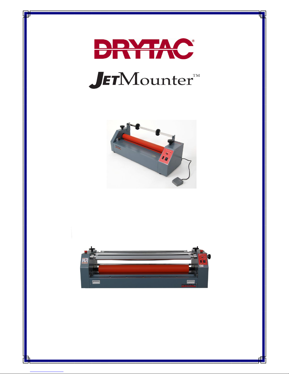
Drytac Jet Mounter JM18 User manual

COLD-MOUNT LAMINATOR SERIES
OPERATORS MANUAL
Models: JM18, JM26, JM34, JM44, JM44 SHA, JM54, JM54SHA
Manual Version 13-08-10

2
Copyright © 2006 Drytac Corporation / Revised © 2008 Drytac Corporation
All rights reserved. No part of this publication may be utilized or reproduced in a retrieval system, or
transmitted in any form or by any means; electronic, mechanical, photocopying, recording, or
otherwise,
without prior written permission from Drytac Corporation.

3
Welcome to the World of Drytac
Over the past three decades, Drytac has evolved into one of the world‟s most highly
regarded manufacturers of products for graphics finishing and display. Our core product line
consists of a wide range of pressure-sensitive, heatset and thermal overlaminating films. In
addition, we offer an extensive line of mounting adhesives, backing films, inkjet media,
finishing equipment, accessories, and banner stands.

4
Our “Start To Finish”strategy sums up Drytac‟s unique ability to manage all phases of the
customer experience: product quality and performance, manufacturing and distribution,
training and technical support and the industry‟s best customer service.
Jet Mounter™ Professional Quality Entry-Level Models
JM18, JM26, and JM34
These solid mid-size models deliver superior results for beginners and experienced users
alike. Easy to set up and operate, the JM18‟s and JM26‟s are widely used by photography
studios, picture framers, digital art studios and other creative shops, and our newest model
the JM34 are sure to also be as popular. Standard features include: all-steel construction,
variable speed electric drive, forward and reverse, foot pedal control, silicone rollers, photo-
electric safety stop and supply shaft.
Since all three models have many of the same features, consider references in this manual
pertaining to the JM26 to be applicable to the JM18 and the JM34.
Jet Mounter™ Wide Format Laminators
Drytac‟s Pressure-Sensitive Cold-Mount Models deliver economy and versatility for graphics
finishing. The JetMounter™motorized laminator series is engineered by Drytac to deliver a
combination of performance and value unequalled in the finishing industry. Compatible with
any pressure-sensitive overlaminating film, JetMounters are also ideal for permanently
mounting graphics onto cardstock, foam board, MDF or rigid PVC board.
All electric models include variable-speed electric drive, silicone rollers, all-steel
construction, forward and reverse, supply shaft, foot pedal and photo-electric safety stop.
The three heavy-duty wide-format models, (JM44, JM54, and the new JM63) are the
culmination of our three decades in the mounting and laminating business. Equipped with
the performance features our customers demand, JetMounter™wide format models are
unmatched for value.

5
Table of Contents
Overview..........................................................................................................................6
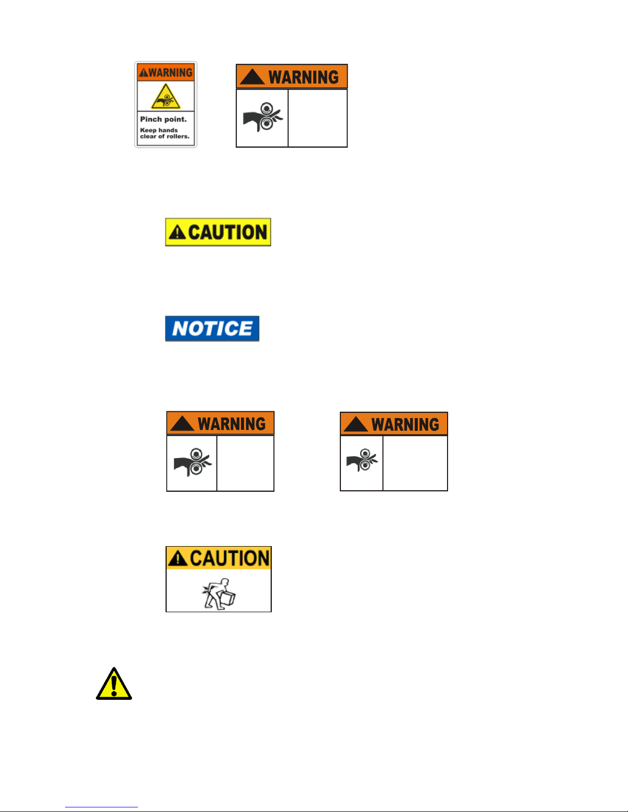
Important Safety Information .........................................................................................6
Specific Moving Instructions..................................................................................10
Unpacking and Installation.....................................................................................11
JM Components....................................................................................................12
Component Illustrations ........................................................................................14
Setting Roller Pressure..........................................................................................15
JM44SHA/JM54SHA Roller Pressure Adjustment .................................................16
Adjusting Shaft Tensions.......................................................................................17
Mounting With the JetMounter™Laminators
Mounting Board Selection......................................................................................18
Adhesive Selection................................................................................................18
Pre-coating the Mounting Board............................................................................18
Mounting a Graphic to a Pre-Coated Board...........................................................20
Laminating with the JetMounter™Laminators
Selecting a Laminate Film .....................................................................................21
Single Unmounted Graphic....................................................................................22
Single Mounted Graphic........................................................................................23
Laminating Multiple Mounted Images....................................................................24
Using a Leader Board............................................................................................25
Carrier Boards.......................................................................................................26
Preparing Mounting Boards...................................................................................26
Care and Maintenance....................................................................................................27
Service..................................................................................................................28
Technical Specifications........................................................................................29
Contact Information...............................................................................................30
Warranty..........................................................................................................................31
Appendix
Replacement Parts................................................................................................32
B Revision Functional Requirements.....................................................................33
JM44SHA/JM54SHA Nip Adjustment Procedure ......................................................34

6
Overview
Thank you for purchasing a Drytac JetMounter™Cold Mount Laminator. The information
contained in this manual will familiarize you with the basic methods of mounting and
laminating using this easy-to-use two roller laminator. This manual covers five JetMounter™
models:
Model
Width
Maximum Laminate
JM18
25.5” (64.8 cm)
18.25” (46.4 cm)
JM26
33.25” (84.5 cm)
26.25” (66.7 cm)
JM34
TBA
TBA
JM44/JM44SHA
52.75” (134.0 cm)
44.125” (112.1 cm)
JM54/54SHA
62.5” (135.3 cm)
54.125” 137.5 cm)
These models are similar in operation, but not identical. Unless otherwise indicated, the
instructions are for the JM26 model. Specific comments regarding the JM44, JM54 and
JM54SHA models are made where differences occur.
Important Safety Information
Before operating this equipment for the first time, it is crucial that you take the time to read
and understand all of the following safety-related information. Failure to follow these
procedures could result in serious personal injury and/or damage to the equipment and work
piece.
Safety Signal Words and Symbols
Danger symbols indicate imminently hazardous situations that, if not avoided, will result in
serious injury or death.

7
!
Pinch
Hazard
Inside
Panel
Warning symbols indicate a potentially hazardous situation that, if not avoided, could result
in severe injury or death.
Caution headings indicate a potentially hazardous situation that, if not avoided, may result in
minor or moderate injury.
This symbol indicates a statement of company policy directly or indirectly related to the
safety of personnel or protection of property.
!
Pinch
Hazard
Inside
Panel
!
Pinch point.
Keep hands
clear during
operation.
These symbols indicate a dangerous pinch hazard exists.
This caution label indicates that a heavy object is involved and assistance is needed to avoid
injury.
The JetMounter™performs mounting and laminating using two rollers to apply
uniform pressure to adhesives and overlaminating films. The point where the rollers touch
the material is called the Nip. This area creates a potential pinch hazard for fingers or other

8
objects. DO NOT OPERATE THIS EQUIPMENT IF YOU ARE UNWILLING TO ACCEPT
THIS HAZARD! TO AVOID INJURY, ALWAYS KEEP YOUR FINGERS AWAY FROM THE
NIP AREA.
No persons under the age of 16 should be allowed to operate the equipment.
The following safety features are designed to offer a reasonable measure
of protection against injury while maintaining an operator-friendly machine. Please do not
attempt to disable or alter their functionality in any way. Any modifications will void the
warranty and pose a serious risk to the operator. Contact Drytac Technical Services if
any malfunction of the equipment occurs and stop using the machine immediately!
Models are equipped with an electric eye in front of the roller Nip which, when interrupted,
will stop the rollers immediately and sound a buzzer as a warning to indicate that an object is
breaking the photocell circuit. This occurs when the mode switch is set to “Auto”. Please be
particularly cautious when operating the JetMounter™in the Foot Pedal mode because in
this mode the rollers WILL NOT STOP when the photocells are interrupted. An audible alarm
will sound, but the rollers will continue to turn at a reduced speed.
Prior to operating the laminator, always check that the photocell and buzzer are working
properly. Select the Auto mode and use a piece of cardboard to block the photocells to
confirm that the alarm sounds and the rollers stop.

9
All JetMounters are also equipped with red Emergency Stop buttons located on the top on
one or both sides of the laminator. The Emergency Stop button will stop the machine
instantly. Stopping the machine in the Foot mode can also be accomplished by lifting your
foot off the pedal, turning the speed to zero (0) OR turning off the power switch.
DO NOT operate this equipment when you are alone. As with all motorized equipment, it is
advisable that other adults be present to assist if required.
DO NOT operate the JetMounter™while under the influence of alcohol, prescription drugs or
any other substance that could impair your judgment or reaction time.
Remove any jewelry such as rings, bracelets and necklaces prior to operating the
equipment. Keep loose clothing, neckties, artificial fingernails, long hair and anything else
that might easily be drawn into the rollers away from the machine.
Turn the JetMounter™power OFF if you are loading adhesives or film, cleaning the rollers or
performing other activities that require close proximity of your fingers to the Nip. This will
avoid the possibility of inadvertently starting the machine. Keep all safety guards in place
and your fingers away from the Nip area when the machine is operating.
Always work at a slow speed until you become familiar with the machine.
Exercise caution when lifting rolls of laminate and adhesive due to their weight. Use
assistance to avoid personal injury or damage to the equipment and materials.

10
Prior to lifting a supply shaft into the laminator, position the T-Slot in the hub on the
machine‟s right side to receive the shaft. The use of an assistant is strongly recommended.
When using a large supply roll, be aware that a pinch hazard can exist
between the top roller and the supply shaft. When working from the rear of
the laminator the operator must be aware of the Nip point of the contacting
rollers and exercise extreme caution to avoid injury.
The sound pressure level this machine generates at the operators‟ position is less than
70dB.
Keep this manual near the machine for future reference. Also check our website for any
additional or updated safety information. (www.drytac.com)
An instructional DVD and a demonstration/training session from a Drytac representative are
also available so you can become familiar with all the features of your new JetMounter™.
Contact our Customer Service Department for details or if you have any questions about the
operation of this equipment. (Contact information can be found on page 30).
Specific Moving Instructions:
The Drytac JetMounter™44 and 54 should be handled with
care to avoid personal injury or collateral damage.
Whenever the machine is moved, we strongly recommend
utilizing at least two people. The adage: “Better safe than
sorry,” applies here.
The JetMounter™stands are designed with fixed wheels on
one side and lockable swivel casters on the other for a very
good reason. When moving the machine, the movers
should be positioned at both sides. Do not push the JetMounter™from the front or
back! This eliminates the possibility of having the machine tip over onto the mover or their
helper.
Always disconnect the laminator from the
power supply before removing any panels
for service.

11
Unpacking and Installation
Upon receipt of your new JetMounter™, inspect the carton(s) carefully for signs of physical
damage or mishandling. Report any damage to the shipping company immediately and
contact Drytac Corporation if replacement parts are needed. If no damage is apparent,
proceed with the unpacking.
It is recommended that two people unpack the JM18, JM 26 and
JM34 to avoid damage to the equipment or personal injury. To
unpack the JM44 and 54 you must follow the instructions affixed to
the top of the crate in the sequence described. If the instructions
are missing be sure to contact Drytac Technical Services before attempting to unpack or
install the machine.
Due to the weight of the JM44 and JM54 laminators a hoist or suitable lift must
be used to position the machine on an appropriate table or stand.
Select a clean, well-lighted working area that allows access to both the front and back of the
machine. Position the machine on a level, sturdy surface that can support the weight of the
machine and is at an optimum working height for the operator. (See Technical Specifications
Chart on page 30 for individual weight and size dimensions). The JM44‟s and JM54‟s are
available with optional stands that have casters for ease of movement as well as a storage
rack for preloaded supply shafts.
JetMounter™laminators, depending on the country in which the machine was purchased, are
supplied in either a 115 VAC or 230 VAC versions. The power requirements for your
particular machine are marked on the rear panel adjacent to the power connector. Please
confirm that you have the correct power source available at the chosen location. If there are
any questions about electrical requirements for the equipment, please contact a qualified
electrician prior to attempting to power up the machine! Be absolutely certain that the
voltage supplied at the outlet corresponds with the voltage marked on the plate attached to
your machine. Do not rely on the cord or outlet configuration to determine the correct power
supply voltage!
ALLOW ENOUGH WORKSPACE AROUND THE MACHINE TO BE ABLE
TO FEED AND REMOVE YOUR WORKPIECE SAFELY!

12
It is recommended that the machine be placed so that at least three feet of space from the
front and back beyond the largest piece of material you will use be provided to insure
adequate accessibility and safety. For example, if your work piece were a four-foot by eight-
foot foam board, you would need to allow a minimum of eleven feet of space in front and
eleven feet of space in the rear of your machine. Always consider this rule a necessity prior
to beginning your work. (Converted figures in the illustration below in metric are 3 meters
and .6 meter).
JetMounter™Components
1. The main On-Off switch is a rocker switch located on the back of the machine near the
power cord entry. This switch should be in the “OFF” position when loading or unloading
adhesives or film, cleaning the rollers or performing other activities that require close
proximity of your fingers to the Nip.
2. The Auto/Foot/Reset switch. This two-position rocker switch on the front control panel
is used to choose the mode of operation between “Foot” and “Auto”. The photocell
safety feature functions differently in each position. It is important to review the safety
information prior to selecting the mode of operation. This switch also serves as a Reset.
Upon powering up the machine, when the photocell is tripped or one of the Emergency
Stops has been activated, you must toggle the switch before proceeding. Be sure to
first remove the obstruction, reposition the emergency stop or correct the cause for the
shut down in order to effectively Reset the machine. If the shut down was caused by a
thermal overload condition, you must first allow the circuit breaker on the back of the
machine to cool (approximately 20-30 seconds), then reset the breaker and then reset
the machine by toggling the Auto/Foot/Reset switch.

13
Original JM44/JM54 Control Panel JM44/44SHA/54/54SHA Push Button
Control Panel
3. The Foot Pedal switch should be positioned on the floor within easy reach of the
operator. It is used to activate the roller when the Auto/Foot switch is in the “Foot”
mode. NOTE: The Foot Pedal acts as a safety device. When the mode switch is set to
the Foot position, the laminator will not operate unless the Foot Pedal is depressed.
4. On the original front control panel, the Forward/Reverse rocker switch is used to select
the direction of the roller rotation. Upon start up, place the switch in the “OFF” position.
On the models with the push button control panel, simply push the desired button to
initiate roller movement.
Reverse only operates in Foot mode.
5. The Speed Control switch. Rotating the knob to the right will increase the speed of the
roller in either “Foot” or “Auto” mode. Upon start up, rotate the knob all the way to the
left to the off position.
6. The Pressure Control Knobs are located on the top of each side. They adjust the top
roller height and pressure. Rotate both Pressure Control Knobs counter-clockwise to
raise the top roller. (See “Setting Roller Pressure” to adjust the pressure properly). On
the SHA (Single Height Adjustment) models, the single hand wheel is located on the
right end case. Simply turn the hand wheel to raise or lower the top roller. The LED
readouts on the SHA, (located either on the top or the front of the right end case), will
show the roller height in millimeters and the pressure on a bar graph as percentage.
7. The Supply Shaft holds the adhesive or laminate material, while the Take Up or wind-
up shaft holds the release liner.

14
When either of the shafts is installed, the T-slot end must be oriented
properly to fit in the drive mechanism located on the right end of the machine, as you
face it from the front. The operator and the assistant should consider this prior to lifting
the loaded shaft into position.
Once in position, be alert to the possible pinch hazard at the left
or un-driven end.

15
Setting Roller Pressure
This procedure begins with the main power switch off, the mode switch set to Auto, the
directional switch set to the OFF position and the speed knob fully counterclockwise. The
following steps apply to setting the roller pressure ONLY on models with dual pressure sets.
1. Rotate both Pressure Control Knobs counterclockwise to raise the top roller.
2. Slide a section of the mounting board into the roller Nip.
3. Rotate both Pressure Control Knobs clockwise to lower the top roller until it makes light
contact with the mounting board.
4. Turn the main switch to the ON position; the power indicator light will come on.
5. Turn the mode switch to the Foot position.
6. Turn the Forward/Reverse switch to the Reverse position.
7. Depress the Foot Pedal.
8. Slowly turn the Speed Control knob to remove the board from the rollers (reverse).
9. Switch the Forward/Reverse switch to the OFF position.
10. For optimal results, rotate both Pressure Control knobs approximately 1/8 of a turn
clockwise to slightly lower the roller (after the board has been removed).

16
JM54 Single Height Adjustment (SHA)
JM44SHA/ JM54SHA Roller Pressure Adjustment
The nip gap is the space between the upper and lower main rollers. Both the nip gap and the
processing pressure are controlled by the Height Adjust Hand Wheel, which raises or lowers
the upper roller. The Hand Wheel is located on the end of the right cabinet. The upper roller
height should be adjusted according to the images or substrates being processed.
Overlaminating and Encapsulation: To process thin images the nip gap should be closed
with the pressure set to 40%.
Mounting: When mounting on substrates the nip gap should be set to the thickness of the
substrate by turning the Hand Wheel. The leading edge of the substrate should be inserted
and the pressure set according to the density of the substrate. Hard substrates such as
Masonite® or Sintra® should be set to 40% to 60%. In order to avoid compressing soft
substrates such as foamboard pressure should be set from 10% to 30%.
Wind up/Take up
Tensioner
Hand Wheel
Height Adjust
Supply/ Unwind
Tensioner

17
Narrow Graphics: Usually narrow graphics take less pressure to apply the image or
laminate correctly.
Checking Roller Parallelism:
Cut two 2”x4” strips of paper or cardstock of the same thickness. Raise the upper roller and
insert the strips of paper between the upper and lower rollers about 2” from each end. Lower
the upper roller until it just contacts one of the strips of paper. There should be resistance
while pulling the paper out from between the roller, but it should not turn the roller. Check the
strip of paper on the other end of the roller and it should have the exact same resistance
while sliding it in and out of the roller. If the resistance is less on one side than the other, the
rollers should be paralleled. (See Appendix for detailed procedure.)
Adjusting Shaft Tensions on JM44 and JM54 Models:
JetMounter™JM44 and JM54 models are equipped with a motorized Take Up shaft on the
front of the machine. This shaft winds up the release liner from mounting adhesive and
overlaminating film rolls during processing. Also on these models, both the Take Up haft
and the Supply shaft are equipped with Tension Control Knobs. By adjusting these knobs
you control the speed of the shafts as they unwind or wind up material.
It is important to adjust these settings so that there is an even tension on the adhesive or film
during processing. The objective is to apply enough resistance on the film to keep it firm and
flat, but not so much as to stretch or distort it. It is also critical to maintain even tension
settings on both sides of the film. Turn the Tension Control Knobs clockwise to increase
roll tension and counter-clockwise to reduce tension.
Supply shaft tension: When feeding adhesive or film into the rollers, the primary objective
is to maintain the feed at the same rate as the rollers pull the material through the Nip.
Take Up shaft tension: The Release Liner should be pulled away from the adhesive at a
steady rate that allows it to “lift” at a point just before the material enters the Nip.

18
Mounting with JetMounter™Laminators
Mounting Board (Substrate) Selection:
The selection of a proper mounting board/substrate is very important. Common materials
used are:
•Foam Boards: (FomeCor®, GatorBoard®, HartBoard® etc.)
•Illustration Board
•Rag Board
•MDF (medium density fiberboard)
•Corrugated plastic boards: CoroPlast®
•Rigid Plastic Boards (Sintra®, styrene, etc.)
•Tempered hardboard: Masonite®
Adhesive Selection
Once the mounting board has been selected, determine whether to pre-coat the material with
adhesive or to purchase pre-cut and pre-coated boards. While the use of pre-cut, pre-coated
materials will save time, coating your own mounting board is more economical and allows for
maximum flexibility in terms of sizing and substrate selection.
Pre-coating the Mounting Board
Pre-coating a mounting board means applying a mounting adhesive to one side of the board
so that a graphic image can be mounted to the board later). The use of a Leader Board is
recommended for this process.
1. Adjust rollers for proper pressure (see pages 15-16).
2. Load the roll of PSA (pressure-sensitive adhesive) onto the Supply shaft so that the
material can be pulled toward the user from the underside of the roll with the adhesive
side facing UP (the release liner side should be in contact with the roller as shown in the
Illustration).
3. Pull the adhesive off of the roll so that about 4” lies flat on the worktable and is draped in
front of the rollers.

19
4. Lay your Leader Board on top of the exposed adhesive material on the worktable; then
push the Leader Board and adhesive into the Nip (the „Nip‟ of your laminator is the point
where the rollers make contact). When pushing the Leader Board into the adhesive,
make sure it is parallel to the rollers.
5. Position your first mounting board behind and against the Leader Board. Check for
proper alignment, and feed through the rollers (in either AUTO mode or via FOOT
switch). Feed one board after another as needed.
6. Trim the excess adhesive off of the board.
6. Your mounting boards are now pre-coated with pressure-sensitive adhesive, which is still
protected by the release paper. The pre-coated boards can be used for immediate
mounting or stored for future use.
TIP: When an image is going to be laminated with a gloss overlaminating film, the use of
very smooth substrates with glossy surfaces (such as Masonite®) is preferred. This will
minimize the effect of board imperfections, (i.e. “orange peel”) in the finished product.

20
For models JM44 and JM54, adjust the Supply shaft tension properly (page 17).
NOTE: We recommend placing a „Tail Board‟ behind the last production board (this can be
the same board used as a leader board/starting panel). This is especially important when
pre-coating foam board.
Mounting a Graphic to a Pre-Coated Board
1. Adjust the rollers for proper pressure (see Page 17).
2. Expose the adhesive on the board by folding back approximately 1” (2.5cm) of the
release liner.
3. Using the folded-back release paper as a temporary support bridge, align the print onto
the board and then proceed to “tack” (stick or press down) the leading edge of the print
onto the exposed adhesive.
4. Run a Leader Board of the same thickness as your mounting board through the rollers
so that the back edge of the Leader Board is at the nip of your machine.
This manual suits for next models
6
Table of contents
Other Drytac Laminator manuals