DSC HS-EMS300 Service manual

Introduction
The HS-EMS300 is a 2 Heat / 2 Cool / Plenum Fan Switch Electronic Digital
Communicating Non-programmable Thermostat designed for control of
standard multi-stage heating/cooling systems. It features an easy-to-read ver-
tical LCD that displays the current temperature and complete operation sta-
tus. A direct wire, easy-to-install backplate mounts on a standard vertical
outlet box or any drywall surface using the anchors and hardware provided.
This thermostat is designed to accept up to 6 indoor remote temperature sen-
sors (HS-EMS-ITS) or 5 indoor and 1 outdoor (HS-EMS-OTS) remote tem-
perature sensors. When indoor sensors are connected to the thermostat, the
temperature sensor (thermistor) on the thermostat is disabled. For tempera-
ture averaging at least two HS-EMS-ITS indoor remote sensors are required.
For additional information and wiring diagram for remote temperature sen-
sors, refer to the Installation Instructions included with the sensors.
The HS-EMS300 connects to an Escort/VPM5580TC, allowing the user to
change temperature settings through premise or remote touch tone tele-
phones. The Escort/VPM5580TC can announce the indoor temperature and
if an HS-EMS-OTS is connected, the outdoor temperature as well. Compati-
ble LCD keypads can also display the temperature and allow the user to
access the temperature controls (requires LCD5500 v2.1 or higher).
For information on thermostat access and control using the Escort/
VPM5580TC, please refer to the Installation Instructions included with the
Escort/VPM.
Location
For accurate temperature detection, the thermostat should be mounted on an
inside wall, 46 cm (18”) from any outside wall, in a frequently occupied area
with freely circulating air. It should be approximately 1.5 m (5’) above the
floor. Avoid direct sunlight, radiant heat from appliances, air conditioner
grills, stairwells, water pipes, warm air stacks, and sources of electrical inter-
ference such as arcing relay contacts.
Pre-Wiring
The HS-EMS300 requires a 7 conductor wire when connected to a multi-
stage heating and cooling system plus an additional 3 conductor wire when
connected to a security system through an Escort or VPM module.
Installation
1. Remove the thermostat cover. Insert a flat blade screwdriver, approxi-
mately 3 mm (1/8”) into the slot located in the bottom center of the
case. Twist ¼ turn to pop the thermostat loose from the backplate.
2. Swing the thermostat out from the bottom (hinge at top) and lift the
thermostat up and off the backplate.
3. Place the backplate opening over the control wires protruding from the
wall. Use the backplate to mark the location of two mounting holes.
4. Drill two 5 mm (3/16”) mounting holes at the marked locations. Tap the
supplied nylon anchors flush to the wall and fasten the backplate using
the supplied screws. Do not over tighten.
5. Connect the control wires to the thermostat as shown in the appropriate
wiring diagram. Push any slack wire back into wall. Ensure that the
wires are flush with the backplate. Seal the access hole to prevent
drafts from affecting thermostat performance.
6. Install optional setback and indoor/outdoor remote sensors, if used.
7. Replace the thermostat by inserting the tabs into the hinge slots at the
top of the backplate. Gently swing the thermostat downward and snap
it into place.
8. Replace the thermostat cover.
Thermistor Position
When placing the front cover on the thermostat, ensure that the thermistor is
not touching the case. The thermistor should be placed horizontal to the wall
and visible between the ribs of the case.
Thermostat Cover Lock
Insert the plastic lock piece into the bottom of the mounted base. The ends of
the lock piece fit snugly under the lock pins extending from the bottom of the
mounted base. The tab in the middle of the lock piece extends down from the
base.
To release the locking mechanism, press the lock piece up and into the base
while gently prying open.
DIP Switch Settings and Functions
The DIP switches are located on the interior of the thermostat and can be set
in either the ON or OFF positions depending on the installation. The default
positions are indicated in bold.
1. 2 Minute or 4 Minute ON Times This option allows you to select
either a 2 or 4 minute minimum off and on time.
2. Keypad Lock In the ON position, all buttons are locked out except the
OUTDOOR Temperature button.
3. Plenum Fan Switch In the OFF position, the fan comes on immedi-
ately with a call for heat. In the ON position, the fan is controlled by
the equipment (plenum switch control).
4. Single or Multi-Stage This option allows you to select up to two stages
of heating and cooling.
5. LED 1 + Indication In the OFF position, LED 1 will light when the ter-
minal is energized. In the ON position, LED 1 will light and a Filter
icon will be displayed on the LCD when the terminal is energized.
6. LED 2 + Indication In the OFF position, LED 1 will light when the ter-
minal is energized. In the ON position, LED 2 will light and a Fault
icon will be displayed on the LCD when the terminal is energized.
Specifications
Rated Voltage........................................................................... 20-30 VAC, 24 VAC nominal
Rated AC......................................0.05-0.75 A continuous/output (surges to 3.00 A, max.)
Rated DC @ ‘R’ ..........................0.00-0.75 A continuous/output (surges to 3.00 A, max.)
Control range: Heating ............................. 5-30°C in (1° steps); or 38-88°F (in 1° steps)
Cooling......................... 16-40°C in (1° steps); or 60-108°F (in 1° steps)
Measurement range.............................................................................. 0-48°C; or 28-124°F
ODT Measurement range .............................................................. –40-48°C; or –40-124°F
Control accuracy ..............................................................±0.5°C, at 20°C; or ±1°F, at 68°F
Minimum deadband..........................................(between heating and cooling) 1°C; or 2°F
NOTE: This thermostat contains electronic circuitry that replaces the
conventional mechanical anticipator.
DIP Switch DIP Switch OFF DIP Switch ON
14 Minute Min ON 2 Minute Min ON
2Keypad Unlock Keypad Lock
3Fan ON with Heat Call Fan ON with plenum switch
4Single Stage Multi-stage
5LED 1 + No Icon LED 1 + Filter Icon
6LED 2 + No Icon LED 2 + Fault Icon
HS-EMS300
2 Heat/2 Cool Multi-Stage Thermostat
Installation Instructions

Fig 2. Powering an HS-EMS300 Thermostat with a Stand-alone Transformer
Fig. 1 Wiring Diagram for One Heating/Cooling System with One HS-EMS300 Thermostat
Warning! Do not remove the internal jumper (shunt).
Thermistor Temperature Sensor
HS-EMS300
W1
Y1
G
R
24V
24V(c)
CLK1
CLK2
RS2
RS1
RS+V
X1
X2
R/24V shunt. Remove if
thermostat power is not
supplied by equipment.
Free Light / LED1Free Light / LED2
W2
LED2
LED1
DIP SW5
DIP SW6
Display
Y2
Escort5580TC/
VPM5580TC
X
1
X
2
RS
+
V
X
2
X
1
RS
+
V
RS1
RS2
CLK1
CLK2
24V(c)
24V
R
G
W1
Y1
24V(c)
24V
G
W1
Y1
Heat Stage #1
Cool Stage #1
Fan
Power - Hot
Power - Common
Heating/Cooling
System
HS-EMS300
(Backplate)
LED1
LED2
W2
Y2 Cool Stage #2 Y2
W2
Heat Stage #2
Output Terminal Functions
LED1................. Free light for status or function indication.
LED2................. Free light for status or function indication.
CLK1................. Use with dry contact relay for alternate set points.
CLK2................. Use with dry contact relay for alternate set points.
RS2.................... To Outdoor/Indoor remote sensors.
RS1.................... To Outdoor/Indoor remote sensors.
RS+V................. To Outdoor/Indoor remote sensors and
to Escort5580TC/VPM5580TC.
X2...................... To Escort5580TC/VPM5580TC.
X1...................... To Escort5580TC/VPM5580TC.
Y2 ...................... Energizes on a call for second stage cooling.
W1 ..................... Energizes on a call for first stage heating.
Y1 ...................... Energizes on a call for first stage cooling.
G ........................ Fan is energized with a call for heating or cooling or by press-
ing the fan button.
R ........................ Independent switching voltage.
24V .................... 24 VAC Hot from equipment transformer.
24V(C) ............... 24 VAC Common from equipment transformer.
W2 ..................... Energizes on a call for second stage heating.
Warning! Remove the internal jumper (shunt) before connecting the stand-alone transformer.
Escort5580TC/
VPM5580TC
X
1
X
2
RS
+
V
X
2
X
1
RS
+
V
RS1
RS2
CLK1
CLK2
24V(c)
24V
R
G
W1
Y1
24V(c)
24V
G
W1
Y1
Heat Stage #1
Cool Stage #1
Fan
Heating/Cooling
System
HS-EMS300
(Backplate)
LED1
LED2
W2
Y2 Cool Stage #2 Y2
W2
Heat Stage #2
Line Voltage
Common
Hot
24V
AC
Transformer

Escort5580TC/
VPM5580TC
X
1
X
2
RS
+
V
X
2
X
1
RS
+
V
RS1
RS2
CLK1
CLK2
24V(c)
24V
R
G
W1
Y1
24V(c)
24V
G
W1
Y1
Heat Stage #1
Cool Stage #1
Fan
Power - Hot
Power - Common
Heating/Cooling
System #1
HS-EMS300 #1
(Backplate)
LED1
LED2
W2
Y2 Cool Stage #2 Y2
W2
Heat Stage #2
X
2
X
1
RS
+
V
RS1
RS2
CLK1
CLK2
24V(c)
24V
R
G
W1
Y1
24V(c)
24V
G
W1
Y1
Heat Stage #1
Cool Stage #1
Fan
Power - Hot
Power - Common
Heating/Cooling
System #2
HS-EMS300 #2
(Backplate)
LED1
LED2
W2
Y2 Cool Stage #2 Y2
W2
Heat Stage #2
To X2 terminal on Thermostat 3# and #4
To X1 terminal on Thermostat 3# and #4
Warning! Connect Escort/VPM RS+V to first thermostat only. Do not remove the internal jumper (shunt).
Fig 3. Wiring Diagram for Multiple Heating/Cooling Systems with Multiple HS-EMS300 Thermostats
Warranty
Digital Security Controls Ltd. warrants that for a period of twelve months from
the date of purchase, the product shall be free of defects in material and workman-
ship under normal use and that in fulfilment of any breach of such warranty, Dig-
ital Security Controls Ltd. shall, at its option, repair or replace the defective
equipment upon return of the equipment to its repair depot. This warranty applies
only to defects in parts and workmanship and not to damage incurred in shipping
or handling, or damage due to causes beyond control of Digital Security Controls
Ltd. such as lightning, excessive voltage, mechanical shock, water damage, or
damage arising out of abuse, alteration or improper application of the equipment.
The foregoing warranty shall apply only to the original purchaser, and is and shall
be in lieu of any and all other warranties, whether express or implied and of all
other obligations or liabilities on the part of Digital Security Controls Ltd. This
warranty contains the entire warranty. Digital Security Controls Ltd. neither
assumes repsonsibility for, nor authorizes any other person purporting to act on its
behalf to modify or to change this warranty, nor to assume for it any other war-
ranty or liability concerning this product.
In no event shall Digital Security Controls Ltd. be liable for any direct, indirect or
consequential damages, loss of anticipated profits, loss of time or any other losses
incurred by the buyer in connection with the purchase, installation, operation or
failure of this product.
WARNING: DSC Ltd. recommends that the entire system be completely tested
on a regular basis. However, despite frequent testing, and due to but not limited
to, criminal tampering or electrical disruption, it is possible for this product to
fail to perform as expected.
FCC COMPLIANCE STATEMENT
CAUTION: Changes or modifications not expressly approved by Digital Security
Controls Ltd. could void your authority to use this equipment.
This equipment generates and uses radio frequency energy and if not installed and
used properly, in strict accordance with the manufacturer’s instructions, may cause
interference to radio and television reception. It has been type tested and found to
comply with the limits for Class B device in accordance with the specifications in
Subpart “B” of Part 15 of FCC Rules, which are designed to provide reasonable pro-
tection against such interference in any residential installation. However, there is no
guarantee that interference will not occur in a particular installation. If this equip-
ment does cause interference to television or radio reception, which can be deter-
mined by turning the equipment off and on, the user is encouraged to try to correct
the interference by one or more of the following measures:
•Re-orient the receiving antenna
•Relocate the alarm control with respect to the receiver
•Move the alarm control away from the receiver
•Connect the alarm control into a different outlet so that alarm control and
receiver are on different circuits.
If necessary, the user should consult the dealer or an experienced radio/television
technician for additional suggestions. The user may find the following booklet pre-
pared by the FCC helpful: “How to Identify and Resolve Radio/Television Interfer-
ence Problems”. This booklet is available from the U.S. Government Printing Office,
Washington, D.C. 20402, Stock # 004-000-00345-4.
© 2002 Digital Security Controls Ltd.
1-800-387-3630 • www.dsc.com
Printed in Canada 29034521 R001
Direct all comments concerning this
publication to pubs@dscltd.com
HS-EMS300
2 Heat/2 Cool Multi-Stage Thermostat
Operating Instructions
Introduction
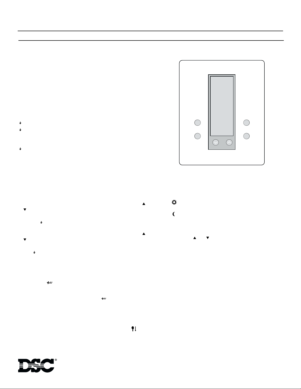
The HS-EMS300 Digital Communicating Thermostat is designed to pro-
vide accurate control and display of room temperature. The thermostat nor-
mally displays room temperature, mode of operation (i.e. Day or Night),
and whether Cooling or Heating is currently on. The six buttons on the
front of the unit allow complete control of the thermostat. You may specify
different Heating and Cooling setpoints, and change them easily by pushing
a button. Temperature can be displayed in either °C or °F. The thermostat
also allows you to select either continuous fan operation, or fan operation
only during operation of the heating/cooling device(s).
Modes of Operation
Select the desired mode of operation by toggling the MODE button:
—indicates Cooling system only. “COOL” is displayed for 5 seconds.
—indicates Heating system only. “HEAT” is displayed for 5 seconds.
—indicates both the Heating and Cooling (automatic). “AUTO” is
displayed for 5 seconds).
(flashing)—indicates Cool is ON.
(flashing)—indicates Heat is ON.
OFF—shuts off thermostat. Heating and Cooling systems will not operate.
Fan operation is still possible.
Caution: Avoid using the OFF mode during cold weather to prevent dam-
age from freezing.
❄
❄
❄
Temperature Control
Cooling:
Select the temperature you want the thermostat to maintain while in Cool
mode, press the mode button until Cool mode is selected, then press the
or buttons until the desired temperature is displayed. The cooling set-
point temperature is displayed for 5 seconds.
Heating:
Select the temperature you want the thermostat to maintain while in Heat
mode, press the mode button until Heat mode is selected, then press the
or buttons until the desired temperature is displayed. The heating set-
point temperature is displayed for 5 seconds.
Auto:
The thermostat will automatically switch from heating to cooling as deter-
mined by the selected setpoints in heating and cooling.
NOTE: The thermostat will not allow less than 1 C (2 F) difference
between the heating and cooling setpoints.
Fan Control
The Fan will come on automatically when the system is operating, but there
is no indication of this on the display. To select continuous Fan operation,
press the FAN button and the display will show . This is recommended
for electronic air cleaners and continuous ventilation requirements.
Outdoor (ODT) Button
When the outdoor temperature sensor option is connected to your thermo-
stat, you can display the current outdoor temperature by pressing the but-
ton. If this option is not connected, the thermostat will display _ _ with
no numbers.
Day/Night Button
The Day/Night button is used to select the Occupancy setting. When first
installed, the thermostat is set to Day occupancy setting and the display will
show the symbol and the Day temperature. By pressing the Day/Night
button you can change to the Night occupancy setting and the display will
show the symbol and the Night temperature. This button can be used to
toggle between Day and Night modes. Within each mode the temperature
can be modified. The thermostat will remember any new settings.
Celsius/Fahrenheit
Simultaneously press and to toggle between Celsius ( C) and Fahr-
enheit ( F) temperature display.
Optional Indoor/Outdoor Remote Sensors
The thermostat can accept indoor and outdoor remote temperature sensors
(EMS-ITS and EMS-OTS) for monitoring of temperatures where these
sensors are located.
Connecting indoor sensors disables the temperature sensor on the thermo-
stat thereby increasing the flexibility of where the thermostat can be
located. For temperature averaging over a large area a minimum of two
indoor sensors are required.
Indoor and outdoor sensors are available separately. For more details about
installing these sensors, please refer to the Installation Instructions included
with the sensors.
Temperature Accuracy
Full accuracy is only achieved after the thermostat has been installed and
powered for at least one hour.
Power Failures
No battery is required to maintain the temperature setpoints in the case of a
power loss, regardless of duration.
❄
❄
Mode
Fan
Outdoor
Day/Night
Table of contents
Other DSC Thermostat manuals


Popular Thermostat manuals by other brands

Aprilaire
Aprilaire 8710 owner's manual

heatwell
heatwell HT3 manual

Vive Comfort
Vive Comfort TP-S-855iCRH Operation manual

Chromalox
Chromalox PK407-3 Installation, operation and renewal parts identification

Friedrich
Friedrich WRT1 PTAC Installation and operation instructions

HaiLin Controls
HaiLin Controls Elegance SMT-700 user manual

Warmup
Warmup Terra RSW Series quick start guide

Jackson Systems
Jackson Systems WZ1 Installation and operation manual

ritetemp
ritetemp 8050C Operation manual

KTC
KTC SR 310/3 User instructions

Lux Products
Lux Products TX500b Series Installation and operating instructions

Filtrete
Filtrete 3M-22 Operation guide


