Introduction
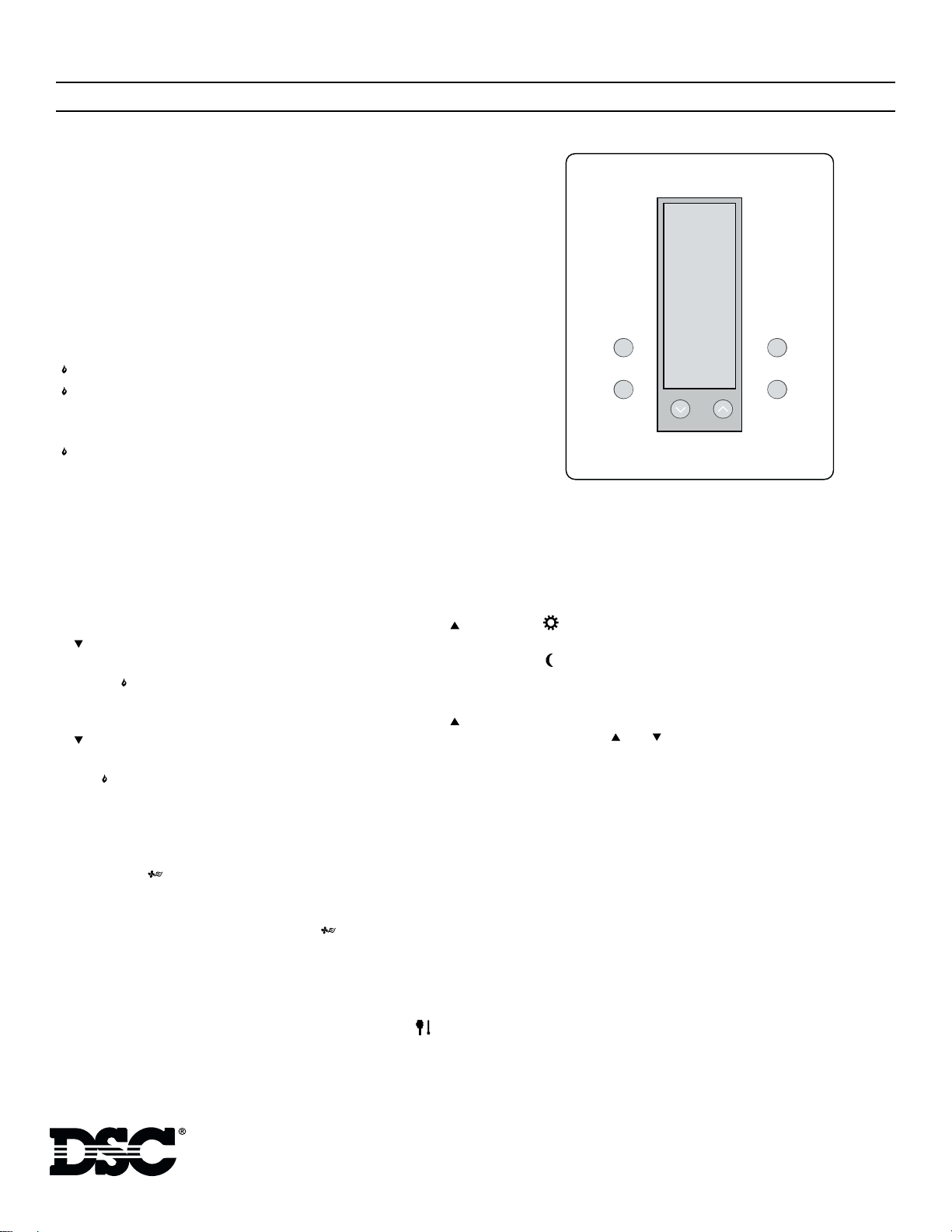
The HS-EMS400 is a 1 Heat / 1 Cool / Emergency Heat Electronic Digital
Communicating Non-programmable Thermostat designed for control of sin-
gle compressor Heat Pumps. It features an easy-to-read vertical LCD that
displays the current temperature and complete operation status. A direct
wire, easy-to-install backplate mounts on a standard vertical outlet box or
any drywall surface using the anchors and hardware provided.
This thermostat is designed to accept up to 6 indoor remote temperature sen-
sors (HS-EMS-ITS) or 5 indoor and 1 outdoor (HS-EMS-OTS) remote tem-
perature sensors. When indoor sensors are connected to the thermostat, the
temperature sensor (thermistor) on the thermostat is disabled. For tempera-
ture averaging at least two HS-EMS-ITS indoor remote sensors are required.
For additional information and wiring diagram for remote temperature sen-
sors, refer to the Installation Instructions included with the sensors.
The HS-EMS400 connects to an Escort/VPM5580TC, allowing the user to
change temperature settings through premise or remote touch tone tele-
phones. The Escort/VPM5580TC can announce the indoor temperature and
if an HS-EMS-OTS is connected, the outdoor temperature as well. Compati-
ble LCD keypads can also display the temperature and allow the user to
access the temperature controls (requires LCD5500 v2.1 or higher).
For information on thermostat access and control using the Escort/
VPM5580TC, please refer to the Installation Instructions included with the
Escort/VPM.
Location
For accurate temperature detection, the thermostat should be mounted on an
inside wall, 46 cm (18”) from any outside wall, in a frequently occupied area
with freely circulating air. It should be approximately 1.5 m (5’) above the
floor. Avoid direct sunlight, radiant heat from appliances, air conditioner
grills, stairwells, water pipes, warm air stacks, and sources of electrical inter-
ference such as arcing relay contacts.
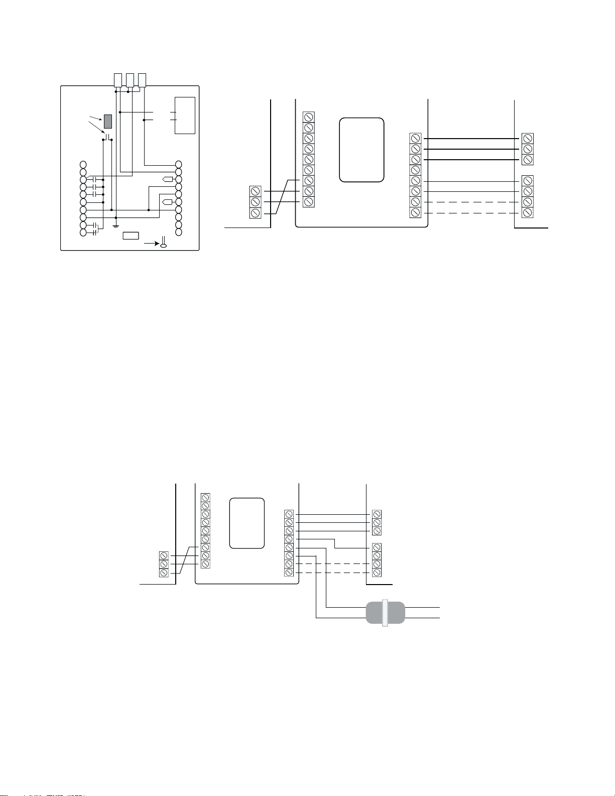
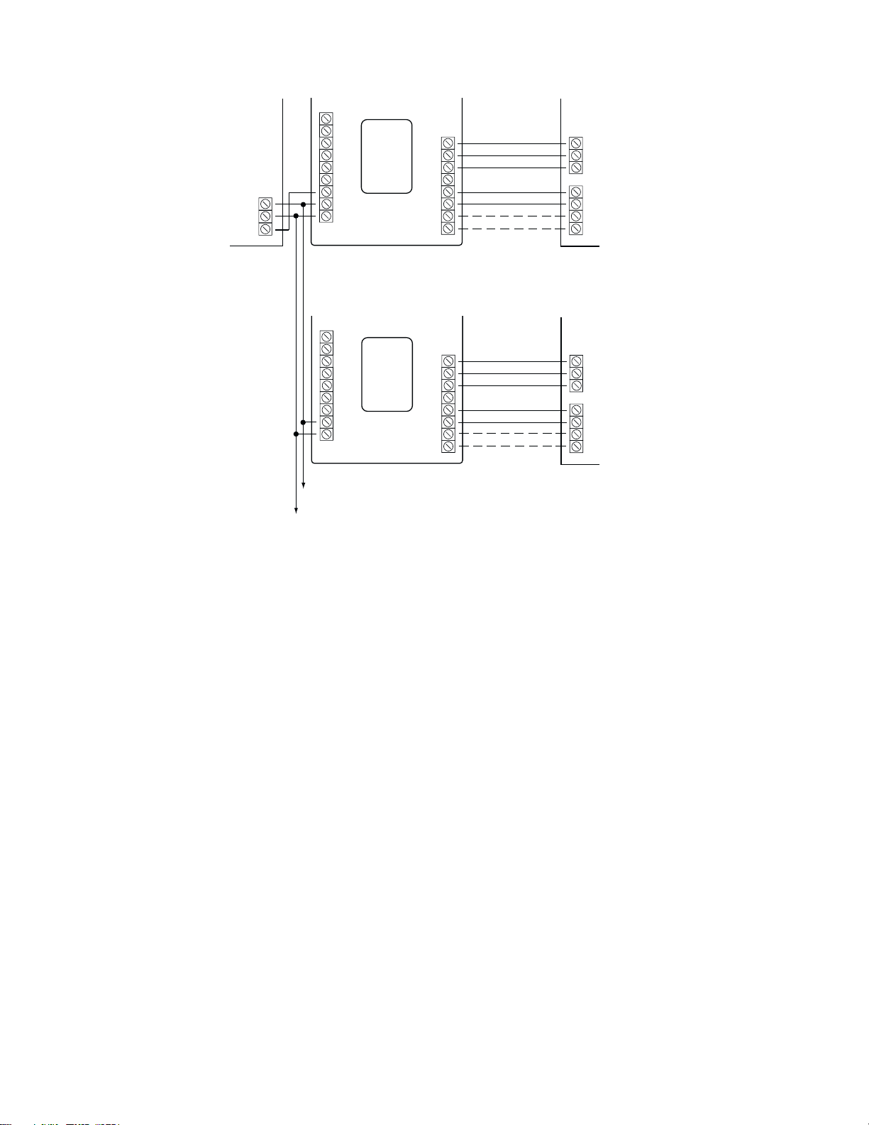
Pre-Wiring
The HS-EMS400 requires a 7 conductor wire when connected to a multi-
stage heating and cooling system plus an additional 3 conductor wire when
connected to a security system through an Escort or VPM module.
Installation
1. Remove the thermostat cover. Insert a flat blade screwdriver, approxi-
mately 3 mm (1/8”) into the slot located in the bottom center of the
case. Twist ¼ turn to pop the thermostat loose from the backplate.
2. Swing the thermostat out from the bottom (hinge at top) and lift the
thermostat up and off the backplate.
3. Place the backplate opening over the control wires protruding from the
wall. Use the backplate to mark the location of two mounting holes.
4. Drill two 5 mm (3/16”) mounting holes at the marked locations. Tap the
supplied nylon anchors flush to the wall and fasten the backplate using
the supplied screws. Do not over tighten.
5. Connect the control wires to the thermostat as shown in the appropriate
wiring diagram. Push any slack wire back into wall. Ensure that the
wires are flush with the backplate. Seal the access hole to prevent
drafts from affecting thermostat performance.
6. Install optional setback and indoor/outdoor remote sensors, if used.
7. Replace the thermostat by inserting the tabs into the hinge slots at the
top of the backplate. Gently swing the thermostat downward and snap
it into place.
8. Replace the thermostat cover.
Thermistor Position
When placing the front cover on the thermostat, ensure that the thermistor is
not touching the case. The thermistor should be placed horizontal to the wall
and visible between the ribs of the case.
Thermostat Cover Lock
Insert the plastic lock piece into the bottom of the mounted base. The ends of
the lock piece fit snugly under the lock pins extending from the bottom of the
mounted base. The tab in the middle of the lock piece extends down from the
base. To release the locking mechanism, press the lock piece up and into the
base while gently prying open.
DIP Switch Settings and Functions
The DIP switches are located on the interior of the thermostat and can be set
in either the ON or OFF position depending on the installation.The default
positions appear in bold.
1. Normal or Add-On Heat Pump In the normal position the thermostat
will allow the compressor and the emergency heat to be on at the same
time. In the add-on position, the compressor is turned off with a call for
emergency heat.
2. Not Used This switch must remain in the OFF position.
3. 2 Minute or 4 Minute ON Times This option allows you to select
either a 2 or 4 minute minimum off and on time.
4. Keypad Lock In the ON position, all buttons are locked out except the
OUTDOOR Temperature button to prevent tampering. If the keypad is
locked, the day setpoint may be overridden for 1 hour by ±3°C or ±6°F
by pressing the or buttons.
5. Economy or Comfort In the OFF/Economy position, the thermostat
will not allow the equipment to forced on with a change in setpoint. In
the ON/Comfort position, the equipment will turn on immediately with
a change in setpoint.
6. Not Used This switch must remain in the OFF position.
7. LED 1 + Indication In the OFF position, LED 1 will light when the ter-
minal is energized. In the ON position, LED 1 will light and a Filter
icon will be displayed on the LCD when the terminal is energized.
8. LED 2 + Indication In the OFF position, LED 1 will light when the ter-
minal is energized. In the ON position, LED 2 will light and a Fault
icon will be displayed on the LCD when the terminal is energized.
Specifications
Rated Voltage.............................................................................20-30 VAC, 24 VAC nominal
Rated AC........................................0.05-0.75 A continuous/output (surges to 3.00 A, max.)
Rated DC @ ‘R’ ............................0.00-0.75 A continuous/output (surges to 3.00 A, max.)
Control range: Heating............................... 5-30°C in (1° steps); or 38-88°F (in 1° steps)
Cooling........................... 16-40°C in (1° steps); or 60-108°F (in 1° steps)
Measurement range................................................................................ 0-48°C; or 28-124°F
ODT Measurement range .........................................................–48 to 47°C; or –50 to 119°F
Minimum deadband............................................(between heating and cooling) 1°C; or 2°F
NOTE: This thermostat contains electronic circuitry that replaces the con-
ventional mechanical anticipator.
DIP Switch DIP Switch OFF DIP Switch ON
1Normal Add on
2Not used (Off) Not used
34 Minute Min ON 2 Minute Min ON
4Keypad Unlock Keypad Lock
5Economy Comfort
6Not used (Off) Not used
7LED 1 + No Icon LED 1 + Filter Icon
8LED 2 + No Icon LED 2 + Fault Icon
HS-EMS400
Single-Compressor Heat Pump Thermostat
Installation Instructions