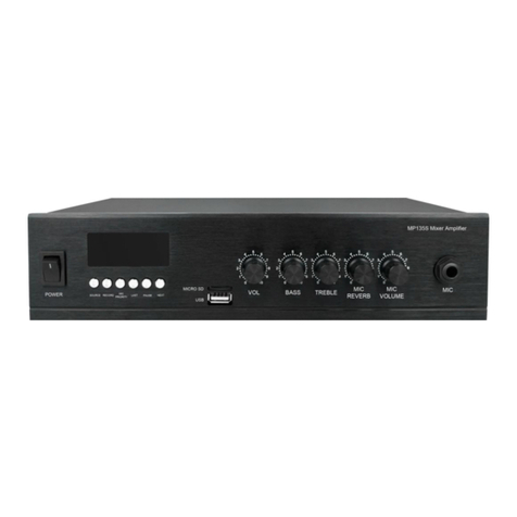
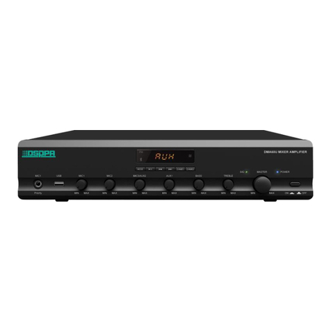
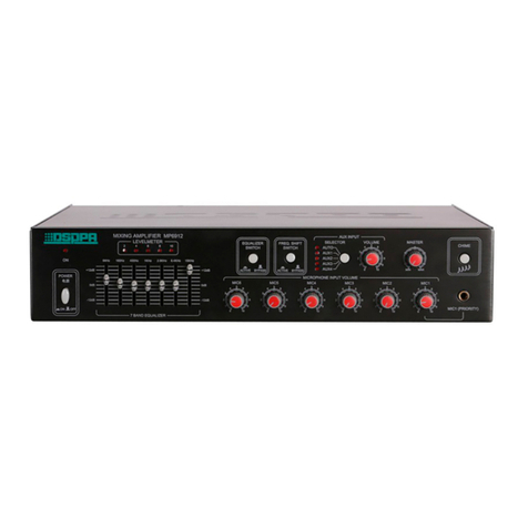
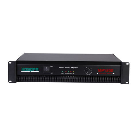
DSPPA DMA6250U User manual

DMA6250U
DMA6350U
DMA6500U
DMA6650U
User Manual
Guangzhou DSPPA Audio Co., Ltd
Mixer Amplifier
www.dsppatech.com

Leave this page blank for users to note

About this manual
This manual will be effective since the Mixer Amplifier is in operation. The manual contains
related system introduction, use precautions, system connection instructions, product usage
instructions of the Mixer Amplifier. Users are expected to read this manual carefully before
installing and using and strictly follow the instructions thereof.
The instructions with marks on the rear panel of the machine are all matters that must be paid attention to.
Please be sure to use or operate in accordance with these instructions when using it.
Please keep this manual properly in case you need it from time to time.
DMA—V1.3
Facture 2022-09-17

Matters Needing Attention
Please read the following carefully before any operation.
Warning
In order to avoid any potential personal injury as well as loss or damages to equipment or property, please
DO follow the basic instructions as given below. Such instructions include with limitation to the following:
Power supply/power wire
• Please hold the plug other than the power wire when
trying to remove the plug from sockets. Pulling the
power wire may result in damages.
• Please do NOT place the power wire anywhere near
the heat source. Please do NOT bend or buckle the
power wire or place it where it may be stepped on or
may trip passer-by.
• This equipment is connected to the power grid
through the plus, so when any fault or danger occurs,
the user should remove the plug from the socket to
disconnect the equipment from power grid, therefore,
it is important to place the power socket where it is
easily accessible.
• When the power switch of this equipment is "OFF",
the equipment is not disconnected from the power
source; therefore, for purposes of safety, the user
should remove the plug from power socket when the
equipment is not in use.
Installation Location
• Please disconnect the equipment from power source
before relocation.
• In order to avoid deformation of the panels and
damages to components, please do NOT place the
equipment where there is excessive dust, vibration or
extreme cold or hot conditions.
• Please keep this equipment off water drops or splash
or vase filled with water or any other articles of
similar nature.
Connection
• Please disconnect the power supply when the
equipment is connected to any other equipment.
Please turn the volume down to the minimum level
before switching on or powering off the equipment.
• Symbols of on any terminal in the equipment
indicate that such terminal is live and dangerous and
any connecting operation should be done by trained
personnel.
In case any abnormal condition is detected,
• If the power wire is worn or damaged, resulting in
sudden interrupt of sound or abnormal smell or smoke
during use, please cut off the power supply
immediately and have the equipment inspected by
professional personnel.
Matters needing attentions in operation
• Please do NOT put your finger in any gap or
opening of the equipment.
• Please keep any foreign matters (paper, plastic or
metal) from being inserted in any gap or opening of
the equipment. In such cases, please cut off the power
supply immediately.
• Please do NOT put any part of your body or any
heavy object on the equipment and please be careful
when operating any button or switch of the equipment
or when connecting the equipment.
Please do NOT disassemble the equipment
• Please do NOT remove the cover of the equipment;
otherwise you may get an electric shock.
• Please do NOT attempt to disassemble any
component of the equipment or make any
modifications in whatever manner. If any abnormal
phenomenon is observed, please stop using the
equipment immediately and have it inspected by
professional personnel.
Other Precautions
• Our company will be take responsibility for data loss
or damages resulting from improper user or
unauthorized modifications.
• All figures included in this Manual are for
description purposes and there may be slight
difference in your actual application. Please refer to
the actual product.

Contents
Preface .......................................................................................................................................................................... 1
Product Overview .........................................................................................................................................................1
Features .................................................................................................................................................................1
Front Panel ............................................................................................................................................................2
Rear Panel .............................................................................................................................................................4
Operating Instructions .......................................................................................................................................... 5
Remote Controller ................................................................................................................................................ 7
Technical Parameters ................................................................................................................................................... 8
Packing List .................................................................................................................................................................. 8

1
Preface
Thank you for choosing our products. All products are strictly tested before leaving the factory, honoring promise
of quality. The product is best applied to such places as schools, stadiums, squares, venues, parks, parking lots, the
railway station, the airport, the villas, the shopping mall, etc.
In order to better your installation, debugging and use of this product, please read this manual carefully before
installation.
Product Overview
Features
LCD lattice screen with backlight to display more information, more user-friendly;
Five-segment level indicator;
Built-in Bluetooth, FM, MP3 playback;
Two-channel RJ-45 remote paging microphone interfaces with zone control and strong cut function,
DC+24V power supply, 6 paging stations cascaded per channel, as far as 300m-600m transmission distance.
With independent volume adjustment knob of six zones ;
With strong cut and one-touch to switch functions when broadcast certain zones;
AC and DC24V power supply can be turned off;
4 microphone inputs, 1 emergency signal input, 4 line inputs and 1 line output;
70V/100V fixed voltage output and 4-16Ω fixed-resistance output;
With priority function, the order is MUTE>EMC IN=SIREN>MIC1>CHIME>Remote
paging>LINE1=MIC2/LINE2=MIC3/LINE3=MIC4/LINE4=MP3=BT=FM (no chime output when there is an
alarm sound);
With total volume control; Zone, Siren, Chime, EMC IN, MIC and AUX volume control; treble and bass tone
control;
SIRNE short-circuit trigger function, the device can be remotely controlled or controlled by other equipment,
with independent alarm sound output;
MUTE short-circuit triggered mute function, which can be controlled remotely or by other devices;
1-channel EMC alarm signal input to input alarm signals from other devices;
Can be controlled by an infrared remote control;
With power-off memory function, it will display the last content when powers on.
2
Front Panel
1.USB
Insert a USB flash drive here to provide programs to
the built-in MP3, whose memory is 32G;
2.SD Card
3. MIC1 Volume Adjustment Knob
Adjust the volume of the MIC1, clockwise to volume
up and counterclockwise to volume down;
4. LINE1 Volume Adjustment Knob
Adjust the volume of the LINE1, clockwise to volume
up and counterclockwise to volume down;
5. MIC2/LINE2 Volume Adjustment Knob
Adjust the volume of the MIC2/LINE2, clockwise to
volume up and counterclockwise to volume down;
6. MIC3/LINE3 Volume Adjustment Knob
Adjust the volume of the MIC3/LINE3, clockwise to
volume up and counterclockwise to volume down;
7. Bass Volume Adjustment Knob
With the center position as the reference, clockwise to
volume up and counterclockwise to volume down;
8. Treble Volume Adjustment Knob
With the center position as the reference, clockwise to
volume up and counterclockwise to volume down;
9. Main Volume Adjustment Knob
Adjust the volume of all signals (except the
emergency input signal on the rear panel), clockwise
to volume up and counterclockwise to volume down;
10. 6-Zone Volume Adjustment Knob & Indicator
Adjust the volume of 6 zones, clockwise to
volume up and counterclockwise to volume
down;
When the zone is open, the corresponding
indicator is blue;
11. Power Switch
Press down button“ON” to turn on the power, and
“OFF” to turn it off;
12. Protection Indicator (DC temperature,
overcurrent, or short circuit protection)
13. Level Indicator
Level display of audio output;
14 . Power Supply LED
15.FN Zone Switch
Short press to control zone 1-6 to be on or off, press it
to turn on the zones, then use the button “1”, “2”, “3”,
“4”, “5”, “6” on the panel to turn on or off the
corresponding zone. If you press the FN button for
more than 1s, all the zones will be opened, and if you
press the FN button for more than 1s again, the zones
will be restored to the state before they were all
opened.
16. Mode

3
The modes that can be switched are USB mode, AUX
line mode, Bluetooth play mode and FM radio mode;
17. LOOP Volume Adjustment Button
Adjustable volume of MIC4/LINE4, EMC, Chime,
and SIREN, volume 0-32 (for detailed operation,
please refer to No.8 of the "Operating Instructions"
item below);
18. Display screen
19. Chime button
20. Next song / (FM mode for next program)
In USB and Bluetooth modes, press this button to
the "next song";
In FM mode, press this button to the "next
program";
In FM, AUX, USB, SD and Bluetooth modes,
long press this button to turn down the volume of
MP3 sources (including FM, SD, USB and
Bluetooth)
21.Infrared Remote Control Receiving
22. Previous Song / (FM mode for previous
program)
In USB and Bluetooth modes, press this button to
the "Previous song";
In FM mode, press this button to the "Previous
program";
In FM, AUX, USB, SD and Bluetooth modes,
long press this button to turn up the volume of
MP3 sources (including FM, SD, USB and
Bluetooth)
23. Play/Pause
In USB and Bluetooth modes, press this button to
Pause;
In FM mode, press this button to the search;

4
Rear Panel
Take the rear panel of DMA6250U as an example
1. Power Input Connector AC230V
Access the power plug to this connector. When
connecting, please insert the plug of this device first,
and then connect to the grid.
2. 6-zone Output
3. LINE Output
4. LINE1 Input
5. MIC1 Balanced Input
6. MIC2, LINE2 Input
7. MIC3, LINE3 Input
8. MIC4, LINE4 Input
9. EMC Trigger Input
10. SIREN Short-circuit Trigger
11. Silent Short-circuit Trigger
12. FM Antenna
13. Fan Port
14. LINE4, MIC4 Phantom Voltage Switch
Toggling the switch to left and right (Note: When
toggle this switch, you need to turn down the volume
of the device or turn off the power of the device first)
15. LINE3/ MIC3 Phantom Voltage Switch
Toggling the switch to left and right (Note: When
toggle this switch, you need to turn down the volume
of the device or turn off the power of the device first)
16. LINE2/ MIC2 Phantom Voltage Switch
Toggling the switch to left and right (Note: When
toggle this switch, you need to turn down the volume
of the device or turn off the power of the device first)
17. MIC1 Phantom Voltage Switch
Toggling the switch to left and right (Note: When
toggle this switch, you need to turn down the volume
of the device or turn off the power of the device first)
18. DMA20 Remote Paging MIC Input
19. Fixed resistance and voltage output
Fixed resistance/voltage Speakers
20. DC+24V Power Input (emergency power input)

5
Operating Instructions
1. Initial Start-up
When starting up the stereo amplifier for the first time, do as follows:
1) Turn down the total volume.
2) Turn down the zone volume.
3) Connect the stereo amplifier to the power supply; Turn on the amplifier till the power indicator is on.
4) Turn the total volume to the optimal level.
5) Adjust the zone volume until it reach the desired volume output. If you need to change the wiring or
installation, make sure to disconnect the power cord from the device first.
2. Mic Broadcast
Conduct MIC broadcast in any mode, the system detects the microphone's voice and mutes other audio
sources; When the microphone has no signal, it automatically backs to the original playback state.
3. Bluetooth Mode
Press the MODE button until the digital screen displays Bluetooth and Bluetooth name, as shown below, then
please open the cellphone or other Bluetooth devices, find the device with Bluetooth name of "6 ZONES AMP
BT” for pairing. After that, music can be streamed from phone (when the device and cellphone Bluetooth pairing
successful, the digital display will stop flashing), wireless transmission distance is about 10m.
4. USB Mode
When insert a USB, it will automatically come to USB mode (plug and play). As shown below, the interface
displays the current playing song name, playing duration, playing mode, playing status and volume level. In USB
mode, short press LOOP button to switch the playback mode to random play, single loop, directory loop.
Random Play Directory Loop Single Loop
5. Line Mode
Press the MODE button until the digital screen displays AUX to enter Line Mode, as shown below.

6
6. FM Mode
For button description, please refer to the instructions in "Front Panel" above, sections 20, 22 and 23. Press
MODE button until the digital screen displays FM to enter FM mode, as shown below; Then it will start to play
radio programs.
1) Searching radio stations: Before playing, search radio stations first, the FM band radio frequency range is
87.00MHz - 108.00MHz.
Methods of searching for Radio Stations: Short press button
on the panel or remote control to search
automatically from low to high frequency bands. The searched stations will be stored in number starting with
1, so that the stations can be recalled directly later.
2) Calling radio stations: search and store good radio channels with automatic search method, and you can call
and play them directly. Press button” / ”on the panel to choose radio stations you want to play, or
press number “0-9” to play.
7. 6-zone Control Switch
Short Press the button FN to enter the zone setting interface, and the "1", "2", "3", "4", "5" and "6" buttons on
the panel can be used to turn on or off the corresponding zones as shown in the figure below. Press and hold the
FN button for more than 1s to open all zones. At the same time, the indicator lights at the 6 zone volume
adjustment knobs on the device panel display bright blue, and then press again to back to the state it was in before.
8. Adjust Volume of Audio Source
Volume of 6 zones/MIC1/MIC2/MIC3/LINE1/LINE2/LINE3 can be adjusted directly through the
corresponding volume knob on the panel.
Volume of MIC4/LINE4, EMC, Chime, SIREN: long press the LOOP volume adjustment button to enter the
volume setting interface, then short press the LOOP button again and select MIC4/LINE4, EMC, Chime,
SIREN alarm setting interfaces, press button "V+/ V-" to adjust the volume of the corresponding audio
source through the panel(0-32).

7
MP3 audio source(FM/AUX/USB/SD/Bluetooth) volume: in the FM/AUX/USB/SD/Bluetooth mode, long
press “ ” or “ ” previous or next song button to enter the MP3 volume settings interface, continue to
long press the “ ” or “ ” previous or next song button to adjust the MP3 audio source volume level
(0-32).
9. Phantom Power
Switch on the phantom power switch to provide phantom power (+ 48V) to all green terminal microphone inputs.
It is not recommended to switch on for normal use but only used for MIC1, MIC2/LINE2, MIC3/LINE2,
MIC4/LINE2.
Remote Controller
As shown in the following figure, remote controller keys are introduced in details.
1 Standby Switch
2 Mode Selection: Click it to display modes in turn: FM, USB,
AUX and BT.
3 MUTE button.
4 EQ Mode, with 4 optional sound effects.
5 Play Control Area. Play/Pause, Previous/Next, and Volume
Control.
6Loop Mode. Click it to display modes in turn: Single Loop,
Random Play and Directory Loop.
7Number Area. In FM mode, press the number directly to enter
the FM frequency that has been stored.
8 Alternative Button

8
Technical Parameters
Packing List
No.
Checklist
QTY
1
Mini Mixer Amplifier
1
2
Remote Controller
1
3
Certificate of Conformity
1
4
Warranty Card
1
5
Manual
1
6
Charters Washer
4
7
Handle
2
8
16P Green Plug/3.81mm pitch
1
9
12P Green Plug/5.08mm pitch
1
10
Power Cable
1
11
Countersunk Head Cross Screw Black /3×8
6
12
Half Countersunk Head Cross Screw Black /5×19
4
Model
DMA6250U
DMA6350U
DMA6500U
DMA6650U
Power
AC230V 50/ 60Hz
Input
Sensitivity
MIC1
10mV ±1mv (Balanced XLR Input)
MIC2/MIC3/MIC4
10mV ±1mv (Unbalanced Phoenix Jacks)
AUX1
350mV±50mv (Unbalanced RCA Input)
AUX2
350mV ±50mv (Unbalanced Phoenix Jacks)
EMC
350mV ±50mv (Unbalanced Phoenix Jacks)
MIC Frequency Response
120Hz~12kHz (±3dB)
AUX Frequency Response
80Hz~15kHz (±3dB)
THD
<1%
Treble Adjustment Range
10dB(±2)
BASS Adjustment Range
10dB(±2)
Phantom Power
+48V
Rated Output Power
250W
350W
500W
650W
Output Voltage of Port
4-16Ω,70V,100V(fixed voltage output)
Current
2A
3A
4A
Protection
F3.15AL
F6.3AL
F8AL
Machine Dimension(D×W×H)
430×390×88mm
Package Dimension:
545×500×165mm
Net Weight
8.6KG
9KG
10.1KG
11KG
Gross Weight
9.8KG
10.2KG
11.3KG
12.2KG

© DSPPA Audio 丨The specification will be subject to change without notices.
Guangzhou DSPPA Audio Co., Ltd.
Address: No.1 Xiahe Road, Jianggao Town, Baiyun District, Guangzhou, China
Post Code: 510450
Tel: +86-20-37166520
Website: www.dsppatech.com
This manual suits for next models
3
Table of contents
Other DSPPA Amplifier manuals