DTL Broadcast 5AA2625 User manual

CCIR noise (quasi peak)
transformer/electronic
<90dBq unweighted
84dBq weighted
<83dBq unweighted
<80dBq weighted
Inter-channel cross-talk <109dB @ 1kHz <109dB @ 1kHz
Inter-module cross-talk <109dB @1kHz <109dB @1kHz
Other
Power supply required 230VAC 50Hz
Power Consumption 10VA max
Temperature range 0°C to 40°C
Measurements relate to 5AA2625 ADA with the 5AA2626 connector unit in a 5AV2645 frame
driving high impedance loads (1k
Ω
and above) unless otherwise indicated
Physical
Weight Height Width Depth
5AA2625 650g 88mm(2U) 44mm(1U) 300mm
5AA2625-1 675g 88mm(2U) 44mm(1U) 300mm
5AA2625-2 700g 88mm(2U) 44mm(1U) 300mm
5AA2625-4 750g 88mm(2U) 44mm(1U) 300mm
5AA2625-6 800g 88mm(2U) 44mm(1U) 300mm
DTL 2600 range
User Guide
5AA2626 150g 88mm(2U) 44mm(1U) 130mm
5AA2626-5 200g 88mm(2U) 44mm(1U) 130mm
3990 45g 54mm 16mm 115mm
5AA2626-1 150g 88mm(2U) 44mm(1U) 130mm
5AA2626-2 150g 88mm(2U) 44mm(1U) 130mm
5AA-K N/A N/A N/A N/A
5AA-OP600 N/A N/A N/A N/A
5AA2627 150g 88mm(2U) 44mm(1U) 300mm
5AA2625 single/dual channel audio
distribution amplifier
www.dtl-broadcast.com
DTL Broadcast Ltd, Johnson’s Estate, Silverdale Road, Hayes, Middlesex, UB3 3BA, UK
Phone: +44 (0) 20 8813 5200 Fax: +44 (0) 20 8813 5022
Internet: www.dtl-broadcast.com support@dtl-broadcast.com
\\Dtl-server\company\PRODUCTS\2600\User Guides\UG5AA2625 Iss1.0.doc
- 8 -

Ordering information
Features
5AA2625 ADA dual channel 5 balanced output (single channel 10 output) with
electronic high Z inputs & low Z outputs
5AA2625-1 ADA as 5AA2625 but with transformer inputs
5AA2625-2 ADA as 5AA2625-1 with 1 output transformer per channel
5AA2625-4 ADA as 5AA2625-1 with 2 output transformers per channel
5AA2625-6 ADA as 5AA2625-1 with 3 output transformers per channel
5AA2626 Audio rear connector with D type socket (suitable for multi-core cable
with common screen)
5AA2626-5 Audio rear connector with two D type sockets (suitable for multi-core
cable with common screen)
3990 D type to removable screw terminal adapter
5AA2626-1 Audio rear connector with two ½ DIN solder tag connectors on a
removable sub-assembly (suitable for individually screened twisted
pair cable)
5AA2626-2 Rear connector with removable screw terminals
5AA-K Gain trimmer replaced by panel mounted knob (per channel)
5AA-OP600 600Ωoutput impedance option
A broadcast quality dual / single channel audio distribution amplifier with:
•Front panel gain controls and output monitoring test points for each
channel (optional gain potentiometers with knobs)
•5 balanced outputs per channel of which up to three per channel can be
transformer-coupled. Easily configured to single channel 10 output
distribution amplifier by link selection
•Electronic or optionally transformer balanced inputs (user selectable high
or 600Ωimpedance)
•Low impedance outputs (optional 600Ωimpedance)
•Input and output transformers achieve wide frequency response and low
distortion even at low frequencies using novel circuitry
•Two stereo to mono outputs available by link selection
•A link can be moved to bypass the roll-off filter for time-code distribution
•Requires the 5AA2626, 5AA2626-1 or 5AA2626-2 rear connector unit
•The 5AA2626 incorporates all input and output connections on a 25 way
D type socket, ideal for multicore cable with a common screen (the 3990
D type to removable screw terminal adapter is available as an option)
Specification
Input Electronic Transformer
Type Balanced Balanced
Impedance 50kΩ(or 600Ω) 16kΩ(or 600Ω)
Balance @ 1kHz >70dB >70dB
Max level +25dBu +25dBu
Output
Number 5 balanced per channel (up to 3
per channel with transformer)
5 balanced per channel (up
to 3 per channel with
transformer)
Impedance 48Ω(optional 600Ω) 31Ω(optional 600Ω)
Balance @ 1kHz 60dB (typically) >80dB
Isolation @ 1kHz >75dB >84dB
Max level +25dBu (20Hz to 20kHz) +18dBu @20Hz +20dBu
+20dBu (40Hz to 20kHz)
Performance
Gain range -20dB to +20dB -20dB to +20dB
Response
CCIR filter
±0.1dB (20Hz-15kHz) -
0.25dB @ 20kHz -
3dB @ 40kHz smooth roll off
thereafter
±0.1dB (20Hz-15kHz)
-0.25dB @ 20kHz
-3dB @ 40kHz
smooth roll off thereafter
No filter ±0.1dB (20Hz-30kHz) -
1dB @ 100kHz
±0.1dB (20Hz-30kHz)
-1dB @ 100kHz
THD+N (20Hz to
20kHz) electronic input
<0.005% @ 0dBu
<0.006% @ +8dBu
<0.015% @ +20dBu
<0.009% @ 0dBu
<0.008% @ +8dBu
<0.015% @ +18dBu
THD+N (20Hz to
20kHz) transformer
input
<0.055% @ 0dBu
<0.056% @ +8dBu
<0.045% @ +18dBu
<0.045% @ 0dBu
<0.045% @ +8dBu
<0.095% @ +18dBu
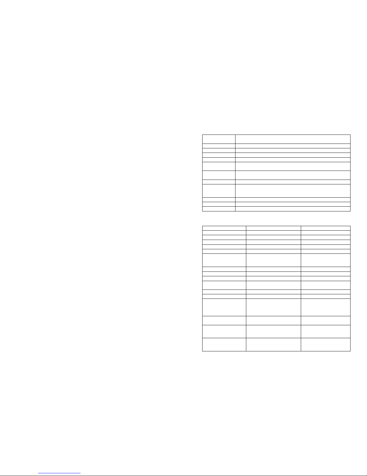
•The 5AA2626-1 has two ½ DIN connectors on a removable sub-
assembly, ideal for individually screened twisted pairs
•The 5AA2626-2 has removable Weco screw terminals
•All 2600 modules are independently mains powered maximising
reliability & isolation between modules.
Installation
Systems are generally delivered with modules (including sub-modules) and
associated rear connector units already installed and configured within frames to
your requirements.
Before installing or re-arranging modules and rear connector units in 2600
series frames the 2600 range and frames user guide should be consulted. Section
1.3 ‘Safety and pre-installation checks’ includes instructions that must be
followed. Section 2 describes how to install or re-arrange modules and rear
connector units in 2600 series frames.
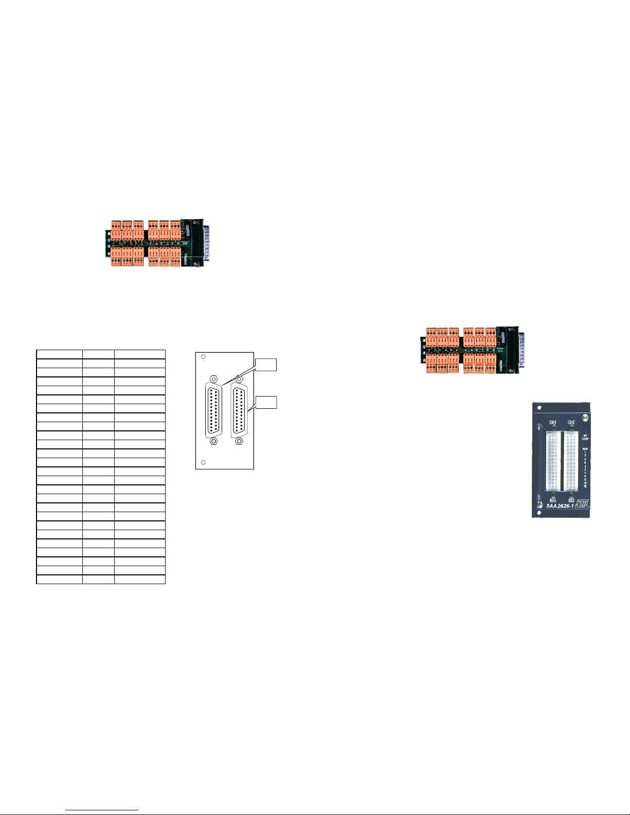
5AA2626 rear connector units
Input & output connections should either be made to a 25 way D type plug (not
provided) per the table 1 pin out details below, or when the 3990 D type to
screw terminal adapter is used, per the details shown below.
- 2 - - 7 -

5AA2626-2 rear connector units Table 1
The column for channel one is marked ‘CH1’ and for
channel two marked ‘CH2’. (When used a single channel
ADA only use the channel one input.)
- 3 -
D type pin Phase Use
1 + hot OUT5 (A) CH1
14 - cold OUT5 (A) CH1
2 + hot OUT4 (A) CH1
15 - cold OUT4 (A) CH1
3 + hot OUT3 (A) CH1
16 - cold OUT3 (A) CH1
4 + hot OUT2 (A) CH1
17 - cold OUT2 (A) CH1
5 + hot OUT1 (A) CH1
18 - cold OUT1 (A) CH1
6 + hot OUT5 (B) CH2
19 - cold OUT5 (B) CH2
7 + hot OUT4 (B) CH2
20 - cold OUT4 (B) CH2
8 + hot OUT3 (B) CH2
21 - cold OUT3 (B) CH2
9 + hot OUT2 (B) CH2
22 - cold OUT2 (B) CH2
10 + hot OUT1 (B) CH2
23 - cold OUT1 (B) CH2
11 + hot IN (B) CH2
24 - cold IN (B) CH2
12 + hot IN (A) CH1
25 - cold IN (A) CH1
13 N/A Chassis
Inputs are connected to the row marked ‘IN’. Outputs are
connected to rows marked outputs ‘OUT1 to 5’.
Input & output connections are made to twelve removable
Weco connectors
Pin columns for input & outputs are marked on the rear
unit '+' (In phase), ‘-' (Out of phase) and 'Earth sign'
(Screen). The same convention must be used to ensure
zero phase difference through the amplifier.
Front module
The 5AA2625 fits into the frame from the front and is secured by a
thumbscrew. This may be done with the frame powered.
A red LED, when lit, shows that the unit is receiving mains and the internal
power supply is functioning.
The front panel gain controls are factory set for unity. Turning the control
clockwise increases gain. When used as a single channel unit, use the channel 1
gain control only. Output level can be monitored from the front panel test
points.
Input termination. Units are delivered with high impedance inputs on both
channels. 600Ωtermination can be selected by fitting a jumper to the sets of
pins at the front of the module marked ‘CH1 600R’ and ‘CH2 600R’.
Single/dual channel. The unit is delivered set for dual channel operation. It can
be changed to single channel mode by moving the pair of jumpers (in the
middle of the unit) from the position marked 'DUAL' to that marked ‘SINGLE’. There are 5 outputs per channel. Any outputs without transformers fitted are
available as electronic ones. For the 5AA2625-2 with one output transformer
per channel, the output transformer is on output 1, for the 5AA2625-4 with two
output transformers per channel, the output transformers are on outputs 1&2, for
the 5AA2625-6 with three output transformers per channel, the output
transformers are on outputs 1, 2 & 3. When the stereo to mono function is
selected, the mono output is on output 5 for the channel selected.
The 5AA2626 rear connector can be used with the 3990 D type to removable
screw terminal adapter. Individual screened twisted pairs can be connected for
each input/output with hot (in phase) on the left, screen in the centre and cold
(out of phase) on the right. Inputs & outputs are shown on the unit.
Filtering. The unit is delivered with the CCIR roll off filter in circuit for both
channels. To bypass the filter for distribution of time code, move the jumper for
the relevant channel ('CH1' or 'CH2') from the position marked 'CCIR' to that
marked ‘OUT’. These jumpers are in the middle of the unit near the front.
Stereo to mono. The unit is delivered as a 5 balanced output dual channel
distribution amplifier. Moving the links marked ‘CH1 S>M’ and ‘CH2 S>M’
from ‘OUT’ to ‘IN’ provides a combined mono output on output 5 for channel 1
& 2 respectively.
- 6 -

There are 5 outputs per channel. Any outputs without transformers fitted are
available as electronic ones. For the 5AA2625-2 with one output transformer
per channel, the output transformer is on output 1, for the 5AA2625-4 with two
output transformers per channel, the output transformers are on outputs 1&2, for
the 5AA2625-6 with three output transformers per channel, the output
transformers are on outputs 1,2&3. When the stereo to mono function is
selected, the mono output is on output 5 for the channel selected.
5AA2626-5 rear connector units
Input & output connections should either be made to 25 way D type plugs (not
provided) per the table 2 pin out details below, or when the 3990 D type to
screw terminal adapter is used, per the details shown below.
Table 2
D type pin Phase Use
1
14
2
15
3
16
4
17
5
18
6 + hot OUT5
19 - cold OUT5
7 + hot OUT4
20 - cold OUT4
8 + hot OUT3
21 - cold OUT3
9 + hot OUT2
22 - cold OUT2
10 + hot OUT1
23 - cold OUT1
11
24
12 + hot IN
25 - cold IN
13 N/A Chassis
3990 D type to removable screw terminal adapter
The 5AA2626-5 rear connector can be used with the 3990 D type to removable
screw terminal adapter. Individual screened twisted pairs can be connected for
each input/output with hot (in phase) on the left, screen in the centre and cold
(out of phase) on the right. Inputs & outputs are shown on the unit.
5AA2626-5
CH2
CH1
- 5 -
3990 D type to removable screw terminal adapter
5AA2626-1 rear connector units
Input & output connections are made to two half-size DIN
41612 connectors, one for each channel. These are
mounted on a sub-assembly to allow cabling to be carried
out on the bench.
Pin columns for input & outputs are marked on the rear
unit 'I' (In phase), 'O' (Out of phase) and 'S' (screen). The
same convention must be used to ensure zero phase
difference through the amplifier.
Top two rows of pins on each connector are in parallel to
allow input connections to be looped out if required.
Outputs are connected to rows marked outputs 1 to 5.
Screen pins are connected to chassis.
A tie bar on the connector sub-assembly allows cables to be secured properly.
The sub-assembly must be secured to the rear unit by its two captive screws
after cabling.
When used as a 10 output single channel distribution amplifier, use channel 1
input.
For unbalanced inputs connect one leg (I or O) to screen. For unbalanced
outputs use one leg (I or O) relative to screen. Never connect an output leg to
screen directly. Unused outputs must be left floating.
- 4 -
Table of contents
Other DTL Broadcast Amplifier manuals