dtm SLIM3 ECO LED User manual

PL
DE
EN
FOTOKOMÓRKA NATYNKOWA
Instrukcja obsługi i montażu
A -LUFPUTZ ICHTSCHRANKE
Betriebs- und Montageanleitung
PHOTOCELL
Operation and assembly manual
v.1.1


1. Informacje ogólne
Fotokomórka składa się z nadajnika i odbiornika. Dostępna w wersji SLIM3 ECO oraz w wersji
SLIM3 ECO LED wyposażonej w moduł lampy. Dodatkowa sygnalizacja optyczna pełni funkcję
ostrzegawczą oraz pozwala w warunkach słabej widoczności łatwiej zlokalizować wjazd.
Odbiornik posiada wyprowadzone styki sterujące typu NC i NO, których obwód
zabezpieczony został dodatkowym przekaźnikiem. Fotokomórka przeznaczona jest do pracy
wsystemachbramowych,jakoelementbezpieczeństwa pracujący nazewnątrz.
2. Dane techniczne
Parametry podstawowe
•gabarytyzewnętrzne obudowy
(szer.xgłęb. xwys.): 37x36x120mm
•sposóbmontażu: obudowa natynkowa,bryzgoszczelna,IP-54
•materiałobudowy: poliwęglan
•temperaturapracy (min./max.): -20°C / +55°C
•waga: 80g
•gwarantowanyzasięg działania: 1-15m
•zasilanienadajnika iodbiornika: 12...24VAC/DC±10%
•pobórprądu odbiornika: max.25mA
•pobórprądu nadajnika: max.25mA
Parametry lampy sygnalizacyjnej (wersja LED)
•zasilanielampy sygnalizacyjnej: 12...24VAC/DC ±10%
•pobórprądu: max. 150mA
•trybypracy: ciągły lubimpulsowy,wbudowanyprzerywacz
•technologia: LED
•odpornośćna wstrząsyi wibracje: wysoka
Elementy wykonawcze
•wyjściastykowe
(typ/ maksymalneobciążenie): NOlub NC / 1A(24VAC/DC)
Funkcjonalność
•regulowanykąt patrzenia: 180° w poziomie w nadajniku i odbiorniku, umożliwia
zamontowanie fotokomórki na płaszczyźnie
równoległejdo bramy
•interfejsużytkownika: sprzętowy interfejs na dwóch diodach LED
sygnalizujących podłączenie zasilania oraz
ułatwiające synchronizacjępromienia nadajnika z
odbiornikiem
•dodatkowezabezpieczenie: u k ła d w y j śc i o w y o z w i ęk s z o n y m s t o p n i u
bezpieczeństwa (w przypadku uszkodzenia, wyjście
fotokomórkiprzechodzizawsze wstan naruszenia)
PL

3. Montaż fotokomórki
Nadajnik i odbiornik należy zamontowaćna
wysokości 40 - 60 cm od ziemi. Odległość
pomiędzy nadajnikiem i odbiornikiem nie
powinna byćmniejsza niż1 m. Fotokomórka
posiada regulacjękąta patrzenia zarówno w
odbiorniku jak i w nadajniku. Nie jest wymagany
montażwspółosiowy, należy jedynie uwzględnić
maksymalne kąty obrotu płytek elektronicznych
w obudowach nadajnika i odbiornika.Ze względu
na elementy fotoczułe odbiornika, zaleca się
m o n t o w a n i e o d b i o r n i k a p o m n i e j
nasłonecznionej stronie. Zarówno nadajnik jak i
odbiornik fotokomórki należy montować
pionowo, listwy przyłączeniowe oraz otwory
odprowadzające wilgoćw pokrywie, powinny
znajdowaćsięw dolnej części obudowy.
Odpowiednie ustawienie nadajnika i odbiornika
ułatwia dioda RX, która świeci gdy promień
nadajnika dociera do odbiornika. Każdąz
obudów mocuje siędo powierzchni montażowej
przy pomocy 2 (montowane po przekątnej) lub 4
wkrętówznajdujących sięwzestawie.
Nie montowaćzwierciadełani ekranów
odbijających w obszarze działania fotokomórki,
odbiornik należy w miaręmożliwości montować
po stronie mniej nasłonecznionej, nie należy
montowaćodbiornika fotokomórki w miejscu
narażonym na oświetlenie silnym źródłem
obcego światła, zwłaszcza pochodzącego z lamp
jarzeniowych, gdyżmoże to zakłócaćpracę
bariery. Należy uważaćaby nie zabrudzić
elementów optycznych nadajnika /odbiornika
podczasmontażu.
UŻYJ TEGO RYSUNKU JAKO SZABLONU
Legenda:
1. podstawa obudowy (SLIM3 ECO czarna,
SLIM3 ECO LED pomarańczowa)
3. uchwyt płytki elektroniki z soczewką
2. moduł LED (wersja SLIM3 ECO LED)
Rys. 1 Rozstaw otworów mocujących w skali 1:1,
wraz z rysunkiem złożeniowym.
4. płytka elektroniki fotokomórki
6. mocowanie klosza
5. bryzgoszczelny klosz zewnętrzny
18 mm
92 mm
1
2
3
4
5
6

Centrala sterująca
WE sygnałowe
fotokomórka (NC)
WY zasilania akcesoriów
12-24V AC/DC
WY zasilania lampy sygnalizac.
12-24V AC/DC
ZASILANIE, polaryzacja nieistotna
SYGNAŁ STERUJĄCY
ZASILANIE LAMP SYG.
sygnalizacja:
RX
PWR
*zwora
przerywacza
modułu LED
nadajnik - TXodbiornik - RX
odbiornik - RX
NC CNO 12-24V
AC/DC
opisy zacisków
nadajnik - TX
LAMP
12-24V
AC/DC
LAMP
12-24V
AC/DC
12-24V
AC/DC
Rys. 2 Schemat elektryczny podłączenia fotokomórki.
Jeżeli urządzenie, do którego podłączona jest lampa nie ma
wbudowanego przerywacza, można uruchomićwbudowany
w lampach impulsator, poprzez założenie zworki na module LED.
*
Tryb pracy lampy
(wersja LED):
zawora założona
- tryb impulsowy
zwora zdjęta
- tryb ciągły
*
4. Podłączenie elektryczne fotokomórki
Fotokomórka współpracuje z centralami sterującymi automatykąbramową. Zaleca się, by
instalacjęelektrycznąi podłączenie fotokomórki wykonała osoba z odpowiednimi
kwalifikacjami. Podłączenie należy przeprowadzićzgodnie ze schematem przedstawionym
narys. 2oraz wgponiższego opisu:
Podłączyćzasilanie12-24VAC/DCdonadajnika i do odbiornikafotokomórki.
DiodyPWR wnadajniku iw odbiornikuoraz diodaRX wodbiorniku, powinnyświecić.
Jeśli użyto zasilania AC, należy zasilaćnadajnik i odbiornik przy użyciu tej samej fazy
(zjednego zasilacza).
Podłączyćwyjście sygnałowe odbiornika fotokomórki (zwykle NC i C) do
odpowiedniego wejścia w centrali sterującej. Należy zwrócićszczególnąuwagęna sposób
sterowania (NC lub NO) wymagany w centrali. Standardowym rozwiązaniem w automatyce
bramowejjest pracaczujnikówoptycznych wkonfiguracjiNC.
PL

5. Podłączenie elektryczne lamp sygnalizacyjnych (wersjaSLIM3 ECO LED)
Fotokomórki SLIM3 ECO LED posiadająmoduły sygnalizacyjne. Lampy przeznaczone sądo
współpracy z wyjściem sygnalizacyjnym centrali sterującej automatykąbramową. Moduły
LED należy podłączyćdo wyjścia sygnalizacyjnego o napięciu wyjściowym 12..24V AC/DC.
Moduły posiadająwbudowany przerywacz. Jeżeli urządzenie, do którego podłączona jest
lampa nie ma wbudowanego przerywacza, można uruchomićwbudowany w lampach
impulsator, poprzez założenie zworki na module LED. Przykład podłączenia lamp
przedstawionyzostałna rysunku2.
6. Próby odbiorcze
Po podłączeniufotokomórki, należydokonaćtestu, czyli sprawdzićreakcjęodbiornika(RX) na
przecięcie bariery świetlnej. Systemy automatyki bram musząbyćtestowane z
uwzględnieniemnormy EN12453.
Testparyfotokomórek:
-podłączyćzasilanie tylkodoodbiornika isprawdzićczy diodaRX jestzgaszona.
-podłączyćzasilanie takżedo nadajnikai sprawdzićczydioda RXzostała zapalona.
-przesunąć walec o średnicy5 cm i długości 30 cm przecinającprostopadle ośoptycznąmiędzy
nadajnikiem a odbiornikiem, najpierw w pobliżu nadajnika TX, potem w pobliżu odbiornika
RX, a następnie w połowie odcinka między nimi. Za każdym razem fotokomórka powinna
przełączaćsięzestanu czuwaniaw stanalarmu, cojest widocznepoprzez zgaśnięciediody RX.
-jeśli podłączonosprawdzićdziałanie lampsygnalizacyjnych.

1.Allgemeine Informationen
Die Lichtschranke besteht aus einem Sender und einem Empfänger. Erhältlich in der Version
SLIM3 ECO und in der Version SLIM3 ECO LED, ausgestattet mit einem Lampenmodul. Eine
zusätzliche optische Signalisierung dient als Warnfunktion und erleichtert das Auffinden des
Eingangs bei schlechten Sichtverhältnissen. Der Empfänger verfügt überSteuerkontakte vom
Typ NC und NO, deren Stromkreis durch ein zusätzliches Relais geschützt ist. Die
Lichtschranke ist für den Einsatz in Toranlagen als Sicherheitselement im Außenbereich
vorgesehen.
2.Technische Daten
Basisparameter
•Außenabmessungen
desGehäuses (BxTx H): 37x36x120mm
•Montage: Aufputz-Gehäuse, spritzwassergeschützt,IP-54
•Gehäusematerial: Polycarbonat
•Arbeitstemperatur(min./max.): -20°C/+55°C
•Gewicht: 80g
•GarantierterBetriebsbereich: 1-15m
•SpannungsversorgungfürSender
undEmpfänger: 12...24VAC/DC±10%
•Stromaufnahmedes Empfängers: max.25mA
•StromaufnahmedesSenders: max.25mA
Parameter der Signalleuchten (LED-Version)
•Stromversorgung: 12...24VAC/DC ±10%
•Stromverbrauch: max.150mA
•Betriebsmodi: Dauerbetrieboder Impulsbetrieb,
eingebauterUnterbrecher
•Technologie: LED
•Stoß-undVibrationsfestigkeit: hoch
Durchführungselemente
•Kontaktausgänge
(Typ/ Höchstlast): NO oder NC / 1A (24VAC/DC)
Funktionsweise
•Einstellbarer Betrachtungswinkel: 180° horizontal an Sender und Empfänger, ermöglicht
die Montage der Lichtschranke in einer Ebene parallel
zumTor
•Benutzeroberfläche: Hardware-Schnittstelle auf zwei LEDs zurAnzeige des
Anschlusses des Netzteils und zur Erleichterung der
Synchronisierung des Senderstrahls mit dem
Empfänger
•ZusätzlicherSchutz: Ausgangskreis mit erhöhtem Sicherheitsniveau (im
Falle einer Beschädigung schaltet der Ausgang der
Lichtschrankeimmerin denZustandderStörung)
DE

3. Montage der Lichtschranke
Der Sender und der Empfänger sollten in einer
Höhe von 40 - 60 cm über dem Boden montiert
werden. Der Abstand zwischen Sender und
Empfänger sollte nicht weniger als 1 m betragen.
Di e L i c h t sc h r a n ke v e r f ü gt ü b er e i n en
einstellbaren Blickwinkel sowohl am Empfänger
als auch am Sender. Es ist keine koaxiale Montage
erforderlich, lediglich die maximalen Drehwinkel
der E lektro n ikpla t inen im Sender- und
Empfängergehäuse müssen berücksichtigt
werden. Aufgrund der lichtempfindlichen
Elemente des Empfängers wird empfohlen, den
Empfänger auf der weniger sonnigen Seite zu
installieren. Sowohl der Sender als auch der
Empfänger der Lichtschranke sollten senkrecht
montiert werden, die Anschlussleisten sowie die
Feuchtigkeitsabflusslöcher im Deckel sollten sich
im unteren Teil des Gehäuses befinden. Die
korrekteAusrichtung von Sender und Empfänger
wird durch die RX-LED erleichtert, die
aufleuchtet, wenn der Senderstrahl den
Empfänger erreicht. Jedes Gehäuse wird mit 2
(diagonal montiert) oder 4 mitgelieferten
Schraubenan derMontagefläche befestigt.
Bringen Sie keine Spiegel oder reflektierende
Abschirmungen im Bereich der Lichtschranke an;
montieren Sie den Empfänger möglichst auf der
Sonnenseite; montieren Sie den Empfänger der
Lichtschranke nicht an einem Ort, der einer
starken Fremdlichtquelle ausgesetzt ist,
insbesondere von Leuchtstofflampen, da dies
den Betrieb der Lichtschranke beeinträchtigen
kann. Achten Sie darauf, dass die optischen
Elemente des Senders/Empfängers bei der
Installationnicht verschmutztwerden.
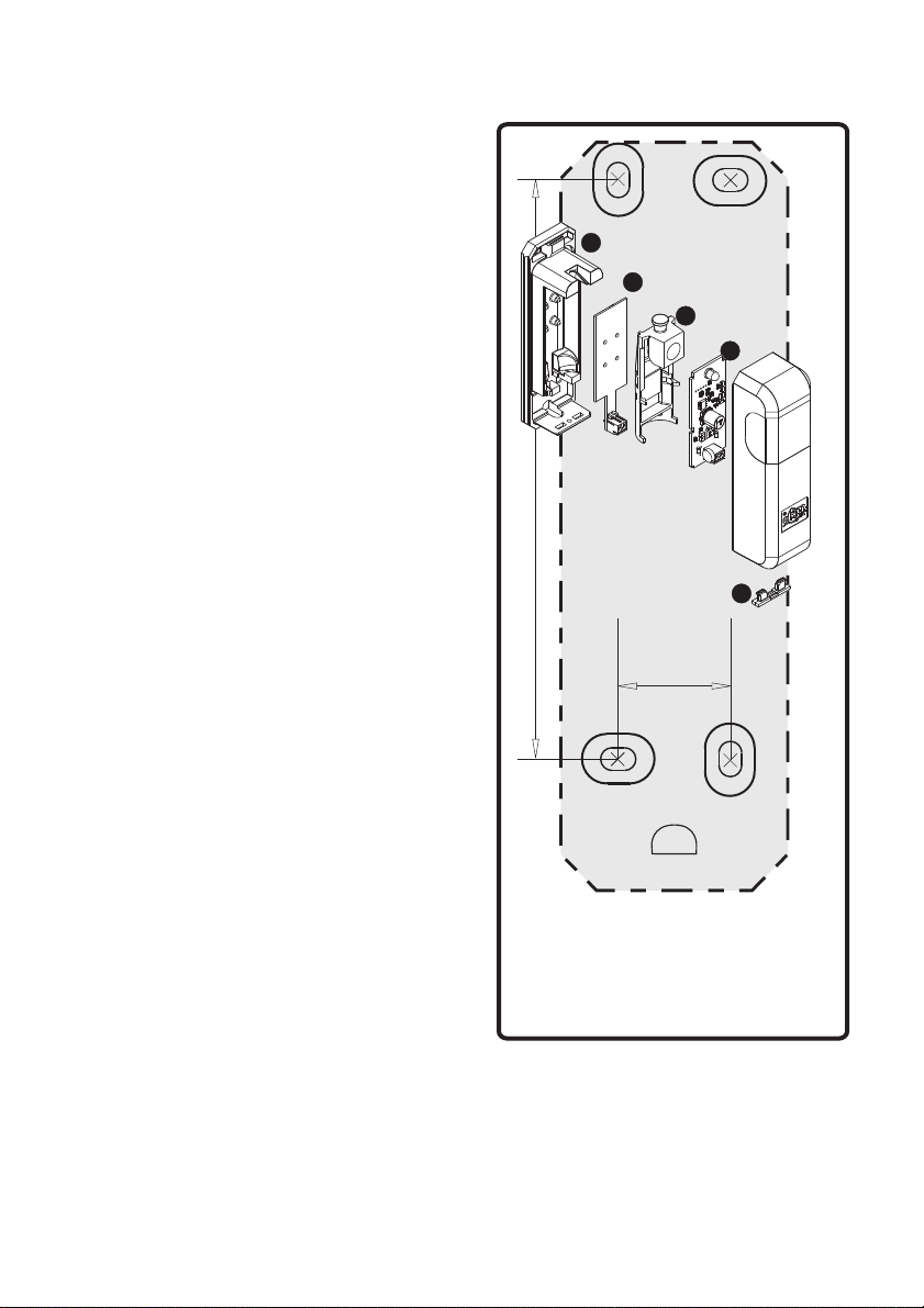
V S Z VERWENDEN IE DIESE EICHNUNG ALS ORLAGE
Legende:
1. Gehäusebasis (SLIM3 schwarz, SLIM3 ECO LED orange)
2. LED-Modul (Version SLIM3 ECO LED)
3. Elektrodenplatine mit Linse
4. Lichtschranke - Elektrodenplatine
5. Spritzwassergeschützter äußerer Schirm.
6. Befestigung des Schirms.
Abb. 1 Abstände der Befestigungslöcher
im Maßstab 1:1 mit Montagezeichnung.
18 mm
92 mm
1
2
3
4
5
6

Signalisierung
RX
PWR
*Unterbre
-cherbrücke
für
Lampenmodul
NC CNO 12-24V
AC/DC
LAMP
12-24V
AC/DC
LAMP
12-24V
AC/DC
12-24V
AC/DC
Wenn dasGerät, an das die Lampe angeschlossen ist, nicht über einen
eingebauten Unterbrecher verfügt, kann der eingebaute Impulsgeber
der Lampe aktiviert werden, indem eine Steckbrücke auf das LED-Modul
gesetzt wird.
*
Lampenbetriebsmodus
(LED-Version):
Steckbrücke
eingeschaltet
- Impulsbetrieb
Steckbrücke
entfernt
- Dauerbetrieb
*
4. ElektrischerAnschluss der Lichtschranke
Die Lichtschranke ist mit den Schalttafeln der Torautomaten verbunden. Es wird empfohlen,
die elektrische Installation und den Anschluss der Lichtschranke von einer qualifizierten
Persondurchführen zulassen. DerAnschlusserfolgtnach dem inAbb.2 gezeigtenSchemaund
nachder folgendenBeschreibung:
Schließen Sie die 12-24 V AC/DC-Stromversorgung an den Sender und an den Empfänger der
Lichtschranke an. Die PWR-LEDs an Sender und Empfänger sowie die RX-LED am Empfänger
solltenleuchten.
Bei Verwendung von Wechselstrom müssen Sender und Empfänger mit der gleichen Phase
(vondergleichenStromversorgung) versorgt werden.
Verbinden Sie den Signalausgang des Lichtschrankenempfängers (normalerweise NC
und C) mit dem entsprechenden Eingang des Bedienfeldes. Achten Sie besonders auf
die von der Steuertafel geforderteSteuerungsart (NC oder NO). Eine Standardlösung in
derTürautomation ist der Betrieb von optischenSensoreninNC-Konfiguration.
Empfänger RX
Beschreibungen
der Klemmenleisten
TX-Sender
Steuereinheit
Signalleistung
der Lichtschranke (NC)
Stromversorgung für Zubehör
12-24V AC/DC
Stromversorgung für
Signallampe12-24V AC/DC
STROMVERSORGUNG, Polarität unerheblich
STEUERSIGNAL
S STROMVERSORGUNG FÜR DIE IGNALLAMPE
TX-SenderEmpfänger RX
Abb. 2 Elektrischer Anschluss der Lichtschranke.
DE

5. ElektrischerAnschluss derSignalleuchten (VersionSLIM3 ECO LED)
Die LED-Lichtschranken SLIM3 ECO sind mit Signalisierungsmodulen ausgestattet. Die
Lampen sind für die Interaktion mit dem Meldeausgang der Zentrale der Torautomatik
bestimmt. Die LED-Module sollten an einen Meldeausgang mit einer Ausgangsspannung von
12..24V AC/DC angeschlossen werden. Die Module verfügen über einen eingebauten
Unterbrecher. Wenn das Gerät, an das die Lampe angeschlossen ist, nicht über einen
eingebauten Unterbrecher verfügt, kann der eingebaute Impulsgeber der Lampe aktiviert
werden, indem eine Steckbrücke auf das LED-Modul gesetzt wird. Ein Beispiel für einen
Lampenanschlussist indenAbbildung2dargestellt.
6.Abnahmetests
Nach dem Anschluss der Lichtschranke muss ein Test durchgeführt werden, d.h. die Reaktion
des Empfängers (RX) auf das Überschreiten der Lichtschranke muss überprüft werden.
Torautomatisierungssystememüssen gemäßEN 12453geprüft werden.
Test des Lichtschrankenpaares:
-SchließenSiedieStromversorgung nur anden Empfänger an undprüfenSie, ob dieRX-Diode
ausgeschaltetist.
- Schließen Sie auch die Stromversorgung an den Sender an und prüfen Sie, ob die RX-Diode
leuchtet.
- Verschieben Sie den Zylinder mit einem Durchmesser von 5 cm und einer Länge von 30 cm,
der die optische Achse zwischen Sender und Empfänger senkrecht kreuzt, zuerst in die Nähe
des Senders TX, dann in die Nähe des Empfängers RX und dann auf halbem Weg zwischen
beide. Die Lichtschranke sollte jedes Mal vom Standby-Zustand in den Alarmzustand
übergehen,was durchdas Erlöschender RX-Diodeerkennbar ist.
-Falls angeschlossen,überprüfenSiedie Funktionder Kontrollleuchten.

1.General information
A photocell consists of a transmitter and a receiver. Available in the SLIM3 ECO version and in
the SLIM3 ECO LED version equipped with a lamp module. Additional optical signaling serves
as a warning and makes it easier to locate the entrance in conditions of poor visibility. The
receiver has NC and NO type control contacts, the circuit of which is protected by an additional
relay.The photocell is designed to work in gate systemsas asafety elementworking outside.
2.Technical data
Basic parameters
•externaldimensions ofthe housing
(widthxdepth xheight): 37x36x120mm
•mountingmethod: surface-mounted, splash-proofhousing, IP-54
•casematerial: polycarbonate
•workingtemperature (min./max.): -20 °C/+55 °C
•weight: 80g
•guaranteedoperating range: 1-15m
•transmitterand receiver
powersupply: 12 ...24VAC/DC ±10%
•receivercurrent consumption: max.25mA
•transmittercurrent consumption: max.25mA
Signal lamp parameters (LED version)
•signallamp powersupply: 12 ...24VAC/DC ±10%
•powerconsumption: max. 150mA
•operatingmodes: continuous orpulsed, built-incircuitbreaker
•technology: LED
•shockand vibrationresistance: high
Executive elements
•contactoutputs
(type/ maximumload): NO orNC /1A (24VAC / DC)
Functionality
•adjustableviewing angle: 180° horizontally in the transmitter and receiver,
allows the installation of the photocell on a plane
parallelto thegate
•userinterface: hardware interface on two LEDs indicating power
connection and facilitating synchronization of the
transmitterbeam withthe receiver
•additionalprotection: the output system with an increased degree of safety
(in the event of damage, the photocell output always
goesinto theviolation state)
EN

3. Installation of the photocell
The transmitter and receiver should be mounted
40 - 60 cm above the ground. The distance
between the transmitter and receiver should not
be less than 1 m. The photocell has an angle of
vision adjustment both in the receiver and in the
transmitter. Coaxial assembly is not required,
only the maximum angles of rotation of the
electronic boards in the transmitter and receiver
housingsshould be takeninto account.Due tothe
photosensitive elements of the receiver, it is
recommended to mount the receiver on the less
sunny side. Both the transmitter and the receiver
of the photocell should be mounted vertically, the
terminal blocks and the moisture drainage holes
in the cover should be in the lower part of the
housing. Proper alignment of the transmitter and
receiver is facilitated by the RX diode, which
lights up when the transmitter beam reaches the
receiver. Each of the housings is attached to the
mounting surface with 2 (diagonally mounted) or
4screws includedin theset.
Do not install mirrors or reflective screens in the
photocell's area of operation, the receiver should
be installed on the less sunny side, if possible, the
photocell receiver should not be installed in a
place exposed to a strong source of extraneous
light, especially from fluorescent lamps, as this
may interfere with the barrier's operation. Be
careful not to contaminate the optical elements
ofthe transmitter/ receiverduring assembly.
USE THIS DRAWING AS A TEMPLATE
Legend:
1. housing base (SLIM2 ECO black SLIM3 ECO LED orange)
2. LED module (version SLIM3 ECO LED)
3. electronics board holder with a lens
4. electronics board of the photocell
5. splash-proof outer cover
6. fixing of the lampshade
Fig. 1 The spacing of the mounting holes
in the scale 1: 1, with the assembly drawing.
18 mm
92 mm
1
2
3
4
5
6

Signaling:
RX
PWR
*lamp
module
breaker
jumper
NC CNO 12-24V
AC/DC
LAMP
12-24V
AC/DC
LAMP
12-24V
AC/DC
12-24V
AC/DC
Fig. 2 Electrical diagram for connecting the photocell.
If the device to which the lamp is connected has no built-in circuit
breaker, you can start the pulser built in the lamps
by placing a jumper on the LED module.
*
Lamp operation mode
(LED version):
jumper on
- impulse mode
jumper off
- continuous
mode
*
4. Electrical connection of the photocell
The photocell works with the gate automation control units. It is recommended that the
electrical installation and connection of photocells made a person with appropriate
qualifications.The connection should be carried out in accordance with the diagram shown in
Fig.2 andas describedbelow:
Connect the power supply 12-24VAC / DC to the transmitter and the receiver of the photocell.
The PWR diodes in the transmitter and receiver and the RX diode in the receiver should be on.If
AC power is used, power the transmitter and receiver using the same phase (from one power
supply).Connect the signal output of the photocell receiver (usually NC and C) to the
corresponding input on the control unit. Pay special attention to the control method (NC or
NO) required in the control panel.The standard solution in gate automation is the operation of
opticalsensors inthe NCconfiguration.
Controller
photocell signal input (NC)
accessories power supply
output 12-24V AC/DC
signal lamp power supply
output 12-24V AC/DC
POWER SUPPLY, polarity irrelevant
CONTROL SIGNAL
SIGNAL LAMP POWER SUPPLY
transmitter - TXreceiver - RX
receiver - RX
terminals description
transmitter - TX
EN

5. Electrical connection of signal lamps (SLIM3 ECO LED version)
SLIM3 ECO LED photocells have signaling modules.The lamps are designed to work with the
signaling output of the gate automation control unit. LED modules should be connected to the
signaling output with an output voltage of 12..24VAC / DC.The modules have a built-in circuit
breaker. If the device to which the lamp is connected has no built-in circuit breaker, you can
start the pulser built in the lamps by placing a jumper on the LED module. An example of
connectingthe lampsis shownin figure2.
6.Acceptance tests
After connecting the photocell, perform a test, i.e. check the receiver's (RX) reaction to the
crossing of the light barrier. Gate automation systems must be tested in accordance with EN
12453.
Photocellpair test:
-connect thepower supplyto thereceiver onlyand checkif theRX diodeis off.
-also connectthe powersupply tothe transmitterand checkif theRX diodeis on.
- move a roller 5 cm in diameter and 30 cm long cutting the perpendicular optical axis between
the transmitter and receiver, first near theTX transmitter, then near the RX receiver, and then
halfway between them. Each time the photocell should switch from standby to alarm, which is
visibleby theRX diodegoing off.
-if connected,check theoperation ofsignal lamps.


DISPOSAL
Electrical or electronic devices cannot be
removed with everyday waste.The correct
recycling of devices gives the possibility of
keepingnatural resourcesof theEarthfor a
longer time and prevents the degradation
ofnaturalenvironment.
WARRANTY
The manufacturer DTM System provides
the devices that are operational and ready
for use. The warranty is granted for a
period of 30 months from the date of sale
by the manufacturer. The warranty period
i s d e t e r m i n e d b a s e d o n t h e
manufacturer's warranty seals identifying
the production batch, placed on each
product. To recognize the warranty, it is
necessary to present a sales document.
The manufacturer undertakes to repair the
device free of charge if there are defects
due to the manufacturer's fault during the
warranty period. The defective device
must be delivered to the place of purchase,
including a copy of the proof of purchase
and a brief, unambiguous description of
the damage. The cost of disassembly and
assemblyofthe deviceis borne bythe user.
The warranty does not cover batteries in
remote controls, any damage resulting
from i mproper use, unauthorized
adjustments, alterations and repairs, and
damage caused by lightning, overvoltage,
or short circuit of the power supply
network. The detailed terms and
conditions of granting a guarantee are
regulatedbyrelevantlegalacts.
ENTSORGUNG
Entsorgung der Elektrogeräte bzw.
Elektronik darf nicht in Rahmen der
Hau sha lts abf äll e erf olg en . E in e
sachgerechte Entsorgung des Gerätes
m a c h t e s m ö g l i c h , n a t ü r l i c h e
Erdressourcen länger aufrecht zu erhalten
s o w i e d e r U m w e l t z e r s t ö r u n g
vorzubeugen.
GARANTIEBEDINGUNGEN
Der Hersteller, DTM System, übergibt das
Gerät betriebsbereit und einsatzfähig. Die
Garantiezeit beträgt 30 Monate ab dem
Verkaufsdatum durch den Hersteller. Die
G a r a n t i e z e i t w i r d a n h a n d d e r
Garantiesiegel des Herstellers ermittelt,
die die Produktionscharge identifizieren,
die auf jedem Produkt angebracht ist. Zur
Übernahme der Garantie ist die Vorlage
eines Verkaufsbelegs erforderlich. Der
Hersteller verpflichtet sich, das Gerät
kostenlos zu reparieren, wenn während
der Garantiezeit Mängel auftreten, die auf
ein Ve rs ch uld en d es Herst el le rs
zurückzuführen sind. Das defekte Gerät
sollte unter Beifügung einer Kopie des
Kaufbelegs und einer kurzen, eindeutigen
Beschreibung des Schadens an die
Verkaufsstelle geschickt werden. Die
Kosten für die Demontage und Montage
des G eräts gehen zu Lasten des
Anwenders. Die Garantie erstreckt sich
nicht auf Batterien in Handsendern, auf
Schäden, die durch unsachgemäßen
G e b r a u c h , n i c h t a u t o r i s i e r t e
A n p a s s u n g e n , Ä n d e r u n g e n u n d
Reparaturen verursacht werden, sowie auf
Schäd en , di e du rch Bli tz sc hl ag,
Überspannung oder Kurzschluss im
Stromnetz entstehen. Die detaillierten
Garantiebedingungen werden durch die
geltendenGesetzegeregelt.
UTYLIZACJA
U r z ąd z e ńe l e k t r y c z n y c h l u b
elektronicznych nie można wyrzucać
razem z odpadami gospodarczymi.
Prawidłowa utylizacja urządzenia daje
możliwość zachowania naturalnych
zasobów Ziemi na dłużej i zapobiega
degradacjiśrodowiskanaturalnego.
WARUNKIGWARANCJI
Producent DTM System, przekazuje
urządzenia sprawne i gotowe do użytku.
Gwarancja udzielona jest na okres 30
miesięcy od daty sprzedaży przez
producenta. Okres gwarancji określany
jest na podstawie plomb gwarancyjnych
producenta identyfikujących partię
produkcyjną, umieszczanych na każdym
wyrobie. Do uznania gwarancji niezbędne
j e s t p r z e d s t a w i e n i e d o k u m e n t u
sprzedaży. Producent zobowiązuje siędo
bezpłatnej naprawy urządzenia, jeżeli w
okresie gwarancji wystąpiły wady z winy
producenta. Niesprawne urządzenie
należy dostarczyćdo miejsca zakupu,
załączając kopie dowodu zakupu i krótki,
jednoznaczny opis uszkodzenia. Koszt
demontażu i montażu urządzenia ponosi
użytkownik. Gwarancja nie obejmuje
baterii w pilotach, wszelkich uszkodzeń
powstałych w wyniku nieprawidłowego
użytkowania, samowolnych regulacji,
przeróbek i napraw oraz uszkodzeń
powstałych w wyniku wyładowania
atmosferycznego, przepięcia lub zwarcia
sieci zasilającej. Szczegółowe warunki
udzielania gwarancji regulująstosowne
aktyprawne.
D T M S y s t e m
niniejszym oświadcza,
że urządzenie j est
zgodne z dyrektywami 2014/30/UE,
2006/42/WE. Pełny tekst deklaracji
zgodności UE jest dostępny pod
adreseminternetowym.
DTM-System erklärt
hiermit, dass dasGerät
e n t s p r i c h t d e n
Richtlinien 2014/30/EU, 2006/42/EG.
Der vollständige Text der EU-
Konformitätserklärung ist unter der
Internetadresseabrufbar.
DTM System hereby
declares that the device
c o m p l i e s w i t h t h e
directives 2014/30/EU, 2006/42/EC.
The full text of the EU declaration of
conformity is available at the
internetaddress.
DTM System, ul. Brzeska 7, 85-145 Bydgoszcz, Polska, tel. +48 52 340 15 83, www.dtm.pl
Table of contents
Languages:
Popular Outdoor Light manuals by other brands

TOOLCRAFT
TOOLCRAFT 2482483 operating instructions

Zafferano
Zafferano Poldina LD0286B3 Instructions for use

Kanlux
Kanlux FL SOLNAR SLR 8W instruction manual

Global Light & Power LCC
Global Light & Power LCC ZIYA 11 manual

Powerfix Profi
Powerfix Profi HG03497A Operation and safety notes

LIGMAN
LIGMAN MI-50384 Installation and service manual