manuals.online logo
Brands
  1. Home
  2. •
  3. Brands
  4. •
  5. BEGA
  6. •
  7. Outdoor Light
  8. •
  9. BEGA 84 429 Manual

BEGA 84 429 Manual

Other BEGA Outdoor Light manuals

BEGA 84 760 User manual

BEGA

BEGA 84 760 User manual

BEGA 84 423 User manual

BEGA

BEGA 84 423 User manual

BEGA 84 730 User manual

BEGA

BEGA 84 730 User manual

BEGA 77 008 Manual

BEGA

BEGA 77 008 Manual

BEGA 77 011 User manual

BEGA

BEGA 77 011 User manual

BEGA 7723 User manual

BEGA

BEGA 7723 User manual

BEGA 33 200 Manual

BEGA

BEGA 33 200 Manual

BEGA 33 162 Series User manual

BEGA

BEGA 33 162 Series User manual

BEGA 24 358 Manual

BEGA

BEGA 24 358 Manual

BEGA 84 427 User manual

BEGA

BEGA 84 427 User manual

BEGA 33 386 User manual

BEGA

BEGA 33 386 User manual

BEGA 71 128 Manual

BEGA

BEGA 71 128 Manual

BEGA 33 242 User manual

BEGA

BEGA 33 242 User manual

BEGA 24 217 Manual

BEGA

BEGA 24 217 Manual

BEGA 85 046 User manual

BEGA

BEGA 85 046 User manual

BEGA 84065 Manual

BEGA

BEGA 84065 Manual

BEGA 8450 User manual

BEGA

BEGA 8450 User manual

BEGA 77 138 User manual

BEGA

BEGA 77 138 User manual

BEGA 22 202 Manual

BEGA

BEGA 22 202 Manual

BEGA 7264 User manual

BEGA

BEGA 7264 User manual

BEGA 84 242 Manual

BEGA

BEGA 84 242 Manual

BEGA 77 911 Manual

BEGA

BEGA 77 911 Manual

BEGA 84 667 User manual

BEGA

BEGA 84 667 User manual

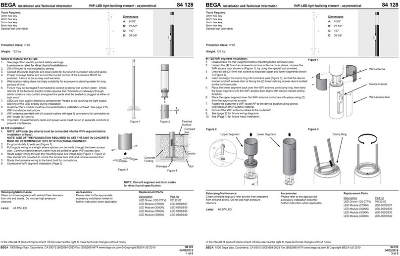
BEGA 84 128 Manual

BEGA

BEGA 84 128 Manual

Popular Outdoor Light manuals by other brands

Kichler Lighting HELEN 37536 instructions

Kichler Lighting

Kichler Lighting HELEN 37536 instructions

Thorn OXANE L installation instructions

Thorn

Thorn OXANE L installation instructions

esotec Solar Globe Light multicolor 20 operating instructions

esotec

esotec Solar Globe Light multicolor 20 operating instructions

mitzi HL200201 ELLIS Assembly and mounting instructions

mitzi

mitzi HL200201 ELLIS Assembly and mounting instructions

HEPER TILA S AFX 3 Module Installation & maintenance instructions

HEPER

HEPER TILA S AFX 3 Module Installation & maintenance instructions

Designplan TRON 180 installation instructions

Designplan

Designplan TRON 180 installation instructions

Sealey LED37 instructions

Sealey

Sealey LED37 instructions

nordlux VEJERS Mounting instruction

nordlux

nordlux VEJERS Mounting instruction

SImx ELITE LED LHTC637 installation instructions

SImx

SImx ELITE LED LHTC637 installation instructions

GEV CAROLINE 10833 manual

GEV

GEV CAROLINE 10833 manual

WE-EF PFL540 LED Installation and maintenance instructions

WE-EF

WE-EF PFL540 LED Installation and maintenance instructions

HEPER DOGO Side LW6048.585-US Installation & maintenance instructions

HEPER

HEPER DOGO Side LW6048.585-US Installation & maintenance instructions

HEPER LW8034.003-US Installation & maintenance instructions

HEPER

HEPER LW8034.003-US Installation & maintenance instructions

HEPER MINIMO Installation & maintenance instructions

HEPER

HEPER MINIMO Installation & maintenance instructions

LIGMAN BAMBOO 3 installation manual

LIGMAN

LIGMAN BAMBOO 3 installation manual

Maretti TUBE CUBE WALL 14.4998.04 quick start guide

Maretti

Maretti TUBE CUBE WALL 14.4998.04 quick start guide

Maxim Lighting Carriage House VX 40428WGOB installation instructions

Maxim Lighting

Maxim Lighting Carriage House VX 40428WGOB installation instructions

urban ambiance UQL1273 installation instructions

urban ambiance

urban ambiance UQL1273 installation instructions

manuals.online logo
manuals.online logoBrands
  • About & Mission
  • Contact us
  • Privacy Policy
  • Terms and Conditions

Copyright 2025 Manuals.Online. All Rights Reserved.

Installation and Technical Information
BEGA
Due to the dynamic nature of lighting products and the associated technologies, luminaire data on this sheet is subject to change at the discretion of BEGA North America. For the most current technical data, please refer to bega-us.com
BEGA 1000 Bega Way, Carpinteria, CA 93013 (805)684-0533 © copyright BEGA 2023
Figure 1:
Figure 3:
Figure 2:
Overview:
LED Watts: 3.9W
System Watts: 5W
Controllability: 0-10V dimmable
Weight: 8.2 lbs.
Protection Class: IP65
Tools Required:
• 3mm hex head screwdriver
• 4mm hex head screwdriver
• 1/4” drill bit
• Adjustable wrench
Bollard - hardscape base - 360° 84 429
Dimensions
A: 4-3/8
B: 28-5/8
Maintenance:
Clean regularly with solvent-free cleaner
removing dirt and debris. Do not use high
pressure cleaners.
Replacement Parts
See label inside of xture for LED replacement
part number.
Consult factory for all other replacement
components.
Accessories
Please refer to the appropriate accessory installation
sheet for further instruction when applicable.
Updated: 10/10/23
84 429 1 of 2
Notice to Installer:
1. See page 2 for specic product safety warnings.
2. Fixture may be damaged if connected to conduit systems that contain water- Article
300-5G of the National Electric Code requires that “Conduits or race ways through
which moisture may contact energized live parts shall be sealed or plugged at either
or both ends.”
3. Anchorage can be installed in concrete.
4. It is recommended that when installing in planting areas the bollard base be slightly
elevated to avoid prolonged submersion during heavy rains.
5. Wet location listing does not imply suitability for exposure to standing water for
long periods of time. Proper drainage must be provided. Failure to do so may void
warranty.
6. It is not necessary to remove bollard head or open driver box during installation. Any
tampering with xture head or driver box could result in failure and void warranty.
Installation: Luminaire
1. Provide means to bring supply wiring to the conduit entry location in accordance with
local codes.
2. Disassemble mounting base from main bollard. Carefully remove the mounting base
from the bollard tube by loosening (2) 3mm hex head set screws near the base of
the bollard. See Figures 1 and 2.
3. Driver box is connected to the bollard head using 4’ of cable. Warning: Do not pull on
or remove cable from head or driver box.
4. To remove driver box from mounting base, loosen (1) 4mm hex head screw at the
top of the mounting base. See Figure 3
5. Place mounting base on surface and mark drill locations, then remove mounting
base and drill holes using 1/4” drill bit.
6. Insert anchors into 1/4” holes.
7. Align mounting base with anchors, and pull supply wires through mounting base.
Make sure base is level - use washers as spacers underneath if necessary.
8. Use adjustable wrench on included anchor bolts nuts to tighten mounting base onto
anchorage.
9. Replace driver box by sliding rail into mating part on mounting base. Secure into
place by tightening (1) 4mm hex head screw. See Figure 3.Make bollard and supply
wiring connections. Connections can be made in bollard tube, do not open driver
box:
MAIN VOLTAGE SUPPLY WIRE TO BLACK DRIVER BOX WIRE;
NEUTRAL (COMMON) SUPPLY WIRE TO WHITE DRIVER BOX WIRE;
GREEN GROUND WIRE TO GREEN DRIVER BOX WIRE.
0-10V Dimming (if applicable):
DIMMING CONTROL WIRE (+) TO POSITIVE DRIVER BOX DIM WIRE
DIMMING CONTROL WIRE (-) TO NEGATIVE DRIVER BOX DIM WIRE
10. Replace bollard tube over mounting base, pushing wiring connections up into tube.
Orient tube and head as needed and tighten into place using (2) 3mm hex head set
screws at base of bollard tube. See Figures 1 and 2.
Mounting Base
Driver Box
Bollard Tube
Bollard Head
4mm Hex Screw
Installation and Technical Information
BEGA
Due to the dynamic nature of lighting products and the associated technologies, luminaire data on this sheet is subject to change at the discretion of BEGA North America. For the most current technical data, please refer to bega-us.com
BEGA 1000 Bega Way, Carpinteria, CA 93013 (805)684-0533 © copyright BEGA 2023
Product Safety Warnings:
THIS PRODUCT MUST BE INSTALLED IN ACCORDANCE WITH THE APPLICABLE INSTALLATION
CODE BY A PERSON FAMILIAR WITH THE CONSTRUCTION AND OPERATION OF THE PRODUCT
AND THE HAZARDS INVOLVED. SUITABLE FOR MOUNTING WITHIN 1.2 m (4ft) OF THE GROUND.
SUITABLE FOR WET LOCATIONS.
MIN 60°C SUPPLY CONDUCTORS.
CE PRODUIT DOIT ÊTRE INSTALLÉ SELON LE CODE D’INSTALLATION PERTINENT, PAR UNE
PERSONNE QUI CONNAÎT BIEN LE PRODUIT ET SON FONCTIONNEMENT AINSI QUE LES RISQUES
INHÉRENTS. PEUT ÊTRE INSTALLÉ À MOINS DE 1,2 m (4 pi) DU SOL.
CONVIENT AUX EMPLACEMENTS MOUILLÉS.
LES FILS D’ALIMENTATION 60°C MIN.
Updated: 10/10/23
2 of 2
84 429
Bollard - hardscape base - 360° 84 429