DTronics DT-800 User manual

DTRONICS
DT-800
MANUAL
DT-800
User’s Manual

DTRONICS
DT-800
MANUAL
Index
Document revisions ............................................................................3
1Setup .................................................................................................4
Intended use .......................................................................................4
What is included .................................................................................4
Installation ..........................................................................................4
2Operation ..........................................................................................5
Memory ..............................................................................................5
Usb ......................................................................................................5
Firmware version ................................................................................5
Firmware version update ....................................................................5
3Panel description ...............................................................................7
4Specifications.....................................................................................8

DTRONICS
DT-800
MANUAL
Document revisions
Date
Doc. revision
FW version
Change
25-04-2020
R1.0
V1.0
Initial document

DTRONICS
DT-800
MANUAL
1Setup
Intended use
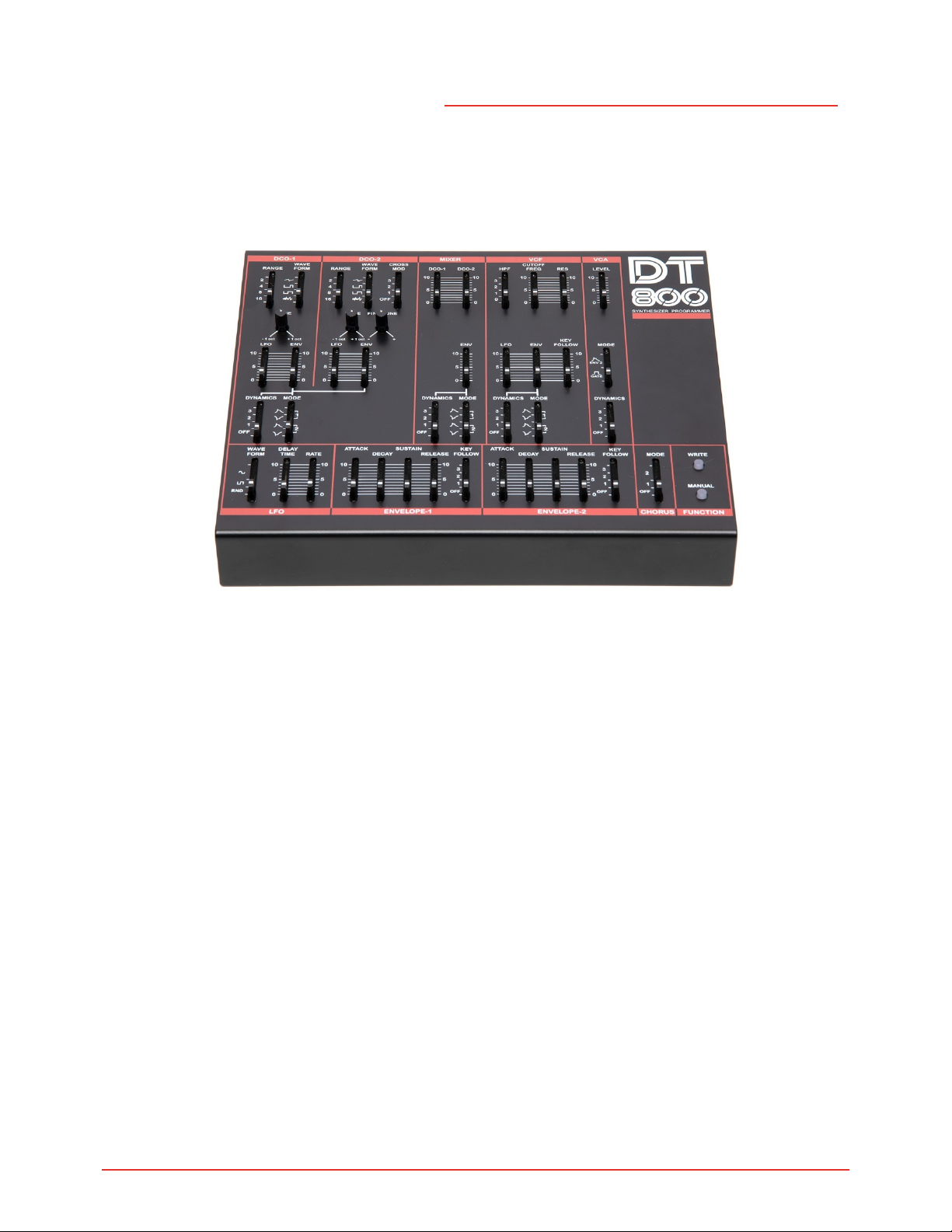
The DT-800 is intended to create new sounds for your synthesizer.
The DT-800 is a programmer for the JX-8P, MKS-70 and the JX-10 synthesizers.
What is included
Please ensure that your DT-800 includes the following:
•DT-800 Programmer
•USB cable
•6pin Male-Male MIDI Cable
Installation
Installation of the programmer to the synthesizer is simple and requires no tools. .
1. Make sure that the synthesizer is turned off
2. Connect the DIN jack on the programmer and the Programmer Input jack
on the rear panel of the synthesizer with the DIN cord (6p)
3. Turn on the synthesizer.
The synthesizer supplies power to the DT-800
4. When the DT800 is turned on, the Red LEDs will go on and off, showing
everything is ok.
5. Push the Manual button , then synthesize your own sound
The DT800 has no sound source itself, therefore no sound is obtained unless
connected to the synthesizer.
The DT800 can edit the preset patches of the synthesizer.

DTRONICS
DT-800
MANUAL
2Operation
By default the MANUAL led will be active on the DT-800 while turned ON.
Memory
The sound you have synthesized with the DT-800 can be written into the
synthesizer.
Follow the instructions in the owner’s manual of each synthesizer.
Usb
The Usb connection on the DT-800 can be used to update the firmware when
available.
Firmware version
When starting up the DT-800 the firmware version is displayed using the WRITE
and MANUAL led located on the bottom right of the programmer. The version is
calculated by the number of times the two leds are flashing. The version number
can be displayed like: <WRITE>.<MANUAL>
Example: When the WRITE led flashes 2 times and the MANUAL led flashes 3
times the firmware version is 2.3
Firmware version update
To use the bootloader in the DT-800 to update the firmware in the DT-800 follow
the following steps:
1. Press the WRITE button
2. Turn on the DT-800

DTRONICS
DT-800
MANUAL
3. WRITE en MANUAL leds will burn to indicate bootloader mode.
4. Release WRITE button
5. Send firmware file with SysEx tool. (for example MIDI-OX)
6. During the upload the MANUAL led will flash.
7. When the upload is completed the DT-800 will reboot.

DTRONICS
DT-800
MANUAL
3Panel description
1. DCO-1 Range Selector
2. DCO-1 Wave form Selector
3. DCO-2 Range Selector
4. DCO-2 Wave form Selector
5. DCO-2 Cross Mod. selector
6. DCO-1 Mixer Level
7. DCO-2 Mixer Level
8. High Pass Filter Selector
9. VCF Cutoff Frequency
10. VCF Resonance
11. VCA Level
12. Tune
13. Tune
14. Fine Tune
15. LFO Modulation
16. Envelope modulation
17. LFO Modulation
18. Envelope Modulation
19. Envelope Modulation
20. LFO Modulation
21. Envelope Modulation
22. Key follow
23. VCA Mode Selector
24. Dynamics selector
25. Envelope Mode Selector
26. Dynamics selector
27. Envelope Mode Selector
28. Dynamics selector
29. Envelope Mode Selector
30. Dynamics selector
31. LFO Waveform Selector
32. LFO Delay Time
33. LFO Rate
34. Envelope 1 Attack
35. Envelope 1 Decay
36. Envelope 1 Sustain
37. Envelope 1 Release
38. Envelope 1 Key Follow selector
39. Envelope 2 Attack
40. Envelope 2 Decay
41. Envelope 2 Sustain
42. Envelope 2 Release
43. Envelope 2 Key Follow selector
44. Chorus Mode Selector
45. Write Button
46. Manual Button

DTRONICS
DT-800
MANUAL
4Specifications
[Programmer PG-800]
DCO-1
Range (2’, 4' , 8' , 16')
Waveform ( )
Tune (+/- 1 oct)
Frequency Modulation (LFO, ENV)
Dynamics Selector
Envelope Mode
DCO-2
Range (2’, 4' , 8' , 16')
Waveform ( )
Tune (+/- 1 oct)
Frequency Modulation (LFO, ENV)
Dynamics Selector
Envelope Mode
Cross Modulation
Fine Tune
Mixer
DCO-1, DCO-2 Level
Envelope Modulation
Dynamics Selector
Envelope Mode
VCF
HPF (High-pass Filter)
Cutoff Frequency
Resonance
LFO Modulation
Envelope Modulation
Key Follow
Dynamics Selector
Envelope Mode
VCA
Mode (ENV 2, Gate)
Level
Dynamics Selector
VCA
Mode (ENV 2, Gate)
Level
Dynamics Selector
ENV
Attack Time
Decay Time
Sustain Level
Release Time
Key Follow
LFO
Waveform ( )
Delay Time
Rate
Chorus
Mode Selector
Function
Manual button
Write Button
Rear Panel
jack DIN6P
Dimensions DT-800 240(W) 210(D) x 45(H)mm
Weight DT-800 0.85 kg
Dimensions Box 330(W) 220(D) x 70(H)mm
Total weight box 1.088 kg
Power consumption USB or DIN: 60mA
Accessories
DIN cord (DIN6P)
USB Cable
Specifications are subject to changes without notice

DTRONICS
DT-800
MANUAL
Table of contents
Other DTronics Motherboard manuals