DTS PROFILO 500 User manual

※本型号机型在尚未进行重大改版之前,配件可能进行调整,外观、型号可能稍有不同。DTS保留配件内容更改权,并不另行通知。
Before this model has being significantly changed to another new version, the parts, appearance and the existing version can be developed and
modified that would lead to a slight difference from the original design. DTS reserve ALL the Rights of change of parts and contents WITHOUT
specified notification.
DTS 500
DTS 500
®
Instruction Manual
规格参数
全长:810mm
全高:295mm
主旋翼直径:Φ950mm
尾旋翼直径:Φ205mm
总重量:约1800克
DTS 1320Kv 无刷马达
DTS 6S 75A 调速器
MICROBEAST 三轴陀螺
GWY S48P 倾斜盘伺服器*3pcs
GWY S48T 尾伺服器*1pcs
FK主旋翼
Specifications
Length:810mm
Height:295mm
Main Rotor Diameter:Φ950mm
Tail Rotor Diameter:Φ205mm
Flying Weight:Approximately 1800g
DTS 1320Kv brushless motor
DTS 6S 75A ESC
MICROBEAST 3-axis Gyro
GWY S48P Swash Servos*3
GWY S48T Tail Servos*1
FK Main Blade

2
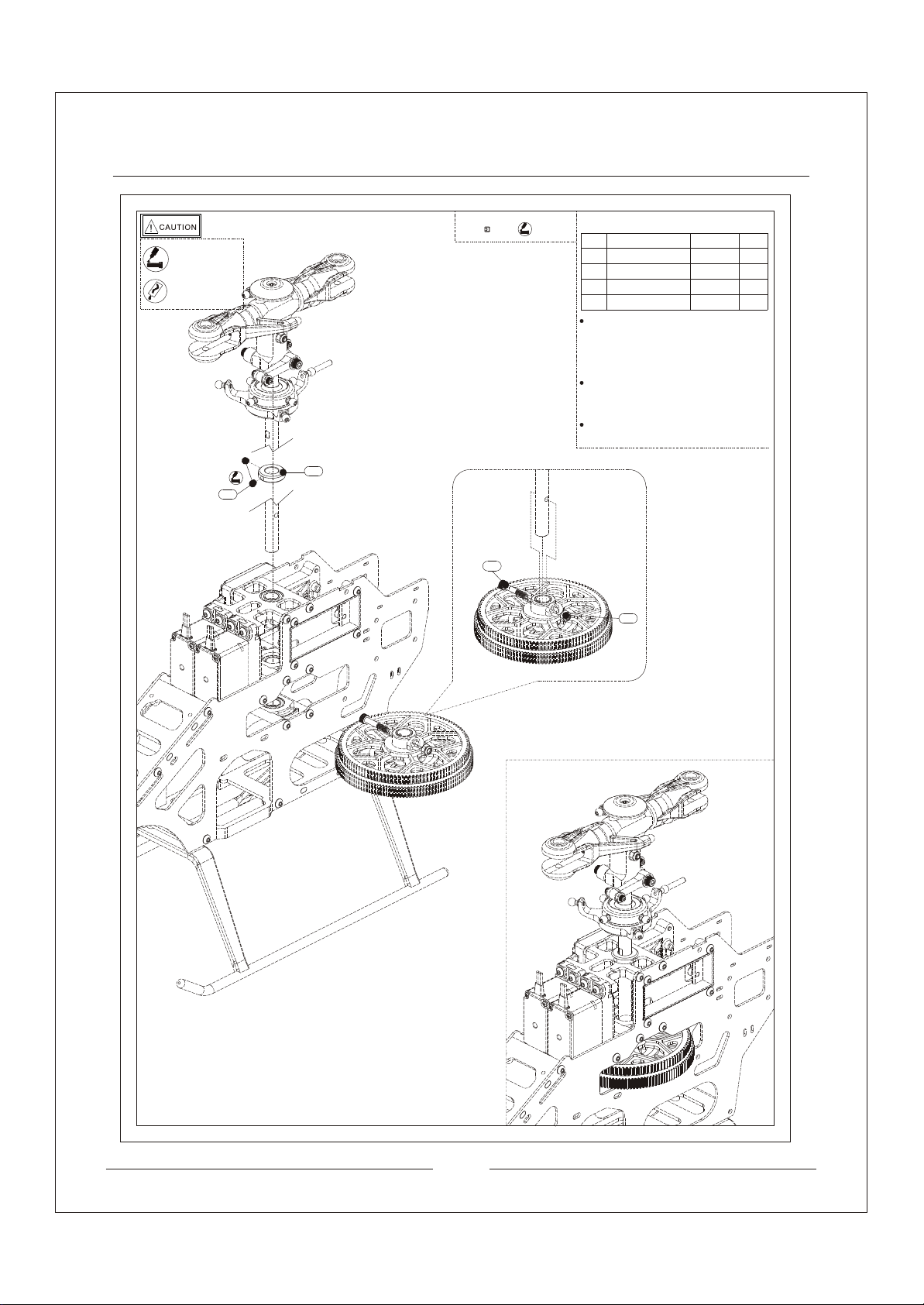
Warning Label Legend
Safety Precautions and Warning
Pre-flight check
Statement
FORBIDDEN
FORBIDDEN
Do not attempt under any circumstances.
WARNING
Mishandling due to failure to follow these instructions may result in danage or injury.
CAUTION
RC helicopter is controlled by radio signals. It may be interfered by other radio signals during operation.
These interference may cause the helicopter lose control.
Mishandling due to failure to follow these instructions may result in danger.
WARNING
An RC Helicopter is not a toy! For avoiding accidents and damage, please operate the helicopter properly.
Since the consumer have purchased the helicopter, they should take all the risks in the usage. To ensure
your safety, if you are a beginner, you are recommended to consult or get assistance from experienced RC
modelers or your local hobby stores.
You should buy the authorized DTS accessories when you choosing the accessories. Otherwise, some
RC functions may not be matched or function unproperly.
Please keep instruction manual to properly maintain your model.
1.An RC Model is not a toy! Improper operation or misuse may lead to serious damage or loss. It is
prohibited for children under 14 years to operate this product.
2.Keep it away from high temperature environment and corrosive chemicals for storage and flight.
(the operation temperature: from:-10℃to 50℃)
3.If you are not an experienced pilot or have not flown this type of model before, we recommend that
you get assistance of an experienced pilot for your first flights. Please avoid flying with other RC models
with same frequency.
4.Please choose a open flight area and use the training gear set for your first fight in order to minimize
your loss due to control mistakes.
1.To avoid the loss of the property of others, please keep away from high tension power lines, high
buildings or any other obstacles while flying!
2.Keep away from crowds in case of accidents!
3.Do NOT operate in rain, thunder, storms, lighting, strong wind or any other bad weathers to ensure
your and the helicopter’s safety!
4.Please avoid using in a bathroom or a rainy day to prevent moisture or water vapor from entering the
helicopter inside which may lead mechanical or electronic components malfunction and cause unex-
pected accidents!
5.Do Not re-equip, upgrade or repair your helicopter with the accessories outside the DTS parts catalog
in order to ensure the safety of the model structure!
6.Keep people and objects away from the spinning unit and parts in case of damage or injury!
1.Please make sure the helicopter frequency will not interfered with others before every flight.
2.You should confirm the batteries of your transmitter and helicopter are fully charged before every flight
and your first flight.
3.Both the throttle stick (left-hand stick) and throttle trim MUST be in their lowest position before every
flight. Each time before your flight, you must ALWAYS turn on the transmitter power first before con-
necting the flight battery to the receiver. After your flight, you should disconnect the flight battery from
the receiver before turn off the transmitter.
4.Please make sure that every servos function properly with correct directions after powering on.
5.Make sure every connection of pushrods is proper and the helicopter battery placed in fixed position.

Foreword
Thank you for choosing DTS’s product. For better understanding and usage of DTS500, please read the
manual carefully before installation and operation. For your convenience of adjustment, maintenance and
other operation, please keep the manual in a proper manner. For further information, please visit Zonda
Hobby official website: http://www.zondahobby.com
Table of contents
3
DTS 500
Equipment you need
Rotor Housing Assemble Procedure
Frame Assemble Procedure
Power System Assemble Procedure
Tail System Assemble Procedure
Transmitter Setting Module
MICROBEAST 3 Axis Gyro Parameter Setting
Pre-Flight Controls Test
Exploded View
Spare Parts List
4
5
7
11
12
19
21
22
25
27

Equipment you need
4
Transimitter and Electronic Device
Tools
1 Electronic Pitch Gauge
2 Battery Voltage Detector
3 Knife
4 Phillips Screwdriver
5 Hex Screwdriver
6 Needle Nose Pliers
7 Lubricants
8 Instant Glue
Transmitter Receiver Charger Li-Po Battery
● 6S 22.2V 2800-3200mAh
Li-Po battery capable of 30C
or greater discharge rates
● 6-channel (or greater)
micro receiver ●Li-Po compatible charger
(2~6 cells)
● 6-channel (or greater) transmitter

Rotor HousingAssembleProcedure
5
10.5
No
009
010
Description
Step Washer
Damper Ring
013
012
014
015
Hexagon Socket
Head Screw
Spindle
Fastener M3
Linkage Ball
Qty
need
2pcs
014
013
012
005 015
006
003 004
002 008 009 010
017
006
008
006
004
005
003
002
017
Six Socket Head Screw
Spacer
Trust Bearing
Washer
Bearing 5* 10*4.5
8* 11*0.5
5* 10*4
3* 7*0.8
M3*10
5* 9.5*1.5
4.5* 10*5
Blade Grips
5*67.5
2pcs
2pcs
4pcs
2pcs
2pcs
2pcs
2pcs
2pcs
1pcs
1pcs
M3*8 1pcs
S 4.75*L4 2pcs
012
002
Make sure thehead of spindles
are same size andsymmetric.
Complete isetup ofrotor housing
Specification
M3*18Cap Screw
051
033
011 1pcs
1pcs
1pcs
M3
033
Main Shaft 8*156.5
Complete setup
diagram of rotor
housing
Install the spacer intothe rotor housing properly.
Install the damper ring into the rotor housing properly.
The head of spindlesmust be same size.
Paste necessary amount ofthread-locking fiuld
to the scew oncentre hub cap.
Check the rotor housingafter the installation. No
spare space is allowand choke when rotating.
Paste necessary amount of thread-locking fiuld
to the M3*10.
Paste little amount of lubricants bwhen installing
bearing. Notice the setupdirection.
Setup the trust bearinginside the blade gripspr-
operly. Makesure the bearing rotatesmoothly.
Setup the step washerin correct direction.
Plug the main shaftinto the rotor housing.
(Into the correct position)
Screw must pass throughthe rotor housing
and main shaft anduse M3 screw tofasten
them.
IN
OUT
AA
AA
051 011
Apply amount ofT43
thread-locking fiuld
Apply little amount lubricants
Apply little amount
lubricants
No Description Qty
need
Specification
018 Rotor Housing 1pcs
Centre Hub Cap
018
Nylon Lock Nut

6
Install the trust bearing inside the washout
control arm and should not be missed. Make
sure the bearing rotate smoothly.
Install the washout control arm bearing
inside the washout control arm. The expos-
ure parts should be same size.
Install the flange bearing inside the washout
control arm. Make sure the bearing rotate
smoothly.
Washout control arm link and washout contr-
ol arm should be fastened. Paste necessary
amount of thread-locking fiuld during the in
stallation.
Make sure the washout control arms move
smoothly after the complete installation
Install the swashplate based on the left
diagram. Lock the washout control arm
link by the linkage ball of the swashplate.
3* 6*2.5
Washout Control Arm
3* 5.5*1.35
3* 5.5*0.55
2* 5*2.5
Flange Bearings
Washout Control
Arm Link
Step Washer M2*5
Six Socket Head Screw
3.5*5*M2
Washout Spacer
011
025
2pcs
2pcs
4pcs
4pcs
4pcs
2pcs
2pcs
2pcs
011
021
023
022
024
025
4pcs
028
027
026
Pan Head Screw M3*18
Swashplate
029 1pcs
Complete setup diagram
Apply amount ofT43
thread-locking fiuld
Apply little amount lubricants
No Description Qty
need
Specification
No Description Qty
need
Specification
Step Washer
Flange Bearings
025
026
027
028
024011
023
021
022

Frame AssembleProcedure
7
Install the main shaft hubs, bottom tray,
battery tray inside the main frame.
Install the main shaft retaining collars into
the plastic main shaft hubs.
Paste necessary amount of thread-locking
fiuld to theupper main shaft.
Make sure all thescews are locked and no
loose is allowed.
060
062
1pcs
048
043
040
041
039
037 24pcs
2pcs
2pcs
1pcs
2pcs
4pcs
1pcs
039
062
041
040
060
043
048
037
043
034
X2
Bearing installed correctly
Pen Head Philips Screw
ST3*10
Main Frame
Servo Hub
Upper Bearing Block Set
Lower Bearing Block Set
BottomTray
BatteryTray
034 3pcs
Main Shaft Retaining
Collar 8* 14*4
M3*10
Setup diagram of main shaft
048
Complete setup diagram
Apply amount ofT43
thread-locking fiuld
Apply little amount lubricants
No Description Qty
need
Specification
Pan Head Screw

8
Use two M3*8 screws to lock the servo mo-
unting rod to the mainframe. Paste necessary
amount of thread-locking fiuld during the
installation.
Use pen head philips screw install the final
servo to the right frame servo hub.
Install the servos with the servo mounting rod
into the servo hub. Paste necessary amount
of thread-locking fiuld during the installation.
Install the rubber pads to all the servos first.
Then use pen head philips screw to fix the
servos into the servo mounting rod.
Lock the landing skid by pen head philips
screw.
Spacer 6pcs
120
048 6pcs
M3*12
Pen Head Philips Screw
119 2pcs
Pen Head Philips Screw
M3*8
119
048
Rubber pad
Hexagon Flat Head Screw
ST2.6*5
One Way Bearing Shaft
Gear Hub
133T
Main Gear
10* 14*0.8
Washer
ST3*10
Pen Head Philips Screw
Servo Mounting Rod
108T
Main Tail Drive Gear
1pcs
5* 10*4
045
4pcs
037
Servo: S48P
038
055
048
044
120
037
119
119
055
056 5pcs
054
052
044
050
4.5* 10*5
3pcs
1pcs
10pcs
1pcs
1pcs
1pcs
056
055
054
050
052
064
037
064
037 4pcs
1pcs
Pen Head Philips
Screw ST3*10
Landing Skid
Apply amount
of T43 thread-
locking fiuld
Apply little am-
ount lubricants
No Description Qty
need
Specification
No Description Qty
need
Specification
045
038
048
120

9
Install the main shaftretaining collar into the
main shaft. Alignthe holes from mainshaft
and gear and fixthem by the M3*18screw.
Don't apply too muchforce when fastening
the screws or theywill be damaged aswell
as the parts.
Pull up the rotorhousing tightly.Fasten the
retaining collar to themain shaft retaining
collar surface. Use M3*3kimi screw to lock
them and pasted withthread-locking fiuld.
After the complete installation,make sure
the rotor housing movessmoothly.
032
031 2pcs
1pcs
011 1pcs
032
031
011
051
051 1pcs
Main Shaft Retaining
Collar
M3*3mm
Kimi Screw
Nylon Lock Nut M3
Pen Head Philips
Screw M3*18
Complete setup diagram
Apply amount
of T43 thread-
locking fiuld
Apply little am-
ount lubricants
No Description Qty
need
Specification

10
Use M*12 kimi screwto fasten the canopy
mount rod and theanti rotation bracket onto
the main frame.
The bottom right diagramshows the complete
installation.
2pcs
035
1pcs
2pcs
036
042
Complete Installation
035 036 042
Anti Rotation Bracket
Canopy Mount Rod
Kimi Screw M3*12
Apply amount ofT43
thread-locking fiuld
Apply little amount lubricants
No Description Qty
need
Specification

Power SystemAssembleProcedure
11
032
Use kimi screws to fix the pinion gear onto
the motor shaft and pasted with thread-locking
fiuld.
Use four M3*10 screws to install the motor
mount onto the motor. Past with thread-locking
fiuld and do not miss the spacers during the in
stallation.
Finally,use four M3*10 screws to install the
motor into the main frame. Make sure the
distance between the pinion gear and the
main gear is 0.1mm. The rotation of main gear
and pinion gear should be smooth.
The bottom right diagram shows the complete
installation.
19.2
003
059
002
058
057
032
003 6pcs
2pcs
002 6pcs
057
058
059
002
003
Complete Installation
Diagram
Kimi Screw M3*3
M3*10
Spacer 3* 7*0.8
Pinion Gear 14
Brushless Motor 1320KV
Upper Bearing Block Set
1pcs
1pcs
1pcs
Apply amount
of T43 thread-
locking fiuld
Apply little am-
ount lubricants
No Description Qty
need
Specification
Pan Head Screw

Tail SystemAssembleProcedure
12
Install the pushrods to the fuselage as the
left diagram shown.
10pcs
019
Based on the left diagram, install the ball
links with the pushrod. The size and the
angle should be installed correctly.
PushrodA*2
Pushrod B *1
Pushrod C *2
Pushrod A
Pushrod C
Pushrod B
Use M2*5 screw to lock the trust bearing,
tail rotor blade grip, spacers, bearing on
the tail rotor hub. Paste necessary amount
of thread-locking fiuld and lubricants to the
screw heads and bearing respectively.
Use M3*18 screw and lock nut to lock the
tail rotor blade gripto the tail rotor hub. The
direction of the tail rotor blade should be
installed as diagram shown.
Install the linkage ball to the tail rotor blade
grip. After installation, there is no choke in
the tail rotor blade grip. Make sure the
distance between the tail rotor blade grip
and the tail rotor hub is within 0.2mm.
Install the tail rotor pitch control to the
linkage balls of the tail rotor blade grip
as left diagram shown.
Tail Rotor
Pitch Control
Factory installed
OUT
IN
3pcs
2pcs
020
030
030 019
020
Ball Link
Pushrod
Pushrod M2.3*32
M2.3*36
025
096
097
011 051
098
071
099
094
095
025 2pcs
011 2pcs
094
2pcs
051
1pcs
4pcs
071
2pcs
095
099 2pcs
098 2pcs
2pcs
097
096 2pcs
Tail Rotor Hub
Spacer 2* 5*0.5
Bearing
Spacer
F3-8M
6.5* 8*0.2
Tail Rotor Blade Grip
Linkage Ball S 4.75*L3
Pen Head Philips Screw
M3*18
Pen Head Philips Screw
M2*5
Nylon Lock Nut M3
Trust Bearing 4* 8*3
025
103
102
101
093
092
100
102 2pcs
1pcs
103
101 1pcs
2pcs
092
1pcs
093
Pin 2*9
Tail Rotor Pitch
Control Fork
Tail Rotor Pitch
Control Slider Ring
Trust Bearing 5* 8*2.5
Tail Rotor Pitch
Control Slider Bushing
100 Tail Rotor Pitch
Control Ball Link 2pcs
096
46.5
o
60
53
56.5
o
90
o
90
Apply amount ofT43
thread-locking fiuld
Apply little amount lubricants
No Description Qty
need
Specification
No Description Qty
need
Specification
No Description Qty
need
Specification

13
049
Install the screws into the tail rotor pitch lever.Base on
diagram above to install the parts in the right tail case
one by one with M2.5*18 screws.
Install the tail rotor shaft drive pulley and pulley cap to
the tail shaft. Other parts should be installed based on
the diagrams. Notice the direction of the tail boom.
Use ST3*20 screws to install the vertical fin.
Install the tail rotor hub to the tail case. Use
M3*3 kimi screw to lock them and paste with
thread-locking fiuld.
Apply little amount lubricants for the tail
shaft evenly by sliding the tail rotor hub.
209.5370
110
109
108
107
071
037
116
115
114
113
111
071
049 1pcs
3pcs
037 2pcs
106
105
104
Trust Bearing
Tail Rotor Pitch Lever
Spacer
Hexagon Socket
Head Bolt
Step Washer
Pan Head Phillips Bolt
Tail Case, Right
Tail Rotor Shaft
Tail Rotor Shaft
Drive Pulley Cap
Tail Case, Left
Vertical Fin
Flange Head
Phillips Screw ST3*20
M3*7.2
2.5* 5*2.5
M2.5*18
2.5* 4.8*4.5
4* 7*2.5
104
105
106
109
108
107
112
113
114
111
110
115
Pen Head Philips
Screw ST3*10
Ball Linkage
Trust Bearing 4* 8*3
112
Tail Rotor Shaft
Drive Pulley
116
2pcs
1pcs
2pcs
1pcs
2pcs
2pcs
1pcs
1pcs
1pcs
1pcs
1pcs
1pcs
2pcs
076
076 Tail Drive Belt 1pcs
S2M 1028
M3*3
Kimi Screw 1pcs
032
032
078
078 Tail Boom 1pcs
14.8* 16*451
Apply amount ofT43
thread-locking fiuld
Apply little amount lubricants
No Description Qty
need
Specification
No Description Qty
need
Specification

14
Install the ball link. Notice the ball links are
75 degree angle to each other and size
around 390mm.
Tail Pushrod
Install tail pushrod support, tail servo boom
screw to the tail boom. Notice the distance
of each parts as shown in diagram,
Install the pushrod slide into the tail pushrod
support with screws. Install the ball link to
the linkage ball of the tail rotor pitch lever.
SCALE 1:2
SCALE 1:2 Make sure that the tail servo boom mount
and tail boom are 15 degree angle to each
other.
The bottom right diagram shows the complete
installation.
2pcs
081
1pcs
080
2pcs
082
2pcs
019
2pcs
2pcs
037
079
079 082
084
037
080 081
019
Plastic Ball Link
Hexagon Socket
Head Screw ST3*10
Tail Servo Boom
Mount
Tail Pushrod M2.2*369
Pushrod Slide
Tail Pushrod Support
084 Hexagon Socket
Head Screw ST2.6*8 2pcs
Complete Installation
150145
12.9 375
390 75
15
Apply amount ofT43
thread-locking fiuld
Apply little amount lubricants
No Description Qty
need
Specification

15
Install the spacers to the gear shaft and main shaft
upper &lower parts.
Parts 073 is consist of tail drive pulley shaft, tail
drive gear,tail drive pulley, tail drive pulley cap,
which was installed and locked by the factory.
Twist the tail drive belt with an agnle 90 and locked
by secondary tail drive gear.
Use mounting rods to lock the secondary tail drive
gear and tail boom via left and right tail boom mount.
Before screwing, please adjust the tightness of the
tail drive belt.
Make sure all gears rotates in the direction shown
in the left diagram after the completed installation.
071
077
073
072
071
Rotation direction
inside the Tail Boom
SecondaryTail Drive
Gear rotation direction
Tail blade
roatation direction
003
070
069037
074051
075
1pcs
072
ST3*10
Hexagon Socket
Head Screw
051
037 1pcs
2pcs
003 2pcs
071 2pcs
069 1pcs
070 2pcs
074
073
075
077
Spacer 3* 7*0.8
Nylon Lock Nut M3
Tail Boom Mount, Left
Hexagon Socket
Head Bolt M3*18
Trust Bearing 4* 8*3
Bushing 4* 5*11.4
SecondaryTail
Drive Gear
Mounting Rod
Tail Boom Mount,
Right
Spacer 4* 5*7.5
1pcs
1pcs
1pcs
1pcs
Apply amount ofT43
thread-locking fiuld
Apply little amount lubricants
No Description Qty
need
Specification

16
Screwing the horizontal fin mount can
keep the horizontal fin remaining in
horizontal position.
Two tail boom support
ends are 90 degree
angle to each other.
Install the tail boom support endAto the
main frame, end B to the horizontal fin
mount. Then, install the horizontal fin
by using the fin mount.
Fix the commpleted tail boom to the main
frame. Make sure that the geat sets rotate
smoothly.
Install the servo to tail servo support cross
member. (According to left diagram)
120
2pcs
1pcs
1pcs
1pcs
2pcs
2pcs
2pcs
ST3*12
Hexagon Socket
Head Screw
Horizontal Fin
Upper Horizontal
Fin Mount
Lower Horizontal
Fin Mount
090
4*280
Tail Boom Support
End B, Straight
Tail Boom Support Rod
Tail Boom Support
EndA,Straight
066
089
088
083
067
068
083
037
088
089
003
090
ST3*10
Spacer 2pcs
003
037 4pcs
Hexagon Socket
Head Screw ST3*10
068
067
037
066
ST3*16
Hexagon Socket
Head Screw 10pcs
065
065
ST3*10
Hexagon Socket
Head Screw
086
120
037
2pcs
4pcs
037
Spacer
086 Servo 1pcs
297mm
Apply amount
of T43 thread-
locking fiuld
Apply little am-
ount lubricants
No Description Qty
need
Specification
No Description Qty
need
Specification
No Description Qty
need
Specification

17
Use the double sided sticker to stick
MICROBEAST 3 axis gyro on the rear main
frame.
Gyro
Double
Sided Stickers
Install the servo arms to the servo perpendi-
cularly to the main shaft.
.
Install the FK blade to main rotor blade grip.
Make sure blades in both side are gripped in
same tension.
Paste the double sided sticker to the bottom
of the ESC. Then stick the ESC to the bottom
frame. Use the needment set to fix the ESC
and make sure the ESC should not be too
close to the motor .
Connect the ball link with the linkage ball of the
servo arm.
4pcs
046
3pcs
047
049 4pcs
046
049
047
053
049
053
ServoArm
085
085
053
Hexagon Socket
Head Bolt
ServoArm
Ball Linkage
Nylon Lock Nut M2
ST3*8
Tail Servo Arm 1pcs
4pcs
1pcs
2pcs
Double Sided Sticker
FK Main Blade
117
2pcs
016
007 2pcs
001 1
117
001
007
016
ESC 75A 22.2V
430mm,4.0
Hexagon Socket
Head Bolt M4*22
Nylon Lock Nut M4
Elevator Servo
Pitch Servo
Aileron Servo
TailServo
Apply amount
of T43 thread-
locking fiuld
Apply little am-
ount lubricants
No Description Qty
need
Specification
No Description Qty
need
Specification
Double Sided Sticker

18
Stick the velcro to the bottom side of the battery and
battery tray. Then use the battery strap velcro to fix
the battery.
Use the canopy clip to lock the canopy to the main frame.
Finally, connect the canopy mount ends to the canopy
grommet.
Apply amount ofT43
thread-locking fiuld
Apply little amount lubricants

19
Transmitter Setting Module
Before flying, you need to adjust the transmitter data. We use FUTABAT8FG, JR XG8, SPEKTRUM DX8
transmitter as reference for setting parameter. Note that is a setting reference. The actual settings, please
adjust according to your helicopter actual situation.
SYSTEMLIST
TYPE SELECT HELI
SWASH TYPE 1S NORMAL
TRIM SYSTEM ALL 0
LINKAGE MENU
Model Type REVERSE
FUTABA T8FG
JR XG8
TYPE HELICOPTER 1AIL REV
2ELE REV
3THR REV
4RID NORM
5GYRO NORM
6PIT NORM
7GOV NORM
8NDL NORM
DG1 NORM
DG2 NORM
SWASH H-1
RESET OFF
MODEL MENU
PIT CURVE
NORMAL +100
IDLEUP1
IDLEUP2
IDLEUP3
+100
+100
+100
+50
+50
+50
+50
+0
+0
+0
+0
-20
-50
-50
-50
-40
-100
-100
-100
MODEL MENU
THR CURVE GYRO
NORMAL 100
IDLEUP1
IDLEUP2
IDLEUP3
COND ON
TYPE GY AVCS
NORMAL RATE 31%
IDLEUP1 RATE 30%
IDLEUP2 RATE 30%
IDLEUP3 RATE 32%
100
100
0
80
90
100
0
60
80
100
0
30
90
100
0
0
100
100
0
FUNCTION LIST
D/R &EXP
THR CURVE
NORM
IN: POINT-L POINT-1 POINT-2 POINT-3 POINT-H
OUT 0
025
30 50
60 75
80 100
80
ST-1
IN: POINT-L POINT-1 POINT-2 POINT-3 POINT-H
OUT 0
100 25
90 50
80 75
90 100
100
ST-2
IN:
IN:
POINT-L POINT-1 POINT-2 POINT-3 POINT-H
OUT
ACT HOLD POS
THRO 0%
SW SEL SPS0 □
STICK AUTO INH
CH:GEAR
NORMAL POS0:70%
TRIM IN POS1:69%
INH POS2:69%
DELAY 3.0s
SPS1 ■
0
100 25
100 50
100 75
100 100
100
NORM
IN: POINT-L POINT-1 POINT-2 POINT-3 POINT-H
OUT 0
30 25
40 50
50 75
75 100
100
ST-1
IN: POINT-L POINT-1 POINT-2 POINT-3 POINT-H
OUT 0
025
25 50
50 75
75 100
100
ST-2
IN: POINT-L POINT-1 POINT-2 POINT-3 POINT-H
OUT 0
025
25 50
50 75
75 100
100
THRO HOLD THRO HOLD
POINT-L POINT-1 POINT-2 POINT-3 POINT-H
OUT 0
025
050
075
0100
0IN: POINT-L POINT-1 POINT-2 POINT-3 POINT-H
OUT 0
025
25 50
50 75
75 100
100
PITCH CURVE
THRO HOLD
ACT REV NORM
1
2
3
4
5
6
V
V
V
V
V
V
REVERSE SW
TIMER1 TIMER2
DOWN
START SW
STOP SW
4:00:00
TRN 0: □ 1:■
TRN 0: □ 1:■
INH
TIMER
GYRO SENS 1/2 SW:
DELAY: INH
FMOD SW
GYRO SENS 2/2
POS0 POS1 POS2 POS0 POS1 POS2 POS0 POS1 POS2
D/R
EXP 100%
20% 85%
15% 85%
LIN 100%
20% 85%
15% 85%
LIN 100%
LIN 85%
LIN 85%
LIN
AILE ELEV RUDD

20
Remark: Keep the throttle stick at ON position, motors will be shut down. You can still operate the helicopter ;
Keep the throttle stick at OFF position, the blades will rotate. For your safety, please keep the throttle stick at
ON position or remove the rotor cable when you touch the helicopter or check the servos. ; You should keep
the throttle stick at ON position when the helicopter loss control or falling unfunctionally.
Throttle Position
1 Servo Normal F-Mode Setup Frame Rate Trim Step
Flight Mode: F Mode
Hold: Hold 11ms
DSMX Thr 5
Ail 0 Ele 0
Rud 0 R Trim 0
L Trim 0 Type:Common
FUNCTION MODE
D/R & Exp
SETUP LIST
Model Type
HELI Swash Type
Throttle Curve Pitch Curve
SERVO SETUP
Travel
THRO 100%
AILE 100%
ELEV 100%
RUDD 100%
GEAR 100%
PIT. 100%
Reverse
THRO N
AILE N
ELEV N
RUDD R
GEAR N
PIT.
Timer
MODE Countdown
TIME 4:00 Tone/Vibe
START Throttle Out
POS 25%
Gyro
SW F Mode
CH Gear
NORMAL/POS 0 40%
STUNT 1/POS 1 38%
STUNT 2/POS 2 38%
HOLD
SPEKTRUM DX8
0% 25% 50% 75% 100%
0% 25% 50% 75% 100%
30% 40% 50% 75% 100%
0% 25% 50% 75% 100%
100% 100% 100% 100% 100%
0% 0% 0% 0% 0%
75% 75% 75% 75% 75%
0% 40% 60% 70% 80%
LOW
NORM
Aileron POS0 D/R EXP
POS1
POS2
100%
100%
85%
0%
15%
15% Elevator POS0 D/R EXP
POS1
POS2
100%
100%
85%
0%
15%
15% Rudder POS0 D/R EXP
POS1
POS2
100%
85%
85%
0%
0%
0%
ST-1
ST-2
HOLD
NORM
ST-1
ST-2
HOLD
25% 50% 75% Highv LOW 25% 50% 75% Highv
R42%
Other manuals for PROFILO 500
1
Table of contents
Other DTS Toy manuals
Popular Toy manuals by other brands

Viessmann
Viessmann 1500 Operation manual

Eduard
Eduard Nieuport Ni-11 Weekend quick start guide

Parkside
Parkside PP 1500 A1 Operation and safety notes, Notes for Parents

Eduard
Eduard Zoom UH-1B S.A. quick start guide

Fisher-Price
Fisher-Price GeoTrax N8852 instruction sheet

ROBBE
ROBBE Lightning 46 Assembly instructions