Duemmegi Domino DFDALI User manual

Domino
DFDALI
DFDALI: DALI gateway
DFDALI module allows to manage up to 32 DALI ballasts
(or similar devices) through the Domino bus.
DFDALI module can be successfull emplo ed in domestic
and professional lighting applications, where s stems com-
municating b the DALI protocol are used.
DFDALI module offers the following main features:
✗all timing functions are accomplished b the module
and it ma be controlled b an real or virtual input of
the s stem, b supervisor or b video terminal
✗it can operate without DFCP controller
✗possibilit of control from one or more pushbuttons con-
nected to Domino bus
✗Up/Down and Single commands ma be defined for the
manual regulation of lighting level
✗automatic brightness regulation (also without DFCP)
✗programmable ramp, in the range 0 to 60 seconds
✗setting of minimum and maximum output levels
✗d namic lights scenes can be easil implemented
through DFCP
✗the current brightness level ma be stored and then re-
called; up to 16 presets are available to create “real
time” lighting scenes; the preset will be stored in the
non-volatile memor of the ballasts
✗if a Domino or DALI bus failure occurs, the output level
will be automaticall set to a user-defined level
✗diagnostics of short circuit on the DALI line and lamp
failure
✗galvanic insulation between DALI and Domino buses
The 32 devices for each line can be controlled as follows:
Broadcast: each command sent on the DALI line will be ex-
ecuted b all the connected devices, therefore all the re-
lated devices will behave in the same wa .
Individually: the commands will be individuall sent to each
device, therefore each single device will behave independ-
entl ; for this operation, the DALI devices must be ad-
dressed as described in the following paragraphs.
Groups: the command will be sent to groups, therefore
each group of devices will behave independentl ; for this
operation, DALI devices must be addressed and the groups
must be defined as described in the following paragraphs.
DFDALI module can operate in s stems with or without
DFCP controller. In all cases, the module can perform Up,
Down and Single Command functions b real or virtual in-
puts (see in the following of this manual); moreover, saving
and recalling of sceneries can be accomplished b the
module.
The power suppl needed for DFDALI module operation is
derived from the Domino bus itself and from an auxiliar
power suppl for the DALI section.
Three fixed 2-wa terminal block allow the connection of
the module to the Domino bus, to the auxiliar power sup-
pl and to the DALI bus.
Near to the Domino bus terminal block, the module fea-
tures a small pushbutton for the assignment of the address
and a green LED that shows the operating status; this
green LED normall flashes ever 2 seconds about to sig-
nal that the module is properl supplied and operating.
Near to the DALI bus terminal block, the module features a
small pushbutton for the manual command of the connec-
ted devices; the function performed b this button are the
continuous regulation of the brightness level and the one-
touch switching on and off. Near to this button, a ellow
LED reports the communication activit on the DALI line or
the diagnostic.
Removing the cover of the bus terminal block, a small con-
nector (PRG) can be accessed; this one allows the connec-
tion to DFPRO optional tester/programmer.
DFDALI module is housed in a standard DIN 4M box for rail
mounting.
Note: this technical sheet applies to DFDALI modules
equipped with firmware 2.2 or higher.
Address programming
DFDALI module takes one output address and, if enabled,
one input address. A white label on the front panel allows
the writing of the assigned address for an immediate visual
identification. For details about address programming refer
to the related documentation.
Wiring diagram
The schematic diagram in Figure 1 shows the connections
to be made between DFDALI module and the Domino bus,
the auxiliar power suppl and the DALI line, using cables
as described in the table in the following of this same para-
graph. As said above, DFDALI module performs galvanic
insulation between DALI section and Domino bus b
means of photo couplers inside the module.
The auxiliar power suppl (AUX SUPPLY in the schemat-
ic) can be a transformer with 12V~ secondar winding (at
full load) 3VA, or it can be a stabilized dc power suppl 12V
± 5% / 0.25A; in this last case the polarit is automatic,
so the positive pole can be connected indifferentl to the
terminal 19 or 20.
DUEMMEGI s.r.l. - Via Longhena, 4 - 20139 MILANO
Tel. 02/57300377 - Fax 02/55213686 – www.duemmegi.it
Rel.: 2.1 Ma 2013 Page 1 of 11
HOME AND BUILDING AUTOMATION

Domino
DFDALI
It is suggested to use, for the DALI line, a normal 2-core
cable with double insulation. It's allowed to la these cables
in the same pipe in which there are power cables, provided
that the have double isolation too.
It is recommended to avoid the using of multi core cables
carr ing both the two DALI signals and ballast suppl , be-
cause the capacitive coupling between the signal wires and
the power lines ma cause ver dangerous conditions for
the human safet .
The following table gives some rules for the MINIMUM
cable section. As said above, no special cables are re-
quired for the DALI line, provided that the have double in-
sulation. In an case, the distance between DFDALI mod-
ule and the farthest ballast must not be more than 300m.
onnection Suggested cable
Domino bus 2 x 0.8 mmq unshielded
DALI SUPPLY 1 mmq (if the power suppl is near
to the module)
DALI line
Up to120m: 2 x 0.50mmq
Up to 175m: 2 x 0.75mmq
Up to 230m: 2 x 1.00mmq
Up to 300m: 2 x 1.50mmq
Information on the bus
DFDALI takes, inside the Domino bus, 1 output address
and, if enabled, 1 input address. The meaning of the data
field of the two sections will be described in the following.
Input section
On the input address, if enabled, 16 bits are available for
the diagnostics of DALI s stem, as described in the follow-
ing table:
Point Description
1
Current brightness
or
Regulation Status of the 8 zones
2
3
4
5
6
7
8
9-
10 -
11 Polling disabled
12 Power suppl loss on DALI side
13 Test button pressed
14 Lamp failure
15 DALI line broken
16 DALI line short circuit
The first available information (points 1÷8 of the channel)
can be chosen b the option “Regulation Status” in the con-
figuration panel featured b DCP IDE or BDTools; the two
possibilities are:
Case 1(unchecked option):
the brightness level of the ballast having address 1 which is
assumed as reference for all the other ballasts. Thus, to
use this function, the ballasts have to be addressed starting
from address 1.
DUEMMEGI s.r.l. - Via Longhena, 4 - 20139 MILANO
Tel. 02/57300377 - Fax 02/55213686 – www.duemmegi.it
Rel.: 2.1 Ma 2013 Page 2 of 11
HOME AND BUILDING AUTOMATION
+
BUS _
DUEMMEGI
MILANO-ITALY ADDRESS
DFDALI
+_
Domino
PATENTED
DA+
OUT
DALI
SUPPLY
AUX
SUPPLY
12V~
12V=
DALI
32
DALI
1
+_
BUS
DA-
IN
Figure 1: DFDALI iring diagram

Domino
DFDALI
The value of the current brightness level is in the range 0 to
100; if no ballast has been addressed as 1, then the repor-
ted value will be 255. A lamp failure condition will be in-
stead reported b the value 128; if the answer from the bal-
last will not be understood the value 129 will be reported.
If the brightness level of each ballast on the DALI line is re-
quired b the application, a script for DFCP is available for
this purpose; contact DUEMMEGI for more information.
Case 2 (checked option):
In this case, each point 1¸8 reports the status of the auto-
matic brightness regulation of the relevant zone. For in-
stance, point 1, when activated, reports that the automatic
brightness regulation is currentl activated for zone 1.
Output section
The related data field (16-bit) for the execution of the com-
mands on the ballasts, has the following meaning:
Point Data field at output address
1
Function
2
3
4
5
6
7
8
9
Destination
10
11
12
13
14
15
16
The destination can assume different values depending on
the t polog of the addressed target, identified b the value
of the high b te of the channel, as in the following table:
Written data Destination
HEX DE
0x00 0 All the ballasts on the line
(broadcast)
0x01 ÷ 0x20 1 ÷ 32 single ballast (1÷32)
0x81 ÷ 0x90 129 ÷ 144 single group (1÷16) of ballasts
0x91 ÷ 0x98 145 ÷ 152 Set the setpoint value for the
automatic brightness regulation
for zones 1 ÷ 8
When the destination is broadcast or single ballast or single
group, the function executed b the module depends on the
value written on the low b te of the output data field, as de-
scribed in the next table.
If instead the destination is in the range 0x91 to 0x98, then
the value specified b the low b te (Function) assumes the
meaning of “setpoint value” divided by 10 used for the
automatic brightness regulation; for instance, to send 300
as setpoint value on group 3, the value 0x931E has to be
sebt (0x93 means the setpoint setting for group 3 and 0x1E
= 30 is the wanted setpoint value: 30 x 10 = 300).
Written data Function
HEX DE
0x00 ÷ 0x64 0 ÷ 100 Set the brightness to 0÷100%
according to the current ramp
0x70 112 Disable polling
0x71 113 Enable polling
0x7D 125 Up command without one-touch
function
0x7E 126 Down command without one-
touch function
0x7F 127 Single command without one-
touch function
0x80 128
No operation (in this case the
value of the destination must be
zero)
0x87 135 Set the current brightness a
MIN value
0x88 136 Set the current brightness a
MAX value
0x89 137 Reset MIN value to default (1%)
0x8A 138 Reset MAX value to default
(100%)
0x8B 139
Save the current brightness as
level to be loaded during bus
failure condition
0x8C ÷ 0xAA 140 ÷ 170 Set the current ramp to 0 ÷ 30
seconds (1s step)
0xAB ÷ 0xAD 171 ÷ 173 Set the current ramp to 40 ÷ 60
seconds (step 10 s)
0xB5 ÷ 0xC4 181 ÷ 196 Save the current brightness to
Preset 1÷16
0xC9 ÷ 0xD8 201 ÷ 216 Recall brightness from Preset
1÷16 according to current ramp
0xDD 221
enable the automatic brightness
regulation (the destination must
be a group in the range 1 to 8)
0xDE 222
Disable the automatic bright-
ness regulation and switch OFF
the lamps (the destination must
be a group in the range 1 to 8)
0xDF 223
Disable the automatic bright-
ness regulation (the destination
must be a group in the range 1
to 8)
The value to be written in the output data field to perform a
given function to a given destination will be thus:
✗in hexadecimal: 0xYYZZ where YY is the destination in
hexadecimal format (HEX) and ZZ is the code of the
function in hexadecimal format (HEX)
✗in decimal: K where K is given b [(256 x YY) + ZZ],
where YY is the destination in decimal format (DEC)
and ZZ is the code of the function in decimal format
(DEC)
Notes:
✗DFDALI module, normall , polls all the ballasts connected to
the line; this polling can be disabled sending the code 112 (of
course losing all information about the diagnostic and the cur-
rent level). The code 113 will enable again the polling; the cur-
rent status of the polling is reported b the point 11 of the input
section (if enabled). At the module power up or after a reset
the polling is alwa s enabled b default.
DUEMMEGI s.r.l. - Via Longhena, 4 - 20139 MILANO
Tel. 02/57300377 - Fax 02/55213686 – www.duemmegi.it
Rel.: 2.1 Ma 2013 Page 3 of 11
HOME AND BUILDING AUTOMATION

Domino
DFDALI
✗The code 128 is required onl to inform DFDALI when interrupt
a running function. For instance, to perform an Up function, the
code 125 must be sent: the brightness will increase until the
sending of code 128.
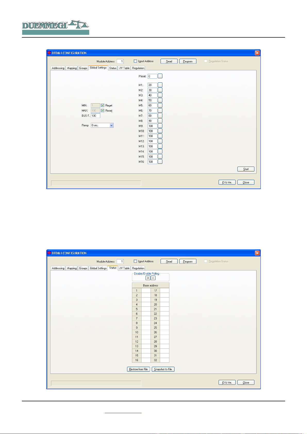
✗The code 139 saves, in the non volatile memor of the bal-
lasts, the brightness level which will be automaticall recalled
when a DALI or Domino bus failure occurs.
✗The change from a brightness level to another one will be ex-
ecuted according to a ramp that can be set as desired b the
codes 140 to 173. The ramp value will be stored in the non
volatile memor of the ballasts, therefore a power failure does
not affect it.
Management by DF P or by I/V table
The sending of commands or values to DALI devices can
be performed through a supervisor simpl writing the
memor locations of DFCP related to the output of the in-
stalled DFDALI modules.
As option, or in addition, it is possible to send commands or
value from DFCP to the DALI module through proper equa-
tions as in the following example:
V1 = !(I1.1 | I1.2 | I1.3)
AO2 = P(128)V1 & \
P(125)I1.1 & P(126)I1.2 & \
P(50)I1.3
where I1.1 and I1.2 are, for instance, the Up and Down
inputs and AO2 is DFDALI module with address 2; I1.3
will set the brightness to 50%. The specified value, at each
variation, will be transferred to the DALI output (AO2). At
the releasing of each pushbutton, the value is alwa s set to
128 (no operation, but needed to inform the module about
the releasing of the buttons). In this case the described Up,
Down and Preset functions acts on all connected ballasts
(broadcast commands).
To get the same result on a ballast individuall addressed,
it is easiest (even if not mandator ) to use the hexadecimal
format to write the equations, because the address of the
ballast has to be specified in the high b te of the channel:
V1 = !(I1.1 | I1.2 | I1.3)
AO2 = P(0x0180)V1 & \
P(0x017D)I1.1 & P(0x017E)I1.2 & \
P(0x0132)I1.3
where I1.1 and I1.2 are the Up and Down inputs and
AO2 is DFDALI with address 2; I1.3 will set the brightness
to 50%. The specified value, at each variation, will be trans-
ferred to the DALI ballast addressed 1. At the releasing of
each pushbutton, the value is alwa s set to 0x0180 (no
operation, but needed to inform the module about the re-
leasing of the buttons).
A similar example follows to send command to a group of
ballasts:
V1 = !(I1.1 | I1.2 | I1.3)
AO2 = P(0x8180)V1 & \
P(0x817D)I1.1 & P(0x817E)I1.2 & \
P(0x8132)I1.3
The specified value, at each variation, will be transferred to
the DALI devices assigned to group 1. At the releasing of
each pushbutton, the value is alwa s set to 0x8180 (no
operation, but needed to inform the module about the re-
leasing of the buttons).
Of course the commands to DALI devices can be also sent
b DFCP through the using of the Scripts.
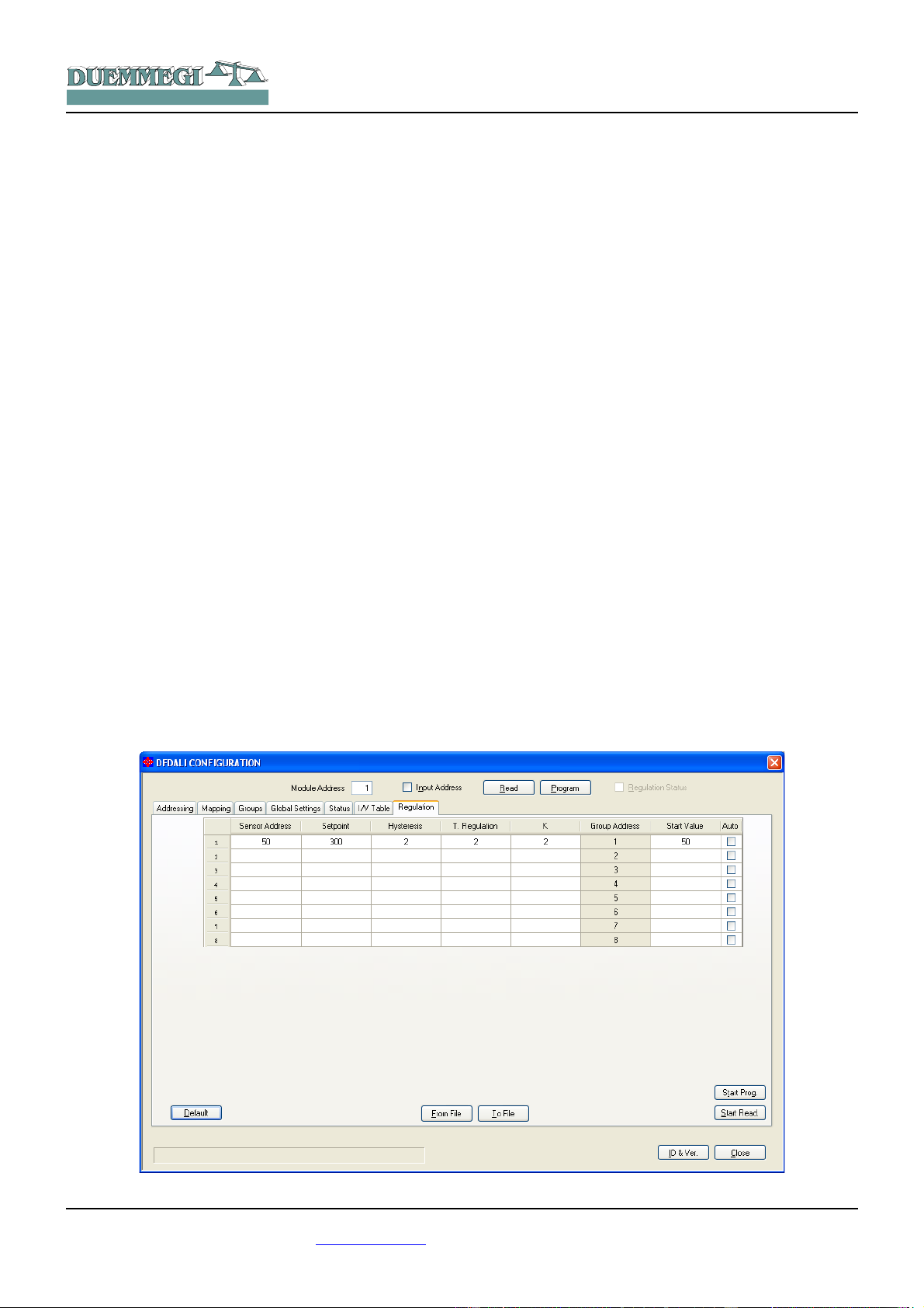
DFDALI module can however work without DFCP control-
ler, simpl linking the desired commands to bus input
points (both real and virtual ones); for details about this
possibilit , refer to the paragraph I/V Table.
Manual commands by the module
pushbutton
Near to the terminal block of DALI line, a pushbutton allows
the following functions: a short pulse will cause the com-
plete switching ON and OFF, while holding down the button
the brightness increases or decreases depending on previ-
ous action (ever next continuous pressing will invert the
previous one).
This pushbutton is useful during the setting up of the plant.
Diagnostic of DALI line by yellow LED
The ellow LED, located near the just described pushbut-
ton, continuousl flashes during normal operation. Since
the DALI line is continuousl polled in a sequential wa ,
thus the LED flashes in the same wa , even if DFCP con-
troller is not connected.
The ellow LED will be fixed lighted when one or more of
the following events will occur on the DALI line:
•Lamp failure
•DALI line broken or no ballast connected
•Short circuit on DALI line
In the case of short circuit, an automatic procedure will tr
to restore the line, thus allowing to module to return to to
the normal operation with a maximum 15 sec dela after
the short circuit condition has been removed.
The LED will be instead switched off if the DALI section of
the module is not supplied or if the polling has been dis-
abled. In an case, the occurred problem can be discrimin-
ated b the map of DCP IDE or BDTools or b a supervisor
or video-terminal connected to DFCP (reading input chan-
nel as described in the related paragraph).
Note:
✗In lamp failure condition, it is not possible to know on which
DALI device this event occurred.
DUEMMEGI s.r.l. - Via Longhena, 4 - 20139 MILANO
Tel. 02/57300377 - Fax 02/55213686 – www.duemmegi.it
Rel.: 2.1 Ma 2013 Page 4 of 11
HOME AND BUILDING AUTOMATION

Domino
DFDALI
Mapping
DFDALI module is shown into the map of DCP IDE or
BDTools like in the following figure. As for all Domino mod-
ules, the background of the module will be in green color if
the module is connected and properl working, otherwise
the background will be in red color.
The portion on the left side is related to the input section
and it reports the diagnostic information and the brightness
level of ballast 1 (text box on the bottom); if the option
“Regulation status” has been checked in the configuration
panel, then this text box reports the automatic regulation
status of the 8 zones (in decimal format to be interpreted in
binar mode).
The portion on the right side is related to the output section
and it features two text boxes for entering the destination
and command values.
Setting up
DCP IDE and BDTools allow to set the operating paramet-
ers of the DALI line during the s stem setting up and to
perform some diagnostic functions. DFDALI module can be
adapted to an specific application. The setting up is per-
formed via the Domino bus and DFCP (or DFRS or
DFPRO) through a specific configuration panel that can be
accessed from the menu of DCP IDE or BDTools.
From the menu, select Programming, Modules Configura-
tion and then DFDALI. The window shown in Figure 2 will
be opened; the main parameters and options can be here
defined as it will be described in the following of this para-
graph.
Before to proceed with an action, the communication
between the PC and, for instance, DFCP has to be opened.
The top side of the configuration panel reports the section
for the addresses management.
After having entered the address of the DFDALI to be man-
aged, it is possible to enable the input address of the mod-
ule through the check box named “Input Address” and then
clicking on the button Program; b the button Read it is in-
stead possible to check the current setting.
It is also possible to activate the “Regulation Status” inform-
ation related to the 8 zones b checking the related option
and then pressing the button Program. This option, of
course, requires that the input section have been enabled.
Six tabs in the window allow some well defined functions as
described in the following.
The button ID & Ver. on the lower side allows to read the
firmware version of the selected DFDALI module.
DUEMMEGI s.r.l. - Via Longhena, 4 - 20139 MILANO
Tel. 02/57300377 - Fax 02/55213686 – www.duemmegi.it
Rel.: 2.1 Ma 2013 Page 5 of 11
HOME AND BUILDING AUTOMATION
Figure 2: Configuration panel – Addressing TAB

Domino
DFDALI
Addressing
3 mutuall exclusive functions are available:
Set address. In the first case, an address will be assigned
to all the connected ballasts, and the starting address can
be chosen (the t pical value is 1).
This t pe of addressing assigns consecutive values, in the
range 1 to 32, to the ballasts in a random order.
If some ballasts on the line have been previousl ad-
dressed and some other ballasts have to be added, the ad-
dressing procedure can be performed without an modifica-
tion to the previousl assigned addresses. Mainl in this
case, a starting address other than 1 can be useful. A timer
icon will inform that the operation is running.
At the end of the procedure, the normal mouse icon will be
restored. The time required for this procedure is about:
T = 5sec + (6sec x “nr. of ballasts”)
Remove the address. If some addressing or reconfiguration
errors occurred, it can be useful removing the address of all
the ballasts on the line or of a well specified ballast.
Restore the factory setting. The DALI ballasts are factor
set without an address and with a basic configuration for
the main parameters; the following table shows a t pical
default configuration:
Parameter Value
Minimum brightness level 1%
Maximum brightness level 100%
Brightness level in failure condi-
tions
100%
Ramp value 0 seconds
Preset None
These settings can be restored both for all ballasts connec-
ted to the line and for a single ballast.
Restoring of the settings does not impl the reset of the
ballast address. The visible result of the factor setting
restoring is the switching on of the lamps at the bus failure
default level, that is t picall 100%.
Mapping
Once the ballasts have been random addressed, it can be
useful to reorder the assigned addresses, thus simplif ing
the supervision and the management of ballasts, Figure 3.
The address 1 to 32 of each ballast can be changed to a
new desired value (alwa s in the range 1 to 32). For each
address, the program shows a line similar to the following
one: .
The button 0 allows to switch off the ballast with address
specified in the gra text box (1 in this example) while the
button I allows the switching on; this function is useful to
see where the ballast addressed 1 (in this example) is
ph sicall located. In the white text box the new desired ad-
dress must be entered (23 in this example) for the ballast
whose current address is 1.
The execution of the mapping procedure (pressing the but-
ton Start) will take place onl for the ballasts selected b
the related checkbox. A timer icon will inform that the oper-
ation is running. At the end of the procedure, the normal
mouse icon will be restored. The time require b the map-
ping procedure is about 1sec per ballast.
If the procedure has not been successfull executed, a win-
dow reporting “Error during mapping” will appear.
DUEMMEGI s.r.l. - Via Longhena, 4 - 20139 MILANO
Tel. 02/57300377 - Fax 02/55213686 – www.duemmegi.it
Rel.: 2.1 Ma 2013 Page 6 of 11
HOME AND BUILDING AUTOMATION
Figure 3: Mapping

Domino
DFDALI
In this case, follows these steps:
•click on the button “Recover” to remove the address of
each ballast for which the mapping procedure has not
been successfull completed
•address again the ballasts without address selecting
as starting address a free value followed b a suffi-
cient number of free addresses (see the Status TAB)
•execute again the mapping procedure
The correctness of the changes made can be checked b
switching on and off the ballasts using the buttons identified
as 0 (off) and I (on).
The two big buttons 0 and I on the left side allow to switch
off and to switch on all the ballasts connected to the line.
The buttons Select (select all) and Deselect (deselect all)
and Reset (restore the address value in the consecutive or-
der) complete this TAB.
Groups
This TAB, Figure 4, features a grid where each ballast can
be assigned to one or more groups. This choice can be
done b clicking on each cell located at the intersection
between the desired ballast (the columns) and the desired
group (the rows).A X s mbol will be shown in the related
cell.
In the example of the figure
here on the right side, the
group 1 contains the ballasts
1-2-5, the group 2 the bal-
lasts 1-3 and the group 3 the
ballasts 2-4-5.
The button Deselect remove all the X s mbols on the grid.
The execution of the assignment of the groups (clicking on
the button Start) will take in account onl the ballast selec-
ted b the X s mbol. A timer icon will inform that the opera-
tion is running. At the end of the procedure, the normal
mouse icon will be restored.
If the procedure has not been successfull executed, the
warning in following window will be shown:
In this case the procedure has to be repeated.
The correctness of the changes made can be checked b
switching on and off the ballasts using the buttons identified
as 0 (off) and I (on); the buttons on the top side act on the
single ballast, the buttons on the left side act on the groups
and the two big buttons 0 and I switch off and on all the bal-
last on the line.
The buttons From File and To File allow to store and recall
the settings of the groups; take in account that it is not pos-
sible to read, from DFDALI module, the current settings of
the groups, therefore it is strongl recommended to save
them into a file for future modifications.
The time required b this procedure is about:
T = 8sec + (0,5sec x “nr. of X in the window”)
DUEMMEGI s.r.l. - Via Longhena, 4 - 20139 MILANO
Tel. 02/57300377 - Fax 02/55213686 – www.duemmegi.it
Rel.: 2.1 Ma 2013 Page 7 of 11
HOME AND BUILDING AUTOMATION
Figure 4: Groups

Domino
DFDALI
lobal Settings
In this TAB, Figure 5, it is possible to set, for all ballasts on
the DALI line, the following parameters:
MIN: minimum brightness value (%); enabling the Reset
check box, the default value will be restored (1%).
MAX: maximum brightness value (%); enabling the Reset
check box, the default value will be restored (100%).
BUS F.: the brightness value (%) to be recalled b ballasts
during failure of Domino and/or DALI bus.
Ramp: the ramp value in seconds.
Preset: writing a value (0 to 100) and clicking on the button
on the right side, the brightness will be forced to that value.
M1
÷
M16: the value to be loaded into the 16 presets; the
button on the right side allows to recall the related preset
stored into the ballast.
DUEMMEGI s.r.l. - Via Longhena, 4 - 20139 MILANO
Tel. 02/57300377 - Fax 02/55213686 – www.duemmegi.it
Rel.: 2.1 Ma 2013 Page 8 of 11
HOME AND BUILDING AUTOMATION
Figure 5: Global Setting
Figure 6: Status

Domino
DFDALI
Enter the desired parameters and then click on Start to
send the configuration. The time required b this procedure
is about 15 seconds.
If the procedure has not been successfull executed, a
warning window will be shown; in this case the procedure
has to be repeated.
Status
This TAB, Figure 6, shows, if the ballasts have been ad-
dressed, the current brightness level of each ballast. These
values are in the range 1 to 100; when a ballast does not
answer to the polling, the reported value will be 255 (and
the table will show “-”).
If a lamp failure occurs, a X s mbol on a pink background
will be shown.
In addition it is possible to force the brightness entering the
value in the cell related to the desired device and confirm-
ing b the Enter ke .
A pair of buttons on the top side of the table allow to enable
and disable the polling on the DALI line. When the polling is
disabled, the label “Base address” will be shown over a red
background.
The buttons “Snapshot to File” and “Restore from File” al-
low respectivel to save and recall a given configuration of
brightness levels; in this wa it is possible to save on the
PC one or more sceneries (each scener will be a file).
I/V Table
The TAB shown in Figure 7 allows to create up to 58 rela-
tionship between real or virtual inputs of the Domino bus
and the following commands: Up, Down, Single Command,
Save scener and Recall scener . For each command
simpl enter the input point (without I or V, with ! if negation
is required), the function and the channel or the scener .
These functions are managed directl b DFDALI module,
thus without the need of an controller and an program-
ming.
To compile the table, left click with the mouse on the first
available cell on the Input column, enter address and point
(without I or V, with ! if needed) and press
Enter. The command list will appear:
choose the desired function among Mono,
Up, Down, Recall, Save; the other two op-
tions are related to the automatic bright-
ness regulation, see next paragraph. The
cell of the column Cmd will then show the
s mbol of the chosen function; to change
the function, simpl click again on the cell.
Select the desired function; the cell of the column Cmd will
then show the s mbol of the chosen function (U, D, M, R,
S); to change the function, simpl click again on the cell.
The next cell on the column B/G (Broadcast or Group) will
be then automaticall highlighted: enter the desired value,
that is 0 for Broadcast or the desired group number number
1 to 15 (note: group 16 cannot be used in the I/V table) and
press Enter. If instead the desired function is Save or Re-
call scener , press Enter again: the related cell will be auto-
maticall highlighted in the column S (Scener ): enter the
desire number, that is the number of the scener (1 to 16)
to be saved or recalled, then press Enter.
The buttons Start Prog. and Start Read. in the I/V Table
TAB allow, respectivel , to transfer the values currentl
shown in the I/V Table to DFDALI module and read the cur-
rent configuration of DFDALI and report it into the table.
The buttons From File and To File allow, respectivel , to
open a file, with .TIV extension, containing a previousl
saved I/V table and to save the I/V table shown in the win-
dow to a file. The Default button clears the table.
DUEMMEGI s.r.l. - Via Longhena, 4 - 20139 MILANO
Tel. 02/57300377 - Fax 02/55213686 – www.duemmegi.it
Rel.: 2.1 Ma 2013 Page 9 of 11
HOME AND BUILDING AUTOMATION
Figure 7: I/V Table

Domino
DFDALI
Automatic brightness regulation
DFDALI module, starting from firmware version2.0, imple-
ments the automatic brightness regulation as function of a
light sensor connected to the Domino bus (e.g. DFLUX).
The TAB shown in Figure 8 allow to manage up to 8 zones
(each one corresponding to a group in the range 1 to 8).
These functions are managed directl b DFDALI module,
therefore no controller or specific programming is required.
To fill the table, double left click in the cell related to the
zone to be set in the Sensor Address column, enter the ad-
dress of the light sensor (e.g. DFLUX module) for that zone
and press Enter. The cell related to Setpoint will be then
automaticall highlighted: enter the desired value and press
Enter. The sequence is the same also for the next paramet-
ers: H steresis, T. Regulation, K and Start Value.
Setpoint is the brightness level that has to be kept. The
regulation function works in order to keep the light value
read from the sensor in the range (setpoint - h steresis) to
(setpoint + h steresis).
The regulation time, in seconds, is the interval with which
the module compares the light level read b the sensor to
the setpoint.
K is a parameter which, multiplied b the error (defined as
the difference between the setpoint and the brightness
value measured b the sensor), defines the magnitude of
the increase or the decrease, in respect to the previous
value, to be sent to the ballasts. In practice, larger values of
K increase the speed of the approaching to the set point.
Small values of K allow for greater stabilit of the regulation
but a slower response, while large values of K make the re-
sponse faster, but some oscillations can appear.
Start Value is the value from which the regulation starts
when it is activated.
The Auto options, when checked, place that zone in auto-
matic regulation mode at the power up of the ballasts or of
the Domino bus; if the option is not checked, the lights will
go to the value set in the ballasts (t picall 100 %).
Figure 8 shows some t pical value for the just described
parameters.
The buttons Start Prog. and Start Read. allow, respectivel ,
to transfer the values currentl shown in the table to DF-
DALI module and read the current configuration of DFDALI
and report it into the table.
The buttons From File and To File allow, respectivel , to
open a file, with .TRG extension, containing a previousl
saved regulation table and to save the table shown in the
window to a file. The Default button clears the table.
To change the setpoint value of a group from a supervisor
or similar devices, the destinations 0x91 ÷ 0x98 have to be
used, as described in “Commands via bus” paragraph.
The functions 0xDD, 0xDE 0xDF allow to enable and dis-
able the automatic regulation from the bus on the group
specified b the Destination field (0x81 ÷ 0x88)
DUEMMEGI s.r.l. - Via Longhena, 4 - 20139 MILANO
Tel. 02/57300377 - Fax 02/55213686 – www.duemmegi.it
Rel.: 2.1 Ma 2013 Page 10 of 11
HOME AND BUILDING AUTOMATION
Figure 8: Automatic brightness regulation

Domino
DFDALI
Technical characteristics
Suppl voltage Domino bus
side
B specific centralized power
suppl mod. DFPW2
Suppl voltage DALI bus
side
12V~ (at full load) 3VA MIN, or
12V ±5% 0.25A MIN
Current consumption on
Domino bus side
Equal to 2 standard Domino
modules
MAX current consumption
DALI bus side
0.25A at 12V , 3VA at 12V~
Number of managed DALI
devices
32 MAX
Number of generic
commands
58 (I/V Table)
Operating temperature -5 ÷ +50 °C
Storage temperature -20 ÷ +70 °C
Protection degree IP20
Outline dimensions
90cm
58mm
71mm
DUEMMEGI
MILANO-ITALY ADDRESS
DFDALI
+
Domino
PATENTED
DA+
OUT
DALI
SUPPLY
+_
BUS
DA-
IN
orrect disposal of this product
(Waste Electrical & Electronic Equipment)
(Applicable in the European Union and other
European countries with separate collection s s-
tems). This marking on the product, accessories or
literature indicates that the product should not be
disposed of with other household waste at the end
of their working life. To prevent possible harm to
the environment or human health from uncontrolled waste dispos-
al, please separate these items from other t pes of waste and re-
c cle them responsibl to promote the sustainable reuse of materi-
al resources. Household users should contact either the retailer
where the purchased this product, or their local government of-
fice, for details of where and how the can take these items for en-
vironmentall safe rec cling. This product and its electronic ac-
cessories should not be mixed with other commercial wastes for
disposal.
Installation and use restrictions
Standards and regulations
The design and the setting up of electrical s stems must be per-
formed according to the relevant standards, guidelines, specifica-
tions and regulations of the relevant countr . The installation, con-
figuration and programming of the devices must be carried out b
trained personnel.
The installation and the wiring of the bus line and the related
devices must be performed according to the recommendations of
the manufacturers (reported on the specific data sheet of the
product) and according to the applicable standards.
All the relevant safet regulations, e.g. accident prevention regula-
tions, law on technical work equipment, must also be observed.
Safety instructions
Protect the unit against moisture, dirt and an kind of damage dur-
ing transport, storage and operation. Do not operate the unit out-
side the specified technical data.
Never open the housing. If not otherwise specified, install in closed
housing (e.g. distribution cabinet). Earth the unit at the terminals
provided, if existing, for this purpose. Do not obstruct cooling of the
units. Keep out of the reach of children.
Setting up
The ph sical address assignment and the setting of parameters (if
an ) must be performed b the specific softwares provided togeth-
er the device or b the specific programmer. For the first installa-
tion of the device proceed according to the following guidelines:
•Check that an voltage suppl ing the plant has been removed
•Assign the address to module (if an )
•Install and wire the device according to the schematic dia-
grams on the specific data sheet of the product
•Onl then switch on the 230Vac suppl ing the bus power sup-
pl and the other related circuits
Applied standards
This device complies with the essential requirements of the follow-
ing directives:
2004/108/CE (EMC)
2006/95/CE (Low Voltage)
2002/95/CE (RoHS)
Note
Technical characteristics and this data sheet are subject to change
without notice.
DUEMMEGI s.r.l. - Via Longhena, 4 - 20139 MILANO
Tel. 02/57300377 - Fax 02/55213686 – www.duemmegi.it
Rel.: 2.1 Ma 2013 Page 11 of 11
HOME AND BUILDING AUTOMATION
Table of contents
Other Duemmegi Gateway manuals
Popular Gateway manuals by other brands

Samsung
Samsung WEC8500 Operation manual

ZyXEL Communications
ZyXEL Communications P-660H-T Series quick start guide

Linksys
Linksys AG241 user guide

Juniper
Juniper SRX650 quick start guide

ZyXEL Communications
ZyXEL Communications P-660HU-Tx Quick start quide

Delta Energy Systems
Delta Energy Systems SOLIVIA Gateway M1 G2 Operation and installation manual