IAC INDUSTRIES Smart Plant WX User manual

IAC | 5200 Metcalf Avenue, Overland Park, KS 66202 USA
iac-intl.com | USA & Canada: 800-334-7431| Main Office: 913-384-5511
Smart Plant™Remote Monitoring Systems
INSTALLATION GUIDE
WX Outdoor Gateway

1-1
•Revision History
Release 1 –2022-11-15
IAC Form #: IAC-IG-001
In case of emergencycall 911.
For IAC afterhours troubleshootingandservice assistance contact:
IAC 24/7 CustomerSupportHotline
Phone:913-834-5511, Option# 4

1-2
TABLE OF CONTENTS
Contents
•Revision History ...................................................................................................................1-1
TABLE OF CONTENTS.......................................................................................................................1-2
1INTRODUCTION .......................................................................................................................1-3
1.1 PURPOSE..........................................................................................................................1-3
1.2 INTENDED AUDIENCE........................................................................................................1-3
1.3 HOW TO USE THIS GUIDE..................................................................................................1-3
2MOUNTING .............................................................................................................................2-4
2.1 PERFORMING INSTALLATION.............................................................................................2-4
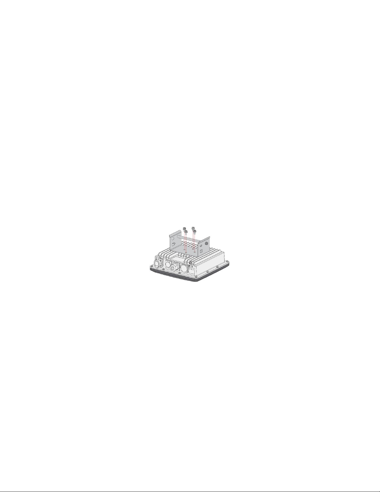
2.2 MOUNTING –STEP ONE (1)...............................................................................................2-4
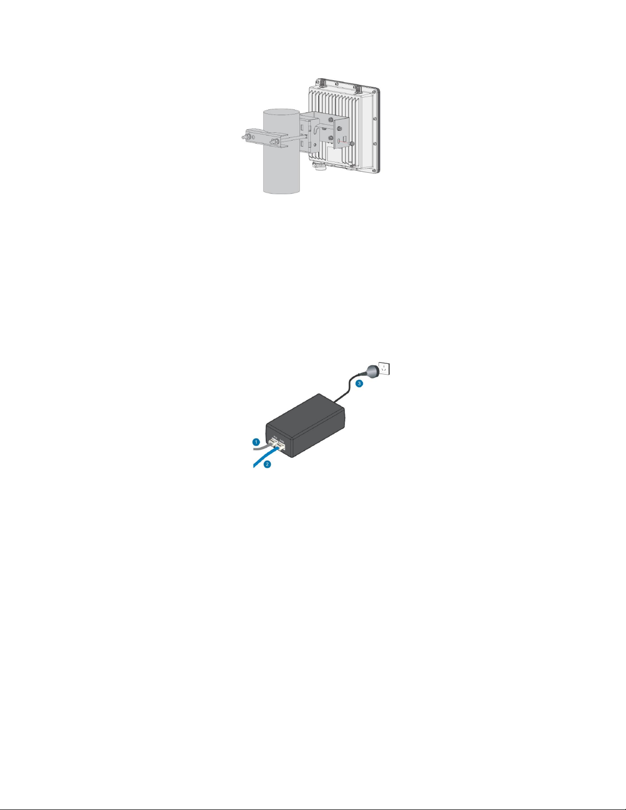
2.3 MOUNTING –STEP TWO (2) ..............................................................................................2-4
3CONNECT PoE ADAPTER.......................................................................................................2-5
4GROUNDING............................................................................................................................4-5
5LIGHTNING PROTECTION..........................................................................................................5-5
6ANTENNA................................................................................................................................6-6
7START UP.................................................................................................................................7-6
8OPERATION .............................................................................................................................8-6

1-3
1INTRODUCTION
1.1 PURPOSE
The WX outdoor gateway is a cellular backhaul device that communicates sensor readings
from local wireless WX sensor nodes and cloud based IoT platform.
1.2 INTENDED AUDIENCE
This guide will be useful for all users of the WX Outdoor Gateway. It will guide Operators and
Maintenance personnel through mounting, connection, start-up, and operation.
1.3 HOW TO USE THIS GUIDE
This guide will explain proper mounting, grounding, powering, and operation of the WX
gateway. It will also explain different LED status lights & troubleshooting device connection
issues.

2-4
2MOUNTING
2.1 PERFORMING INSTALLATION
Installation of this product should be performed by anappropriately licensed Electrician. The
device should be mounted away from sources of excessive heat or electrical interference and
be placed at a location central to all WX sensor nodes. Installation with line of sight to sensor
nodes is ideal, alsoinstallation at high elevation is preferred.
Installation and wiring methods should comply with all applicable Electrical codes.
2.2 MOUNTING –STEP ONE (1)
Fix the bracket included in the mounting kit on the bottom of the enclosure with four M6*12
screws.
2.3 MOUNTING –STEP TWO (2)
Position and tighten the pole clamps together around the pole with bolts, washers, and nuts.
The diameter of the pole that is supported by the brackets is 50-100 mm. If the pole diameter is
more than this value, hose clamps can be used. The standard mounting kit does not include
hose clamps. If needed, they should be purchased separately. The clamp's back also has
openings for hose clamps that are not included in the mounting kit. Position the enclosure and
fasten it with two M6*12 screws.

5-5
3CONNECT PoE ADAPTER
Connect the Ethernet cable from the enclosure to the Ethernet port labeled PoE adapter.
Connect one end of the power cord to the adapter. Connect the other end of the power cord to
a power outlet. Note that the PoE adapter is not rated for direct outdoor locations and must be
mounted within an appropriately rated weatherproof enclosure (not provided).
4GROUNDING
The gateway enclosure ground stud should be connected to a quality earth ground using at
minimum 10AWG wire.
5LIGHTNING PROTECTION
If the gateway is installed in a location with frequent lightning strikes and is located on a roof,
or other area that is a potential for a lightning strike it is recommended to install a lightning
arrestor between the antenna and the gateway. A device similar to L-Com AL6-NMNFBW-9 is
recommended. Consult factory for further details.

8-6
6ANTENNA
Attach all antennastothe Gateway(one LoRaantennafor8-channel gateways, two LoRaantennasfor
16-channel gateways).
7START UP
Applypowerto the PoE adapter. The PWRLED indicator onthe gatewayshouldlight up. During
bootupthe gatewaywill searchfor a cellular connectionandonce connected the LTE LED indicator will
beginto flash with data traffic. The LoRa1 LED indicator will light solid when the system is up and
running and ready to accept LoRa radio communicationfrom WX sensornodes
8OPERATION
The WX gatewayis provided fullyprovisionedandready for operation. There is no useradjustmentof
settings requiredfornormal operation. Monitoring of gateway operation is done by observingthe
statusLEDs on the gatewaybottom surface. During normal operationthe LEDs will show:
PWR –onsolid
LTE –blinking periodically
LoRa1 –on solid
If the LEDs do not indicate this statusthe gatewaymay be poweredOFF thenbackON. Note thatthe
gatewayhas a small amount of internal energy storage,so it is requiredtoremove powerforseveral
minutes forit to fully powerdown. Check the PWR led to ensure it is fullyOFF before re-applying
power.

8-7
WX Outdoor Gateway Installation Guide
Smart Plant Remote Monitoring Systems
Literature # IAC-IG-001
Release 1: 2022-11-15
IAC | 5200 Metcalf Avenue, Overland Park, KS 66202 USA
iac-intl.com | USA & Canada: 800-334-7431| Main Office: 913-384-5511
Table of contents