Duemmegi CONTATTO ModDALI User manual

Contatto
ModDALI
ModDALI: 4-channel DALI gateway
ModDALI module allows the management, through the
Contatto bus, of 4 DALI lines upon it's possible to connect
up to 32 devices for line or channel). In this way it's possi-
ble to control and regulate up to 128 DALI ballasts or other
similar devices). A firmware special ersion 6.x), available
on request, transforms the module into 2-lines for 64-
ballasts each one; the following refers to the standard
version unless otherwise specified.
ModDALI module performs, for each channel, the following
main features:
all timing functions are accomplished by the module
and it may be controlled by any real or virtual input of
the system, by supervisor or by video terminal
Up/Down and Single commands may be defined for
the manual regulation of lighting level
programmable ramp, in the range 0 to 60 seconds
setting of minimum and maximum output levels
dynamic lights scenes can be easily implemented
through MCP
the current brightness level may be stored and recalled
by the user; up to 16 presets are available to create
“real time” lighting scenes; the preset will be stored in
the non-volatile memory of the ballasts
if a Contatto bus failure or DALI bus failure occurs, the
output level will be automatically set to a user-defined
level
diagnostics of short circuit on the DALI lines and lamp
failure, with information about the line where the failure
occurred
galvanic insulation between DALI and Contatto buses
The 32 devices for each line can be controlled by:
Line: each command sent on a line will be executed by all
the devices connected on that same line, therefore all the
related devices will behave in the same way.
Individually: the commands will be individually sent to each
device, therefore each single device will behave indepen-
dently; for this operation, the DALI devices must be ad-
dressed as described in the following paragraphs.
Groups: the command will be sent to groups, therefore
each group of devices will behave independently; for this
operation, DALI devices must be addressed and the groups
must be defined as described in the following paragraphs.
The failure of a lamp or ballast can be detected and there-
fore reported only at line level and not individually. Mod-
DALI module can operate exclusively in systems with MCP
controller.
The ModDALI module provides a 5-way terminal blocks for
the connection to Contatto bus, a 2-way terminal block for
the supply voltage of DALI section and a 9-way terminal
blocks for the connection to the 4 DALI lines; all terminal
blocks are of removable type. A green LED on the front
panel reports the power-on condition.
On the front panel, four yellow LEDs report the communica-
tion status on the related DALI line; moreover these LEDs
report information about lamp failure and/or lines failure.
Four pushbuttons on the front panel, one for each DALI
line, allow the manual control of connected devices; the
possible functions, through these pushbuttons, are the con-
tinuous regulation of the brightness level and the one-touch
switching on and off.
ModDALI module is housed inside a standard DIN 6M
module for rail mounting.
Address programming
ModDALI module takes 1 output address and, if enabled, 1
input address with the same value both one made by 4
channels 16-bit).
The address has to be assigned by FXPRO programmer. A
white label on the front panel allows to write the pro-
grammed module address; a check box near to this label
allows to annotate if input address has been enabled or
not.
Operation
ModDALI features 1 output address with 4 channels 16 bit;
each channel is related to one of the 4 DALI lines. Sending
to the output address a code among the available ones
see following paragraphs), it's possible to perform the de-
sired function.
The easiest way to control each line connected to the DALI
ballasts is by two pushbuttons Up/Down) or by a single
pushbutton single command); these pushbuttons can be
connected to any Contatto input module and the operation
is like here bottom described.
Up/Down pushbuttons: pushing and holding the Up Down)
button, the brightness increases decreases) until the max
min) value is reached. When the brightness has reached
the desired level, release the button to hold it.
Single Command: holding down the button, the brightness
increases until the max value is reached. Releasing and
pushing again the button the brightness decreases to mini-
mum level. Release the button at desired level to hold it.
In addition to these simple manual commands, DALI de-
vices may be controlled by supervisor or by video terminal
ex. touch screen), simply writing on the output channel the
code of the function which must be executed and to which
ballast must be sent.
DUEMMEGI s.r.l. - Via Longhena, 4 - 20139 MILANO
Tel. 02/57300377 - Fax 02/55213686 – www.duemmegi.it
Rel.: 2.4 October 2017 Page 1 of 9

Contatto
ModDALI
Installation hints
The schematic diagram in Figure 1 shows the connections
to be made between ModDALI module, the Contatto bus,
the auxiliary power supply and the 4 DALI lines.
As said above, ModDALI module performs galvanic insula-
tion between DALI section and Contatto bus, through photo
couplers inside the module, while the 4 DALI lines are not
isolated each one to the others. All terminal identified as
DA- in the schematic are internally connected each one to
the others.
The auxiliary power supply AUX SUPPLY in the schematic
of Figure 1) can be a transformer with 12V~ secondary
winding at full load) 10VA, or it can be a stabilized dc pow-
er supply having output voltage in the range 15V to 24V
MAX), capable to deliver 1A; in this last case the polarity is
automatic, so the positive pole can be connected indiffer-
ently to the terminal 19 or 20. Warning: voltage over 24V
could damage the connected DALI devices.
It is suggested the using, for the DALI lines, of a normal 2-
core cables with double insulation. It's allowed to lay these
cables in the same pipe in which there are power cables,
provided that they have double isolation too.
It is recommended to avoid the using of multi core cables
carrying both the two DALI signals and ballast supply, be-
cause the capacitive coupling between the signal wires and
the power lines may cause very dangerous conditions for
the human safety.
The following table gives some rules for the MINIMUM ca-
ble section. As said above, no special cables are required
for the 4 DALI lines, provided that they have double insula-
tion.
In any case, the distance between ModDALI module and
the farthest ballast must not be more than 300 meters.
Connection Suggested cable
Contatto bus 4 x 2.5 mmq unshielded
DALI SUPPLY 1 mmq if the power supply is near
to the module)
DALI lines
Up to: 2 x 0.50mmq
Up to 175m: 2 x 0.75mmq
Up to 230m: 2 x 1.00mmq
Up to 300m: 2 x 1.50mmq
During the setting up of the system, 4 pushbuttons on the
front panel allow the manual control of the connected bal-
lasts, separately for each line, even if MCP is disconnected
see the related paragraph).
On the front panel 4 LEDs are available for diagnostics
see the related paragraph).
In ormation rom and to ModDALI
Since ModDALI module features 4 identical channels both
input and output), the following description will be referred
to one channel only. A DALI line is related each channel of
the module.
Input section
On the input address, if enabled, 4 channels 16 bit are
available for diagnostics of DALI system, as described in
the following table:
DUEMMEGI s.r.l. - Via Longhena, 4 - 20139 MILANO
Tel. 02/57300377 - Fax 02/55213686 – www.duemmegi.it
Rel.: 2.4 October 2017 Page 2 of 9
Figure : Wiring connections for standard version (4-line / 32-ballast)
Power supply 24V=
25% / 45mA
+24V
0V
L1
L2
P
114 16 1715
Contatto
DUEMMEGI
MILANO-ITALY
2345678
13 19 20
ON
DA+
DA-
DA+
DA-
DA+
DA-
DA+
DA-
ADDRESS
MODDALI
DALI
SUPPLY
OUT IN
DALI Gateway
+24V
BUS
0V
L1
L2
AUX
SUPPLY
12V~
15÷24V=
DALI
1
DALI
32
DALI
1
DALI
32
9
A B C D

Contatto
ModDALI
Point Description
1
Current brightness
2
3
4
5
6
7
8
9-
10 -
11 Polling disabled
12 Power supply loss on DALI side
13 Test button pressed
14 Lamp failure
15 DALI line broken
16 DALI line short circuit
The first available information the 8 lower bits of the chan-
nel) is the brightness level of the ballast having address 1
on each DALI line assumed as reference for all the other
ballasts). Thus, to use this function, the ballasts have to be
addressed starting from address 1. The value of the current
brightness level is in the range 0 to 100; if no ballast has
been addressed as 1, then the reported value will be 255.
A lamp failure condition will be instead reported by the val-
ue 128; if the answer from the ballast will not be under-
stood the value 129 will be reported.
If the brightness level of each ballast on each DALI line is
required by the application, a script for MCP is available for
this purpose; contact DUEMMEGI for more information.
Output section
4 channels 16 bit are available on the output address for
the execution of commands to the ballasts, as described in
the following table:
Point Description
1
Function
2
3
4
5
6
7
8
9
Destination
10
11
12
13
14
15
16
DUEMMEGI s.r.l. - Via Longhena, 4 - 20139 MILANO
Tel. 02/57300377 - Fax 02/55213686 – www.duemmegi.it
Rel.: 2.4 October 2017 Page 3 of 9
Figure 2: Wiring connections for special version (2-line / 64-ballast)
Power supply 24V=
25% / 45mA
+24V
0V
L1
L2
P
114 16 1715
Contatto
DUEMMEGI
MILANO-ITALY
2345678
13 19 20
ON
DA+
DA-
DA+
DA-
DA+
DA-
DA+
DA-
ADDRESS
MODDALI
DALI
SUPPLY
OUT IN
DALI Gateway
+24V
BUS
0V
L1
L2
AUX
SUPPLY
12V~
15÷24V=
DALI
1
DALI
64
DALI
1
DALI
64
9
A B C D

Contatto
ModDALI
The destination can assume different values depending on
the typology of the addressed target, identified by the value
of the high byte of the channel, as in the following table:
Written data Destination
HEX DEC
0x00 0 All the ballasts on the line
0x01 ¸ 0x20 1 ¸ 32 single ballast 1¸32)
0x81 ¸ 0x90 129 ¸ 144 single group 1¸16) of ballasts
The function executed by the module depends on the value
written on the low byte of the channel, as described in the
following table:
Written data Function
HEX DEC
0x00 ¸ 0x64 0 ¸ 100 Set the brightness to 0¸100%
according to the current ramp
0x70 112 Disable polling
0x71 113 Enable polling
0x7D 125 Up command without one-touch
function
0x7E 126 Down command without one-
touch function
0x7F 127 Single command without one-
touch function
0x80 128
No operation (in this case the
value of the destination must be
zero)
0x87 135 Set the current brightness a
MIN value
0x88 136 Set the current brightness a
MAX value
0x89 137 Reset MIN value to default 1%)
0x8A 138 Reset MAX value to default
100%)
0x8B 139
Save the current brightness as
level to be loaded during bus
failure condition
0x8C ¸ 0xAA 140 ¸ 170 Set the current ramp to 0 ¸ 30
seconds 1s step)
0xAB ¸ 0xAD 171 ¸ 173 Set the current ramp to 40 ¸ 60
seconds step 10 s)
0xB5 ¸ 0xC4 181 ¸ 196 Save the current brightness to
Preset 1¸16
0xC9 ¸ 0xD8 201 ¸ 216 Recall brightness from Preset
1¸16 according to current ramp
Note:
the previous table applies to ModDALI module equipped with
firmware 2.0 or higher.
The value to be written in the channel to perform a given
function to a given destination will be thus:
in hexadecimal: 0xYYZZ where YY is the destination in
hexadecimal format HEX) and ZZ is the code of the
function in hexadecimal format HEX)
in decimal: K where K is given by [ 256 x YY) + ZZ],
where YY is the destination in decimal format DEC)
and ZZ is the code of the function in decimal format
DEC)
Notes:
ModDALI module, normally, polls all the ballasts connected to
the 4 lines; this polling can be disabled , independently for
each line, sending the code 112 of course losing all informa-
tion about the diagnostic and the current level). The code 113
enable again the polling; the current status of the polling is re-
ported bu the point 11 of the input channel if enabled). At the
module power up or after a reset the polling is always en-
abled by default.
The code 128 is required only to inform ModDALI about when
interrupt a running function. For instance, to perform an Up
function, the code 125 must be sent: the brightness will in-
crease until the sending of code 128.
The code 139 saves, in the non volatile memory of the bal-
lasts, the brightness level which will be automatically recalled
when during a DALI bus failure condition or during a commu-
nication loss with MCP controller.
The change from a brightness level to another one will be ex-
ecuted according to a ramp that can be set as desired by the
codes 140 to 173. The ramp value will be stored in the non
volatile memory of the ballasts, therefore a power failure does
not affect it .
The sending of commands or values to DALI devices can
be performed through a supervisor simply writing the mem-
ory locations of MCP related to the output channels of the
installed ModDALI modules.
As option, or in addition, it is possible to send commands or
value from MCP to the DALI channel through proper equa-
tions as in the following example:
V1 = !(I1.1 | I1.2 | I1.3)
AO2:1 = P(128)V1 & \
P(125)I1.1 & P(126)I1.2 & \
P( 50)I1.3
where I1.1 and I1.2 are, for instance, the Up and Down
inputs and AO2:1 is the channel 1 of the ModDALI module
with address 2; I1.3 will set the brightness to 50%. The
specified value, at each variation, will be transferred to the
DALI output AO2:1). At the releasing of each pushbutton,
the value is always set to 128 no operation, but needed to
inform the module about the releasing of the buttons).
To get the same result on a ballast individually addressed,
it is easiest even if not mandatory) to use the hexadecimal
format to write the equations, because the address of the
ballast has to be specified in the high byte of the channel:
V1 = !(I1.1 | I1.2 | I1.3)
AO2:1 = P(0x0080)V1 & \
P(0x017D)I1.1 & P(0x017E)I1.2 & \
P(0x0132)I1.3
where I1.1 and I1.2 are the Up and Down inputs and
AO2:1 is the channel 1 of the ModDALI module with ad-
dress 2; I1.3 will set the brightness to 50%.
DUEMMEGI s.r.l. - Via Longhena, 4 - 20139 MILANO
Tel. 02/57300377 - Fax 02/55213686 – www.duemmegi.it
Rel.: 2.4 October 2017 Page 4 of 9

Contatto
ModDALI
The specified value, at each variation, will be transferred to
the DALI output AO2:1). At the releasing of each pushbut-
ton, the value is always set to 0x0080 no operation, but
needed to inform the module about the releasing of the
buttons).
A similar example is true to send command to a group of
ballasts:
V1 = !(I1.1 | I1.2 | I1.3)
AO2:1 = P(0x0080)V1 & \
P(0x817D)I1.1 & P(0x817E)I1.2 & \
P(0x8132)I1.3
The specified value, at each variation, will be transferred to
the DALI devices assigned to group 1 on the channel
AO2:1). At the releasing of each pushbutton, the value is
always set to 0x0080 no operation, but needed to inform
the module about the releasing of the buttons).
Of course the commands to DALI devices can be also sent
by MCP through the using of the Scripts.
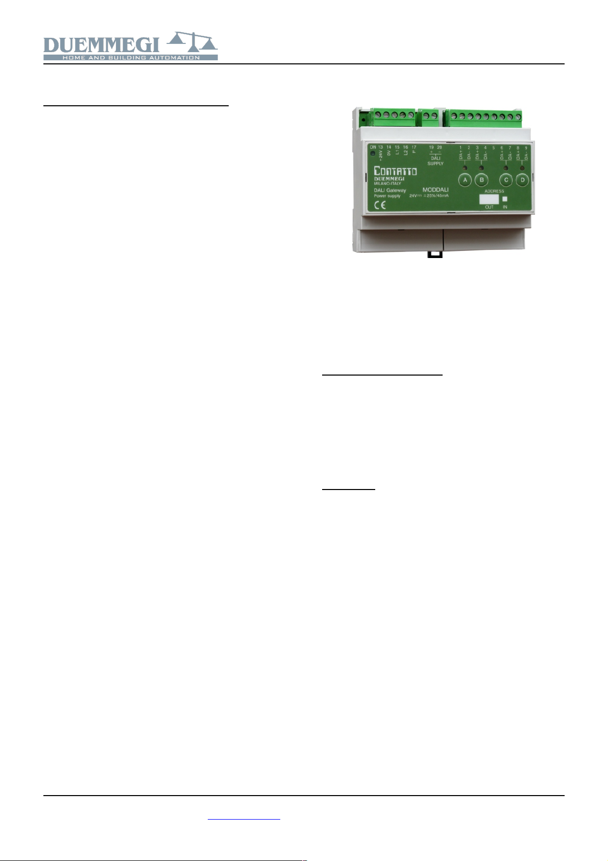
Commands rom the ront panel
Four pushbuttons on the front panel, related to each DALI
line, allow the following functions: a short pulse will cause
the complete switching ON and OFF, while holding down
the button the brightness increases or decreases depend-
ing on previous action every next continuous pressing will
invert the previous one). These pushbuttons are useful dur-
ing the installation procedure.
Meaning o the LEDs on the ront panel
For each DALI line, the related LED continuously flashes
during normal operation. Since the four lines are sequen-
tially polled, thus the LEDs flash in the same way, even if
MCP controller is not connected.
The LEDs on the front panel will be fixed lighted when
these one or more of the following events will occur on the
related DALI line:
•Lamp failure
•Dali line broken or no ballast connected
•Short circuit on DALI line
In the case of short circuit, an automatic procedure will try
to restore the fault line, thus allowing to module to return to
to the normal operation with a maximum 15 sec delay after
the short circuit condition has been removed.
All the LEDs will be instead switched off if the DALI section
of the module is not supplied terminals 19-20) or if the
polling has been disabled.
In any case, the occurred problem can be discriminated by
MCP Visio or by a supervisor or video-terminal connected
to MCP reading input channel as described in the related
paragraph).
Note:
In lamp failure condition, it is not possible to know on which
DALI device this event occurred: it is only possible to know on
which of the 4 lines of ModDALI the failure is present.
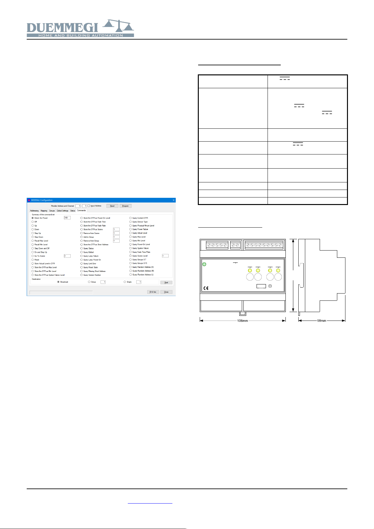
Setting the operating parameters
MCP IDE allows to set the operating parameters of each
DALI channel and to perform some diagnostic functions.
The setting up is performed via the Contatto bus and MCP
through a specific configuration panel which can be opened
selecting, from the menu of MCP IDE, “Configuration”,
“Lighting Gateway” and then “MODDALI”. The window in
Figure 3 will be shown. The following refers to the standard
version, but the procedures for the special version are
similar.
This configuration panel allows to set the main parameters
and some other options as described in the following of this
paragraph. Before to proceed with any other action, the
communication with MCP has to be enabled.
The top side of the DALITools window reports the section
for the addresses management. After having entered the
address of the ModDALI to be managed, it is possible to
enable the input address of the module through the check
box named “Input Address” and then clicking on the button
Program; by the button Read it is instead possible to check
the current setting, after having specified the desired mod-
ule address and the channel.
Six tabs in the window allow some well defined functions as
described in the following.
The button ID & Ver. on the lower side allows to read the
firmware version of the selected ModDALI module.
Addressing
3 mutually exclusive functions are available::
Set the address. In the first case, an address will be as-
signed to all the connected ballasts, and the starting ad-
dress can be chosen the typical value is 1). This type of
addressing assigns consecutive values, in the range 1 to
32, to the ballasts in a random order.
If some ballasts on the selected channel have been previ-
ously addressed and some other ballasts have to be
added, the addressing procedure can be performed without
any modification to the previously assigned addresses. A
timer icon will inform that the operation is running.
At the end of the procedure, the normal mouse icon will be
restored.
The time required for this procedure is about:
T = 5sec + 5sec x “nr. of ballasts”)
Remove the address. If some addressing or reconfiguration
errors occurred, it can be useful removing the address of all
the ballasts on the line or of a well specified ballast.
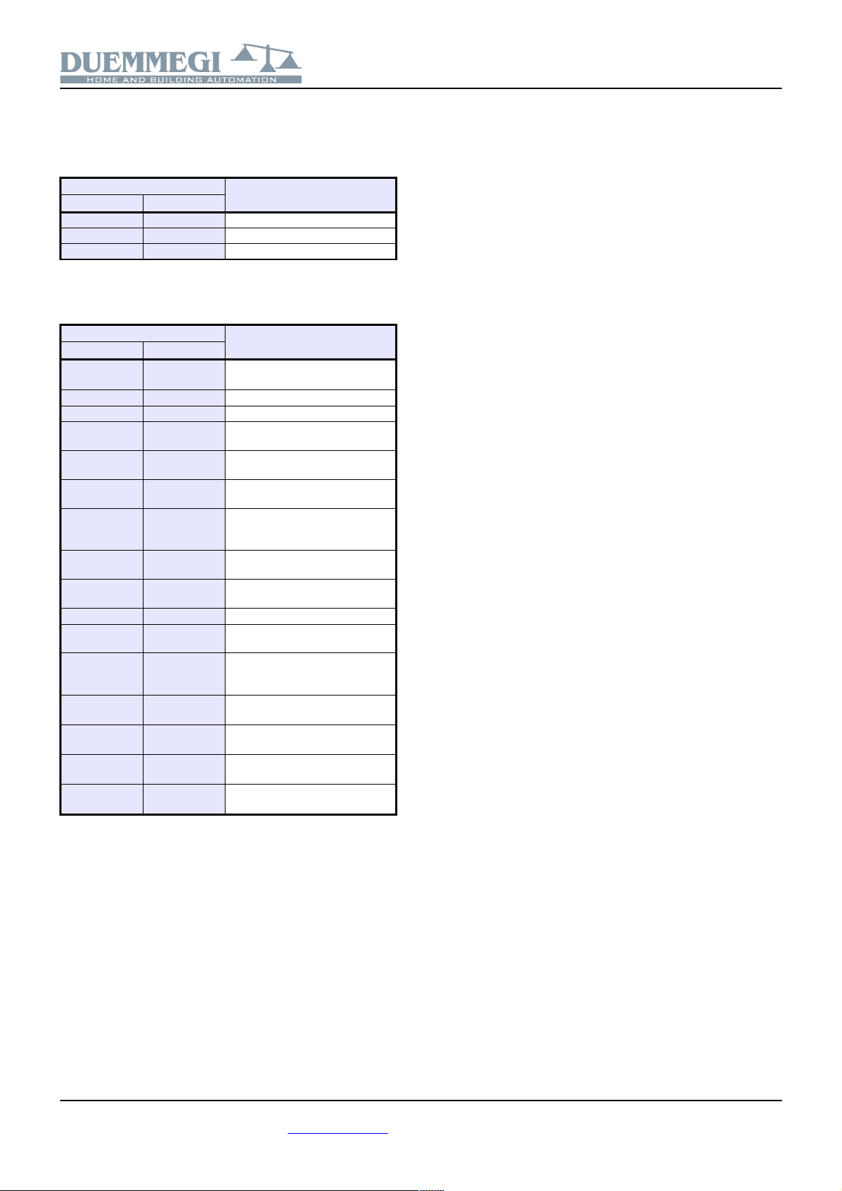
Restore the factory setting. The DALI ballasts are factory
set without any address and with a basic configuration for
the main parameters; the following table shows a typical
default configuration:
Parameter Value
Minimum brightness level 1%
Maximum brightness level 100%
Brightness level in failure condi-
tions
100%
Ramp value 0 seconds
Preset None
DUEMMEGI s.r.l. - Via Longhena, 4 - 20139 MILANO
Tel. 02/57300377 - Fax 02/55213686 – www.duemmegi.it
Rel.: 2.4 October 2017 Page 5 of 9

Contatto
ModDALI
These settings can be restored both for all ballasts con-
nected to that line and for a single ballast. Restoring of the
settings does not imply the reset of the ballast address.
The visible result of the factory setting restoring is the
switching on of the lamps at the bus failure default level,
typically at 100%.
Mapping
Once the ballasts have been random addressed, it can be
useful to reorder the assigned addresses in order to simpli-
fy the supervision and the management of the installed bal-
lasts.
Each ballast can be managed in order to change it previ-
ously assigned address to a new desired value always in
the range 1 to 32).
For each address, the program shows a line similar to the
following one: .
The button 0 allows to switch off the ballast with the ad-
dress specified in the gray text box 1 in this example)
while the button I allows the switching on; this function is
useful to see where the ballast addressed as 1 in this ex-
ample) is physically located. In the white text box the new
desired address must be entered 23 in this example) for
the ballast whose current address is 1.
The execution of the mapping procedure pressing the but-
ton Start) will take place only for the ballasts selected by
the related checkbox. A timer icon will inform that the oper-
ation is running. At the end of the procedure, the normal
mouse icon will be restored. The time require by the map-
ping procedure is about 1sec per ballast.
If the procedure has not been successfully executed, a
warning message will be shown; in this case follows these
steps:
•click on the button “Recover” to remove the address of
each ballast for which the mapping procedure has not
been successfully completed
•address again the ballasts without address selecting
as starting address a free value followed by a suffi-
cient number of free addresses see the Status TAB)
•execute again the mapping procedure
The correctness of the changes made can be checked by
switching on and off the ballasts using the buttons identified
as 0 off) and I on).
The two big buttons 0 and I on the left side allow to switch
off and to switch on all the ballasts connected to that line.
The buttons Select select all) and Deselect deselect all)
and Reset restore the address value in the consecutive or-
der) complete this tab.
DUEMMEGI s.r.l. - Via Longhena, 4 - 20139 MILANO
Tel. 02/57300377 - Fax 02/55213686 – www.duemmegi.it
Rel.: 2.4 October 2017 Page 6 of 9
Figure 3: Configuration Panel

Contatto
ModDALI
Groups
This tab features a grid where each ballast, on the selected
line, can be assigned to one or more groups. This choice
can be done by clicking on each cell located at the inter-
section between the desired ballast the columns) and the
desired group the rows). A X
symbol will be shown in the
related cell.
In the example of the figure
on this side, the group 1 con-
tains the ballasts 1-2-5, the
group 2 the ballasts 1-3 and
the group 3 the ballasts 2-4-5.
The button Deselect remove all the X symbols on the grid.
The execution of the assignment of the groups clicking on
the button Start) will take in account only the ballast dese-
lected by the X symbol. A timer icon will inform that the op-
eration is running. At the end of the procedure, the normal
mouse icon will be restored.
The time required by this procedure is about:
T = 8sec + 0,5sec x “nr. of X in the window”)
If the procedure has not been successfully executed, a
warning message will be shown; in this case the procedure
has to be repeated.
The correctness of the changes made can be checked by
switching on and off the ballasts using the buttons identified
as 0 off) and I on); the buttons on the top side act on the
single ballast, the buttons on the left side act on the groups
and the two big buttons 0 and I switch off and on all the bal-
last on that line.
The buttons From File and To File allow to store and recall
the settings of the groups; take in account that it is not pos-
sible to read, from ModDALI module, the current settings of
the groups, therefore it is strongly recommended to save
them into a file for future modifications.
Global Settings
In this tab it is possible to set, for all ballasts on the select-
ed line, the following parameters:
MIN: minimum brightness value 0-100%); enabling the Re-
set check box, the default value will be restored 1%).
MAX: maximum brightness value 0-100%); enabling the
Reset check box, the default value will be restored 100%).
BUS F.: the brightness value 0-100%) to be recalled by
ballasts during bus failure conditions on Contatto and/or
DALI bus; the value 101 means that the outputs will keep
the last value .
Ramp: the ramp value in seconds.
Pwr On: the brightness value 0-100%) to be recalled by
ballasts at their power up; the value 101 means that the
value outputted before the power off will be recalled.
Preset: writing a value 0 to 100) and clicking on the button
on the right side, the brightness will be forced to that value.
M
¸
M 6: the value to be loaded into the 16 presets; the
button on the right side allows to recall the related preset
stored into the ballast.
Enter in this tab the desired parameters and then click on
Start to send the configuration. A timer icon will inform that
the operation is running. The time required by this proce-
dure is about 15 seconds. If the procedure has not been
successfully executed, a warning message will be shown;
in this case the procedure has to be repeated.
Status
DUEMMEGI s.r.l. - Via Longhena, 4 - 20139 MILANO
Tel. 02/57300377 - Fax 02/55213686 – www.duemmegi.it
Rel.: 2.4 October 2017 Page 7 of 9

Contatto
ModDALI
This tab provides, if the ballasts have been addressed,
shows the current brightness level of each ballast on all the
4 channels. These values are in the range 1 to 100; when a
ballast does not answer to the polling, the reported value
will be 255 and the table will show “-”). If a lamp failure oc-
curs, a X symbol on a pink background will be shown.
In addition it is possible to force the brightness entering the
value in the cell related to the desired device.
4 pairs of buttons in the top side of the table allow to enable
and disable the polling independently for each channel of
the module. When the polling is disabled, the related label
of the channel will be shown over a red background.
The buttons “Snapshot to File” and “Restore from File” al-
low respectively to save and recall a given configuration of
brightness levels; in this way it is possible to save on the
PC one or more scenery each scenery will be a file).
Commands
This tab provides a several commands belonging to DALI
protocol; this section is addressed to highly qualified staff,
so it is recommended not to use it if you are not aware of
what you are doing.
Technical characteristics
Supply voltage Contatto bus
side
24V ± 25%
Supply voltage DALI bus
side
12V~ -5% ¸ +35% at full load)
or
15V ¸ 24V
Note: voltage over 24V
could damage the connected
DALI devices
MAX current consumption
Contatto bus side
45mA
MAX current consumption
DALI bus side
1A at 18V , 10VA a 12V~
Number of DALI lines Standard version: 4
Special version: 2
Number of DALI devices for
each line
Standard version: 32 MAX
Special version: 64 MAX
Operating temperature -10 ¸ +50 °C
Storage temperature -30 ¸ +85 °C
Protection degree IP20
Outline dimensions
DUEMMEGI s.r.l. - Via Longhena, 4 - 20139 MILANO
Tel. 02/57300377 - Fax 02/55213686 – www.duemmegi.it
Rel.: 2.4 October 2017 Page 8 of 9
90mm
Power supply 24V= 25% / 45mA
+24V
0V
L1
L2
P
114 16 1715
Contatto
DUEMMEGI
MILANO-ITALY
2 3 4 5 6 7 813 19 20ON
DA+
DA-
DA+
DA-
DA+
DA-
DA+
DA-
ADDRESS
MODDALI
DALI
SUPPLY
OUT IN
DALI Gateway
9
A B C D

Contatto
ModDALI
Correct disposal of the product (waste electrical & electronic
e uipment)
Applicable in the European Union and other European
countries with separate collection systems). This mark-
ing on the product, accessories or documentation indi-
cates that the product and its electronic accessories
should not be disposed of with other household waste
at the end of their working life. To prevent possible harm to the en-
vironment or human health from uncontrolled waste disposal,
please separate these items from other types of waste and recycle
them responsibly to promote the sustainable reuse of material re-
sources. Household users should contact either the retailer where
they purchased this product, or their local government office, for
details of where and how they can take these items for environ-
mentally safe recycling. Business users should contact their suppli-
er and check the terms and conditions of the purchase contract.
Adequate disposal of the decommissioned equipment for recy-
cling, treatment and environmentally compatible disposal contrib-
utes in preventing potentially negative effects on the environment
and health and promotes the reuse and/or recycling of equipment
materials. Abusive product disposal by the user is punishable by
law with administrative sanctions.
Installation and use restrictions
Standards and regulations
The design and the setting up of electrical systems must be per-
formed according to the relevant standards, guidelines, specifica-
tions and regulations of the relevant country. The installation,
configuration and programming of the devices must be carried out
by trained personnel.
The installation and the wiring of the Contatto bus line and the re-
lated devices must be performed according to the recommenda-
tions of the manufacturers reported on the specific data sheet of
the product) and according to the applicable standards.
All the relevant safety regulations, e.g. accident prevention regula-
tions, law on technical work equipment, must also be observed.
Safety instructions
Protect the unit against moisture, dirt and any kind of damage dur-
ing transport, storage and operation.
Do not operate the unit outside the specified technical data.
Never open the housing. If not otherwise specified, install in closed
housing e.g. distribution cabinet).
Earth the unit at the terminals provided, if existing, for this purpose.
Do not obstruct cooling of the units.
Setting up
The physical address must be assigned with the specific program-
mer and the setting of parameters if any) must be performed by
the specific configuration softwares; for more details refer to the
specific data sheet of the product. For the first installation of the
device, generally and unless otherwise specified on the specific
data sheet of the product, proceed according to the following
guidelines:
•Check that any voltage supplying the plant has been removed
•Assign the address to module if any)
•Install and wire the device according to the schematic diagrams
on the specific data sheet of the product
•Only then switch on the 230Vac supplying the bus power supply
and the other related circuits
Applied standards
The devices belonging to Contatto line comply with the essential
requirements of the following directives:
2014/30/UE EMC)
2014/35/UE Low Voltage)
2011/65/UE RoHS)
Note
Technical characteristics and this data sheet are subject to change
without notice.
DUEMMEGI s.r.l. - Via Longhena, 4 - 20139 MILANO
Tel. 02/57300377 - Fax 02/55213686 – www.duemmegi.it
Rel.: 2.4 October 2017 Page 9 of 9
Table of contents
Other Duemmegi Gateway manuals