SolarEdge SE1000 User manual

Disclaimers
Control and Communication Gateway Installation Guide - MAN-01-00132-1.2
1
Disclaimers
Important Notice
Copyright © SolarEdge Inc. All rights reserved.
No part of this document may be reproduced, stored in a retrieval system or transmitted, in any form or
by any means, electronic, mechanical, photographic, magnetic or otherwise, without the prior written
permission of SolarEdge Inc.
This document is solely for the use of SolarEdge customers and employees.
The material furnished in this document is believed to be accurate and reliable. However, SolarEdge
assumes no responsibility for the use of this material. SolarEdge reserves the right to make changes to the
material at any time and without notice. You may refer to the SolarEdge web site (www.solaredge.com)
for the most updated version.
All company and brand products and service names are trademarks or registered trademarks of their
respective holders.
Patent marking notice: http://www.solaredge.com/groups/patent
Exclusion of Liability
The general terms and conditions of delivery of SolarEdge shall apply.
The content of these documents is continually reviewed and amended, where necessary. However,
discrepancies cannot be excluded. No guarantee is made for the completeness of these documents.
FCC Compliance
This equipment has been tested and found to comply with the limits for a Class B digital device, pursuant
to part 15 of the FCC Rules. These limits are designed to provide reasonable protection against harmful
interference in a residential installation. This equipment generates, uses and can radiate radio frequency
energy and, if not installed and used in accordance with the instructions, may cause harmful interference
to radio communications. However, there is no guarantee that interference will not occur in a particular
installation. If this equipment does cause harmful interference to radio or television reception, which can
be determined by turning the equipment OFF and ON, you are encouraged to try to correct the
interference by one or more of the following measures:
Reorient or relocate the receiving antenna.
Increase the separation between the equipment and the receiver.
Connect the equipment into an outlet on a circuit different from that to which the receiver is
connected.
Consult the dealer or an experienced radio/TV technician for help.
Changes or modifications not expressly approved by the party responsible for compliance may void the
user’s authority to operate the equipment.

Table of Contents
Control and Communication Gateway Installation Guide - MAN-01-00132-1.2
2
Table of Contents
Disclaimers......................................................................................................................... 1
Important Notice ...............................................................................................................1
Exclusion of Liability...........................................................................................................1
FCC Compliance .................................................................................................................1
Table of Contents ............................................................................................................... 2
About This Guide................................................................................................................ 4
Support and Contact Information....................................................................................... 5
Handling and Safety Instructions ........................................................................................ 6
Chapter 1: Introducing the SolarEdge Control and Communication Gateway ...................... 7
Overview............................................................................................................................7
Control and Communication Gateway Interfaces..............................................................8
LCD and LCD-Menu Buttons...............................................................................................9
LEDs ...................................................................................................................................9
Communication Connectors ..............................................................................................9
Other Interfaces...............................................................................................................10
Chapter 2: Installing the SolarEdge Gateway .................................................................... 11
Safety...............................................................................................................................11
Transport and Storage .....................................................................................................11
Package Contents ............................................................................................................11
Installation Equipment.....................................................................................................11
Installation Guidelines .....................................................................................................12
Installation Workflow ......................................................................................................12
Mounting and Connecting the SolarEdge Gateway .........................................................13
Connecting the SolarEdge Gateway to AC .......................................................................14
Chapter 3: Connecting the SolarEdge Gateway to the SolarEdge Installation .................... 15
Overview..........................................................................................................................15
Connecting and Configuring the RS485 ...........................................................................15
Verifying the Connection .................................................................................................19
Troubleshooting the RS485 Communication ...................................................................19
RS485 Configuration Options...........................................................................................20
Chapter 4: Connecting Environmental Sensors (Optional)................................................. 22
Overview..........................................................................................................................22
Connecting Sensors to the SolarEdge Gateway ...............................................................23
Configuring Environmental Sensors.................................................................................25
Menus .....................................................................................................................................25
Configuring the Sensors in the SolarEdge Gateway................................................................. 26
Example of Sensor Graph Configuration..........................................................................28
Sensor Connection Example ............................................................................................29

Table of Contents
Control and Communication Gateway Installation Guide - MAN-01-00132-1.2
3
Chapter 5: LCD –Status Screens and Setup Options.......................................................... 32
Status Screens..................................................................................................................32
Initial Gateway Status.............................................................................................................. 32
ID Status ..................................................................................................................................32
Server Communication Status ................................................................................................. 32
IP Status .................................................................................................................................. 33
ZigBee Status...........................................................................................................................33
Wi-Fi Status .............................................................................................................................33
Communication Ports Status ................................................................................................... 34
Sensors Status ......................................................................................................................... 34
Setup Menu Options........................................................................................................35
Language ................................................................................................................................. 37
Communication.......................................................................................................................37
Power Control .........................................................................................................................39
Sensors.................................................................................................................................... 39
Display..................................................................................................................................... 39
Maintenance ........................................................................................................................... 39
Information .............................................................................................................................40
Chapter 6: Setting Up Monitoring through the Gateway (Optional) .................................. 41
Communication Dataflow ................................................................................................41
Communication Types .....................................................................................................41
Creating an Ethernet (LAN) Connection...........................................................................42
Overview ................................................................................................................................. 42
Ethernet Communication Configuration Options....................................................................42
Connecting and Configuring LAN............................................................................................. 43
Troubleshooting Ethernet Communication .............................................................................44
Additional Connection Options........................................................................................45
Wireless ZigBee Connection .................................................................................................... 45
Wi-Fi Connection..................................................................................................................... 45
Appendix A: Technical Specifications................................................................................ 46

About This Guide
Control and Communication Gateway Installation Guide - MAN-01-00132-1.2
4
About This Guide
This user guide is intended for Photovoltaic (PV) system owners, installers, technicians, maintainers and
integrators who use the SolarEdge power harvesting system.
This guide describes the process of installing and configuring the SolarEdge Control and Communication
gateway (also referred to as SolarEdge gateway).
This guide assumes that the SolarEdge power harvesting system is already installed and commissioned. For
additional information about how to install and commission the SolarEdge power harvesting system, refer
to the relevant inverter or safety and monitoring system (SMI) installation guide.
The guide includes the following chapters:
Chapter 1: Introducing the SolarEdge Control and Communication GatewayChapter 1: Introducing
the SolarEdge Control and Communication Gateway, page 7, introduces the SolarEdge control and
communication gateway.
Chapter 2: Installing the SolarEdge Gateway, page 11, describes how to install the SolarEdge
gateway.
Chapter 3: Connecting the SolarEdge Gateway to the SolarEdge Installation, page 15, describes how
to connect the control and communication gateway to inverters or Safety and Monitoring Interface
(SMI) using the RS485 bus connection.
Chapter 4: Connecting Environmental Sensors (Optional), page 22, describes how to connect and
configure external environmental sensors to the SolarEdge gateway.
Chapter 5: LCD –Status Screens and Setup Options page 29, describes how to configure the
SolarEdge gateway and how to identify its status.
Chapter 6: Setting Up Monitoring through the Gateway, page 41, describes how to set up
communication through the SolarEdge gateway to the SolarEdge monitoring portal.
Appendix A: Technical Specifications, page 46, provides the electrical and mechanical specifications
of the SolarEdge gateway device.
For further information, datasheets and the most up-to-date certifications for various products in different
countries, please visit the SolarEdge website: www.solaredge.com

Support and Contact Information
Control and Communication Gateway Installation Guide - MAN-01-00132-1.2
5
Support and Contact Information
If you have technical queries concerning our products, please contact us:
Australia
1800 465 567
support@solaredge.net.au
Belgium
0800 73041
support@solaredge.be
France
0800 917410
support@solaredge.fr
Germany
+49 89-45459730
support@solaredge.de
Italy
800 784 824
support@solaredge.it
Japan
+81.3.5530.9360
support@solaredge.jp
APAC (Asia Pacific)
support-asia@solaredge.com
United Kingdom
0800 028 1183
support@solaredge.uk
US & Canada
1 877 360 5292
ussupport@solaredge.com
Greece
0080 0125574
support@solaredge.com
Israel
+972 73 240-3118
Netherlands
0800 0221089
Worldwide
+972 73 240-3118
Fax
+972 73 240-3117
Before contacting, ensure you have the following information at hand:
The communication method to the SolarEdge server
The product serial number as appears on its label. The serial number can also be viewed in the ID
Status screen, as described on page 32.
The software version, which can be viewed in the ID Status screen, as described on page 32

Handling and Safety Instructions
Control and Communication Gateway Installation Guide - MAN-01-00132-1.2
6
Handling and Safety Instructions
During installation, testing and inspection, adherence to the following handling and safety instructions is
mandatory.
The following safety symbols may be used in this document. Familiarize yourself with the symbols and
their meaning before installing or operating the system.
WARNING!
Denotes a hazard. It calls attention to a procedure that, if not correctly performed or adhered to, could
result in injury or loss of life. Do not proceed beyond a warning note until the indicated conditions
are fully understood and met.
CAUTION:
Denotes a hazard. It calls attention to a procedure that, if not correctly performed or adhered to, could
result in damage or destruction of the instrument. Do not proceed beyond a caution sign until the
indicated conditions are fully understood and met.
NOTE:
Denotes additional information about the current subject.
IMPORTANT SAFETY FEATURE:
Denotes information about safety issues.
Chapter 1: Introducing the SolarEdge Control and Communication Gateway
Control and Communication Gateway Installation Guide - MAN-01-00132-1.2
7
Chapter 1: Introducing the SolarEdge Control
and Communication Gateway
Overview
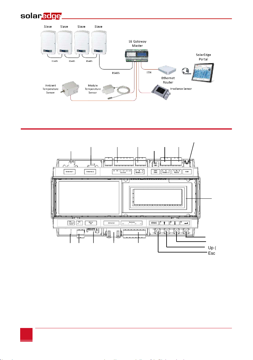
The SolarEdge control and communication gateway expands the SolarEdge monitoring and control
capabilities. It can be connected to SolarEdge and non-SolarEdge inverters, environmental sensors and
revenue meters and can transfer the monitoring data to the SolarEdge monitoring server and optionally,
to a non-SolarEdge logger.
The control and communication gateway can connect to the following devices1:
SolarEdge devices, such as inverters and safety and monitoring interfaces (SMIs)
Non-SolarEdge inverters for inverter data monitoring on the SolarEdge portal
Environmental sensors
Revenue grade meters
3rd party external loggers for inverter data monitoring
Power reduction control devices
NOTE:
Sensors, meters, loggers, and power reduction control devices are sold separately .
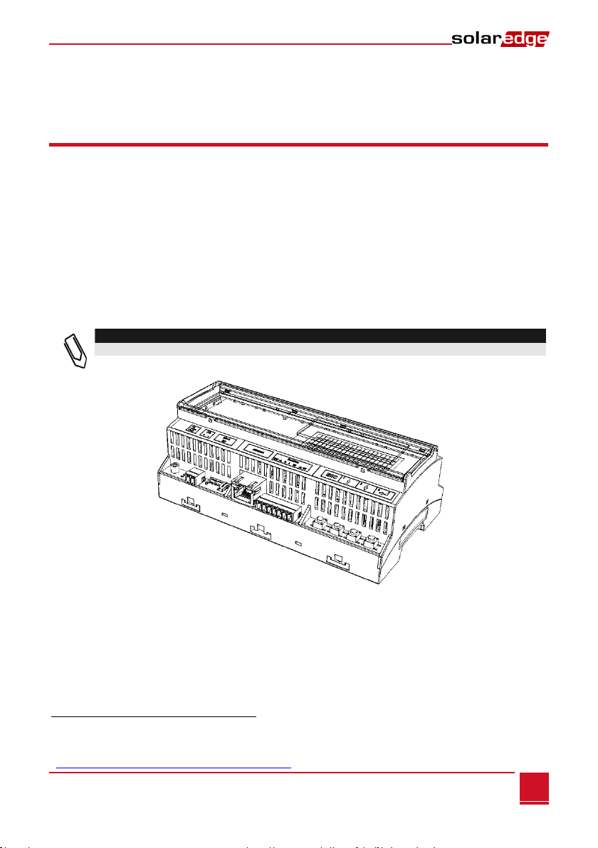
Figure 1: The SolarEdge Control and Communication Gateway
1For a list of supported environmental sensors, revenue meters, and third party inverters, refer to
http://www.solaredge.com/articles/se-supported-devices
Chapter 1: Introducing the SolarEdge Control and Communication Gateway
Control and Communication Gateway Installation Guide - MAN-01-00132-1.2
8
Figure 2: Example of sensor connection to the SolarEdge gateway
Control and Communication Gateway Interfaces
Figure 3: Control and Communication Gateway Interfaces
Esc
Up (1)
Down (2)
Enter (3)
LEDs: DC Micro SD Ethernet Sensors
Green (power
Yellow supply
Red input) LCD Buttons
LCD
Optional Optional
Antenna1 Antenna2 Control RS485-1 SW1 RS485-2 RS232 USB
(ZigBee) SW2
Chapter 1: Introducing the SolarEdge Control and Communication Gateway
Control and Communication Gateway Installation Guide - MAN-01-00132-1.2
9
LCD and LCD-Menu Buttons
The LCD screen displays status information of the SolarEdge gateway and various menus for configuration
options. The LCD panel and buttons are used during the following processes:
Operational Mode: The LCD panel allows checking that the gateway is working properly. Refer to
Status Screens on page 32 for a description of this option. Use the LCD user buttons to toggle
through the informative displays and select options.
Setup: After mounting the gateway, the installer may perform basic gateway configuration, as
described in Setup Menu Options on page 35.
Four buttons are used for controlling the LCD menus (see Figure 3):
Esc: Moves the cursor to the beginning of the parameter, goes to the previous menu and cancels a
value change.
Up (1), Down (2): Moves the cursor between menu options, moves among the characters of a
parameter, and toggles between possible characters when setting a value.
Enter (3): Selects a menu option or accepts a value change. Also used to enable LCD backlight.
LEDs
The front of the SolarEdge gateway has an LCD panel and three LEDs, as shown above:
The gateway has three LED indicators, as follows:
Power OK (Green): Indicates whether or not the SolarEdge gateway is connected to power
Communication (Yellow): This LED blinks when monitoring information is received from another
SolarEdge device in the installation.
Fault (Red): Indicates that there is an error. For more information, contact SolarEdge support.
All LEDs are ON while the SolarEdge gateway is being configured and during power up.
Communication Connectors
Antenna1: used for optional wireless ZigBee or Wi-Fi antenna connection (refer to Wireless ZigBee
Connection and Wi-Fi Connection on page 45.
Antenna2: Currently not installed
RS485-1 and RS485-2: used for connecting external devices to the gateway (refer to Chapter 3:
Connecting the SolarEdge Gateway to the SolarEdge Installation on page 15)
RS232: enables connection of the SolarEdge gateway to an external device using an RS232 interface.
USB: Enables PC/laptop connection for using the SolarEdge configuration tool.
Ethernet: enables connecting the SolarEdge gateway to the SolarEdge monitoring portal through an
Ethernet switch/router (refer to Creating an Ethernet (LAN) Connection on page 42). The Ethernet
switch/router should be connected to the Internet.

Chapter 1: Introducing the SolarEdge Control and Communication Gateway
Control and Communication Gateway Installation Guide - MAN-01-00132-1.2
10
Other Interfaces
DC: used for the power supply input as described in Connecting the SolarEdge Gateway to AC on
page 14.
Sensors: enables connecting to external environmental sensors (refer to Chapter 4: Connecting
Environmental Sensors (Optional) on page 22).
Control: used for connection to an external power reducer device
SW1/SW2: RS485-1/2 termination
Micro SD: used for field software upgrade
Chapter 2: Installing the SolarEdge Gateway
Control and Communication Gateway Installation Guide - MAN-01-00132-1.2
11
Chapter 2: Installing the SolarEdge Gateway
Safety
CAUTION:
For North America only: The product’s communication with external devices, must not use wires
that span more than one building, as per the UL 60950-2 standard.
Transport and Storage
Transport the SolarEdge gateway in its original packaging, without exposing it to unnecessary shocks. If the
original package is no longer available, use a similar box, which can be closed fully.
Store the SolarEdge gateway in a dry place where ambient temperatures are -40°C (-40°F) to
+60°C (140°F).
Package Contents
Control and communication gateway
100-240VAC to 12VDC (50 Hz/60 Hz) power supply with an interchangeable AC plug (US,EU,AU)
Accessory kit including:
Three 3-pin terminal blocks
One 7-pin terminal block
One 6-pin terminal block
Installation Equipment
Standard tools can be used during the installation of the SolarEdge gateway. The following is a
recommendation of the equipment needed for installation:
DIN rails
Drill and 4mm diameter bits
Three twisted wires or four-wire twisted pair cable
For installing the communication options: CAT5/6 Ethernet cable
Chapter 2: Installing the SolarEdge Gateway
Control and Communication Gateway Installation Guide - MAN-01-00132-1.2
12
Installation Guidelines
The following requirements apply when locating and mounting the SolarEdge gateway:
The SolarEdge gateway is suitable for mounting indoors only. For outdoor installation, use an
external outdoor enclosure (not provided by SolarEdge)
The SolarEdge gateway must always remain in an ambient temperature of -20°C (-4°F) to
+60°C (140°F).
Cable specifications:
Connection Type
Cable Type
Maximum Length
RS485 communication bus
(per RS485 port)
Three twisted wires or 4-wire twisted pair
cable (two twisted pairs).
Recommended wire size: 20 AWG / 0.52 mm2
1,000m (3,330 ft)
Ethernet
CAT5/6
100m (325 ft).
Sensor/control interface
Recommended wire size: 20 AWG / 0.52 mm2
50m (165 ft)
The SolarEdge gateway power supply requires a socket outlet with a grid voltage of 100 V - 240 V.
Protect the SolarEdge gateway from dust, wet conditions, corrosive substances and vapors.
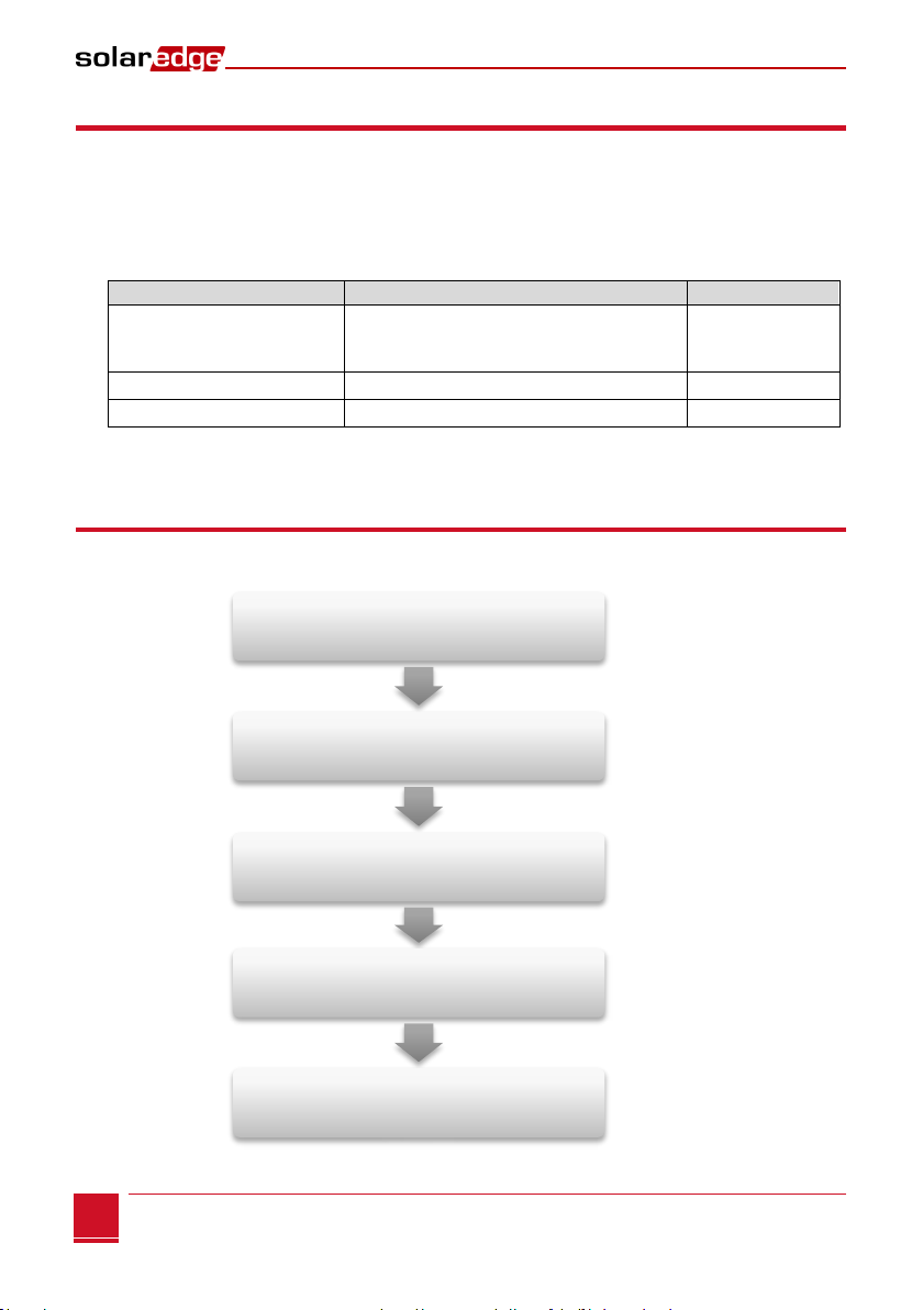
Installation Workflow
The following provides an overview of the workflow for installing and setting up the control and
communication gateway
Step 1
Page 13
Step 2
Page 15
Step 3
Page 22
Step 4
Page 35
Step 5
Page 41
Mounting the control and communication gateway
Connecting the control and communication gateway to
the SolarEdge installation
Connecting envirinmental sensors (optional)
Configuring the
control and communication gateway and inverters/SMI
Using the control and communication gateway to
connect the installation to the monitoring server
(optional)
Chapter 2: Installing the SolarEdge Gateway
Control and Communication Gateway Installation Guide - MAN-01-00132-1.2
13
Mounting and Connecting the SolarEdge Gateway
The SolarEdge gateway can be installed on a wall or on a DIN rail.
►To mount the SolarEdge gateway on a wall:
1Determine the mounting location. Leave clearance from all sides of the SolarEdge gateway for cover
opening, cable connection and routing.
2Open the clips at the rear of the gateway by pushing the clips outwards.
Figure 4: Clips in Open position
3Position the device on the wall with the open clips, as shown in Figure 4. Mark points through the
holes of the clips and drill holes using a 4mm diameter drill bit.
4Mount the unit using screw anchors and screws (use 3.5mm diameter screws, 20mm minimum
length, not provided by SolarEdge).
►To mount the SolarEdge gateway on a DIN rail:
1Ensure that the clips are closed, as shown below:
Figure 5: Clips in Closed position
Wall mount
holes
Press here
Press here
Press here
Press here
Chapter 2: Installing the SolarEdge Gateway
Control and Communication Gateway Installation Guide - MAN-01-00132-1.2
14
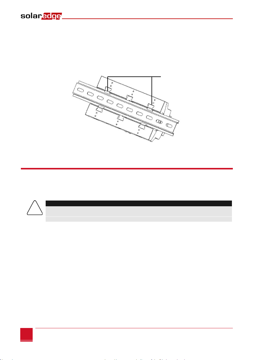
2Hook the two lower clips of the SolarEdge gateway onto the lower edge of the DIN rail.
3Press the SolarEdge gateway upwards and snap it into the upper edge of the DIN rail. When on the
rail, the clip "grips" the rail on both the top and bottom lips of the rail.
To remove the DIN clip from the rail, simply push upwards on the DIN clip (thereby compressing the
springs in the bottom), pivot the top of the clip off of the rail, and then move the whole clip down to
also release the bottom of the clip. No screwdrivers or special tools are required.
4The following figure shows the gateway’s rear side when mounted on a DIN rail.
Figure 6: Gateway mounted on a DIN rail
Connecting the SolarEdge Gateway to AC
For connecting to power, use the supplied power supply:
1Insert the power supply DC connector to the SolarEdge gateway (see Figure 3).
2Connect the power supply to the AC mains. The LEDs are lit momentarily to indicate power
connection (see Figure 3).
CAUTION:
If you use a non-SolarEdge power supply, check that it has 12Vdc/1A output ratings, and that it is
certified to UL/CSA/IEC60950-1 2ed standards. Limited Power Source output, NEC class 2. Verify
the power supply polarity as marked on the gateway.
DIN rail clips
Chapter 3: Connecting the SolarEdge Gateway to the SolarEdge Installation
Control and Communication Gateway Installation Guide - MAN-01-00132-1.2
15
Chapter 3: Connecting the SolarEdge
Gateway to the SolarEdge Installation
Overview
The SolarEdge control and communication gateway connects to the PV system installation using the RS485
communication option. The RS485 option enables creating a chain (bus) of up to 31 slave SolarEdge
devices, connected to one master, which can be another SolarEdge device or the SolarEdge control and
communication gateway.
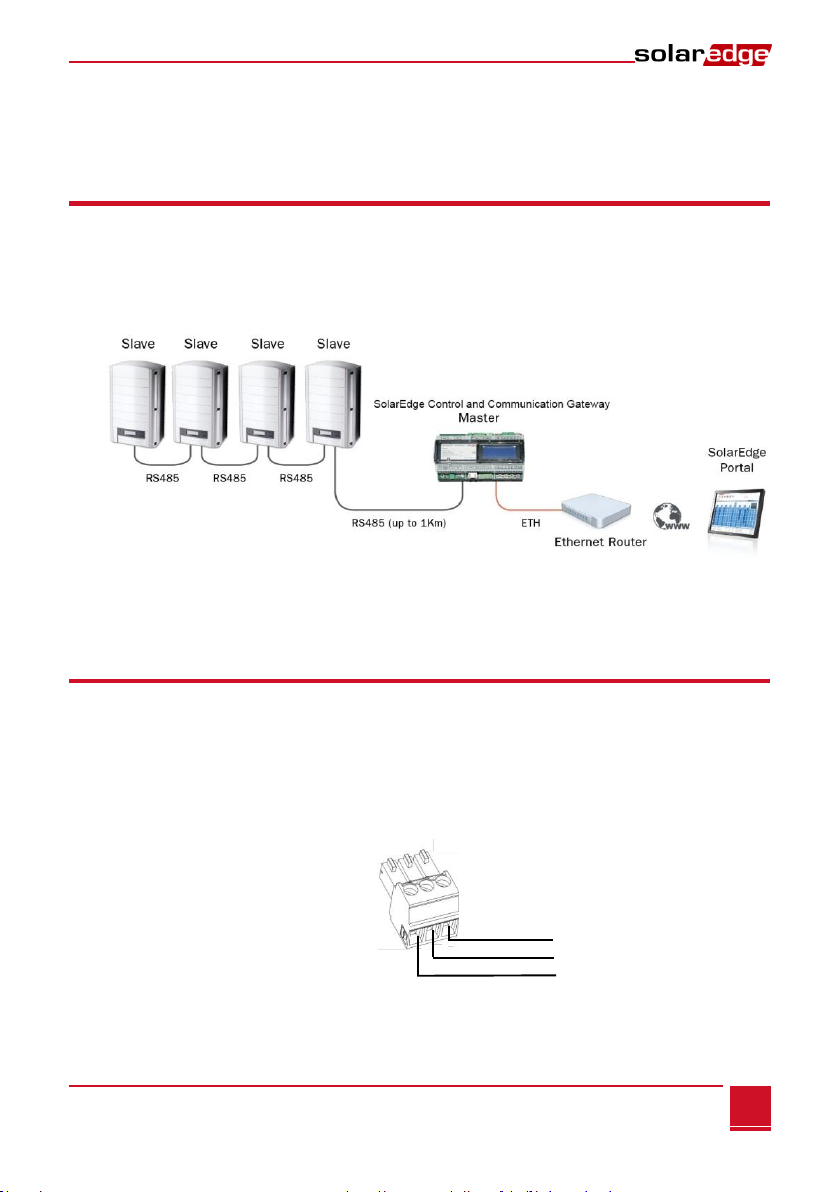
The following is an example of a master gateway connected to a chain of slave inverters.
Figure 5: Example of RS485 connection
The following sections describe how to connect the RS485 bus and how to configure its components.
Connecting and Configuring the RS485
The RS485 bus uses a three-wire cable connecting the RS485-1/2 terminal blocks on the SolarEdge
gateway to the RS485 input of the inverters/SMI.
►To connect the RS485 communication bus between inverters/SMIs and
SolarEdge gateway:
1Use one of the supplied 3-pin terminal blocks: Loosen the screws and insert the wire ends into the
A, Band G pins. For connections longer then 10m use twisted pair wires for A and B wires.
Figure 7: 3-pin terminal block
Terminated
(Terminated)
G
B
A

Chapter 3: Connecting the SolarEdge Gateway to the SolarEdge Installation
Control and Communication Gateway Installation Guide - MAN-01-00132-1.2
16
2Choose either RS485-1 or RS485-2 for connection. Connect the 3-pin terminal block to the designated
port on the gateway.
NOTE:
RS485-1 is configured as SolarEdge device by default, therefore RS485-1 is recommended as
the RS485 bus connection point.
3If the gateway is at the end of the RS485 chain, terminate the gateway by switching a termination
dipswitch to ON. The switches in the SolarEdge gateway are marked SW1 for the RS485-1 port
termination and SW2 for the RS485-2 port termination, as shown below:
Figure 8: RS485 connectors and termination switches
4Open the inverter/SMI cover as described in their manual.
5Remove the seal from one of the openings in communication gland #2 of the inverter and insert the
cable through the opening.
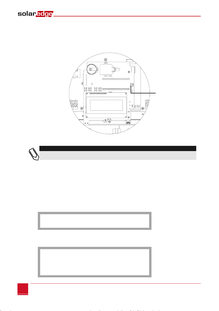
6Pull out the 9-pin RS485/RS232 terminal block connector, as shown below:
Figure 9: The RS485/RS232 terminal block in the inverter/SMI
On Off
A B G
A B G
SW1 SW2
RS485- 2 RS485-1

Chapter 3: Connecting the SolarEdge Gateway to the SolarEdge Installation
Control and Communication Gateway Installation Guide - MAN-01-00132-1.2
17
7Loosen the screws of pins B, Aand Gon the left of the RS-485 terminal block:
For inverter: RS485-1 pins (left-most)
For SMI: RS485-1 (recommended, as this is the default configuration), or RS485-2
Figure 10: RS485/RS232
8Insert the ends of wires into the G, Aand B pins shown above. You can use any color wire for each of
the A, B and G connections, as long as the same color wire is used for all A pins, the same color for all
B pins and the same color for all G pins.
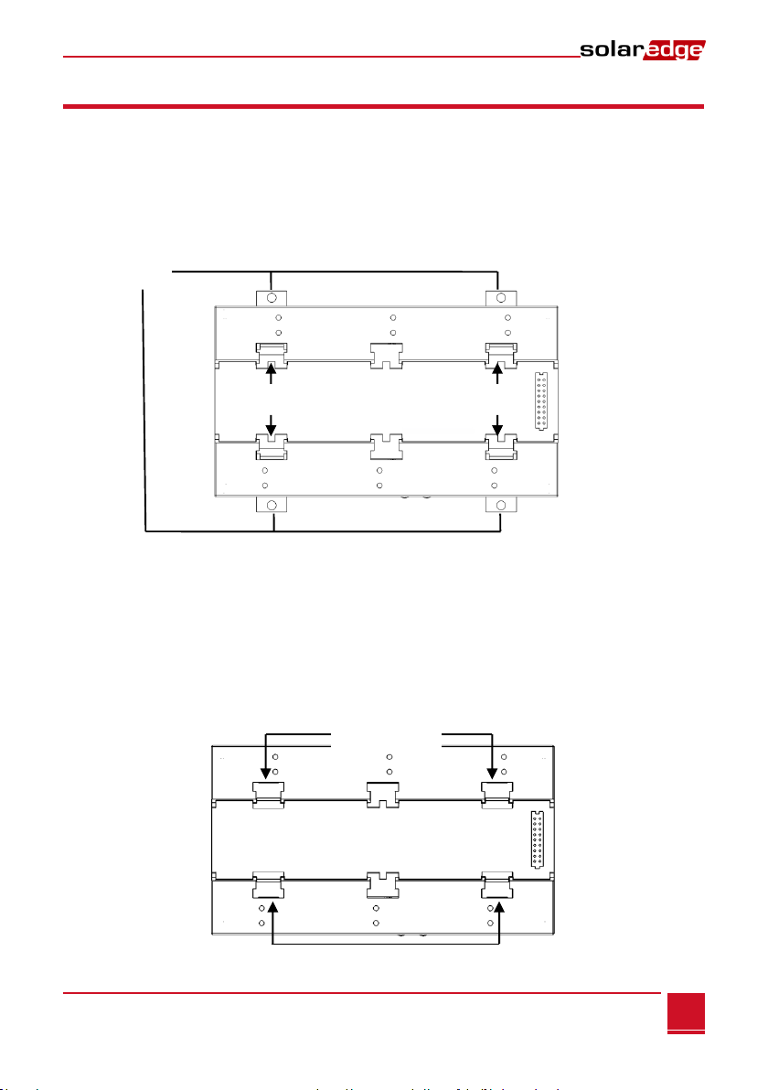
9Connect all B, Aand Gpins in all inverters/SMI. The following figure illustrates this connection
schema (the illustration applies to both inverters and SMI):
Figure 11: Connecting SolarEdge devices (inverters or SMI) in a chain
NOTE:
Do not cross-connect B, Aand G wires.
For inverters - Do not insert wires into RS485-2 pins.
RS485-2 (used in SMI only)
RS485-1
G
A
B
G
A
B
Screws
SolarEdge Gateway
Chapter 3: Connecting the SolarEdge Gateway to the SolarEdge Installation
Control and Communication Gateway Installation Guide - MAN-01-00132-1.2
18
10 Tighten the terminal block screws.
11 Push the RS485 terminal block firmly all the way into the communication board.
12 Terminate the inverters/SMIs at the two ends of the chain by switching a termination dipswitch
inside the inverter/SMI to ON (move the switch to the top). The switch is located on the
communication board and is marked SW7.
Figure 12: RS485 termination switch
NOTE:
Only the first and last SolarEdge devices in the chain should be terminated. The other devices in
the chain should have the termination switch OFF.
►To configure the RS485 communication bus with SolarEdge inverters/SMI:
By default, all SolarEdge devices are pre-configured as slaves. Slaves can be further configured using the
RS485-x Conf option in the Communication menu.
One device must be set as the master on the RS485 bus. Any one of the SolarEdge devices may be the
master (control and communication gateway, inverter, or SMI). If you connect the installation to the
SolarEdge monitoring portal, the device used to connect to the server must be the master.
The following describes how to configure the master device.
1Press the Enter button until the following message is displayed:
P l e a s e ente r
P a s s w o r d
* * * * * * * *
The gateway is now in Setup mode and all its LEDs are lit.
2Use the three-right-most LCD buttons to type in the following password: 12312312. The following
menu is displayed:
L a n g u a g e < e n g >
Communication
Sensors
Display
Maintenance
Information
Use the left switch
Chapter 3: Connecting the SolarEdge Gateway to the SolarEdge Installation
Control and Communication Gateway Installation Guide - MAN-01-00132-1.2
19
3Short-press the arrow buttons to scroll to the Communication menu. Press the Enter key to select it.
4Select Server RS485-X Conf (X=1 or 2 depending on the specific physical port connection) to
communicate with different external devices (SolarEdge inverters, revenue meters, non-SolarEdge
loggers or non-SolarEdge inverters).
5To configure the master, select the following in the LCD menus:
Communication RS485-1 Conf Device Type SolarEdge
RS485-1 Conf Protocol Master
RS485-1 Conf Slave Detect
The system starts automatic detection of the SolarEdge slave inverters connected to the master
gateway. The gateway should report the correct number of slaves. If not, verify the connections and
terminations. Verify that only one master is configured on the bus.
6Close the inverter/SMI cover and start power production.
7Verify the connection of the Master to the SolarEdge monitoring portal, as described in Verifying the
Connection, below.
Verifying the Connection
1After connection, a message similar to the following appears in the main status screen (see also
Initial Gateway Status on page 32:
RRCR:Diabled
Sensors:Disabled
S e r v e r : L A N < S _ O K >
T o t a l # o f S l a v e s : --
2Verify that S_OK appears, to indicate that the connection to the SolarEdge monitoring portal is
successful. If S_OK is not displayed, refer to Troubleshooting Communication, below.
Troubleshooting the RS485 Communication
1If No Communication is displayed on the SolarEdge gateway, perform the following:
Verify that the RS485 cable is connected to all inverters. Check the connections between the
first inverter in the chain and the other inverters.
Verify that one of the devices is defined as the master and that slaves were detected, as
described in Step 5 above.
2Check the Server Communication Status screen of all the inverters. The following should appear:
Server:RS485
S t a t u s : O K
If the message Master Not Found, check the connections to the master device and fix if required.
Table of contents
Other SolarEdge Gateway manuals


Popular Gateway manuals by other brands


ZyXEL Communications
ZyXEL Communications ADSL2+ 4-port Gateway P-660H-D Series user guide

Amaranten
Amaranten F1800 Series Installation and setup guide

Extron electronics
Extron electronics ShareLink 200 Setup guide

RTA
RTA 460MCMRS-NNA1 Product user guide

ZKTeco
ZKTeco SLG410 quick start guide

ORiNOCO
ORiNOCO BG-2000 user manual