Duevi RX2 AP User manual

RX2 AP
2 CHANNELS WIRELESS RECEIVER
INSTRUCTION MANUAL
(VERSION 2.4)
We thank you very much for choosing our product.
Now we would like to invite you to read carefully the following
instructions before installing the product in order to use all its capacities.
This electronic device is compliant to the essential requirements of the
European Union (EU) norms, concerning the electromagnetic compatibility
and the electric safety.

This manual can be modified without any advice
2 RX2AP V2.4
RX2 AP: 2 channels wireless receiver
Warning: THE INSTALLER TECHNICIAN MUST FOLLOW THE NORMS OF THE COUNTRY
WHERE THE PRODUCT IS INSTALLED. DUEVI DECLINES ANY RESPONSIBILITY IN CASE OF
IMPROPER USE OF THE CUSTOMER OR WRONG INSTALLATION.
DO NOT INSTALL THE DEVICE IN HUMID LOCATIONS OR EXPOSED TO EXTREME
TEMPERATURES. FOR A SOLID AND RELIABLE IMPLANTATION IT IS INDISPENSABLE TO
MAKE SURE THAT THE SURFACE OF THE WALL IS FLAT. FIX THE DEVICE AT AN HEIGHT
THAT ALLOWS AN EASY ACCESS FOR THE USER. INSTALL THE DEVICE IN A LOCATION
COVERED BY A VOLUMETRIC DETECTOR.
DUEVI DECLINES ANY RESPONSIBILITY IN CASE OF IMPROPER USE OF THE CUSTOMER.
EVENTUAL MODIFICATIONS CARRIED OUT FROM NOT SPECIALIZED STAFF CAN DAMAGE
THE DEVICE.
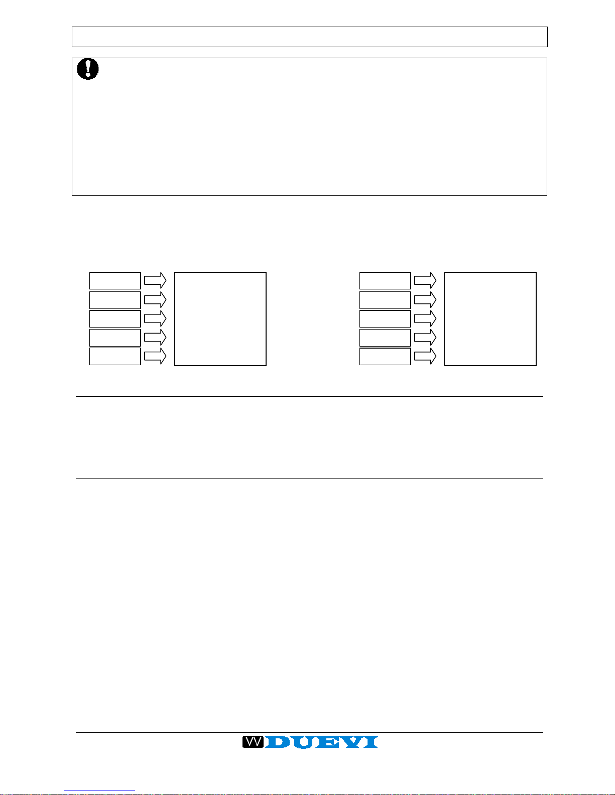
RX2 AP is a 2 channels self-learning receiving device with 2 independent relay outputs. Each channel may
store up to 5 wireless devices (sensors and remote controls). Each channel is related to a relay output with
voltage-free contacts, that can be used as needed.
The device, enclosed in a plastic case, has an integrated antenna and allows to use wired control panels with
the Duevi series wireless detectors.
1. MEMORY TOTAL RESET
Before using the receiver, it is advisable to make a total reset of the memory, in order to delete any codes that
may be programmed in factory test.
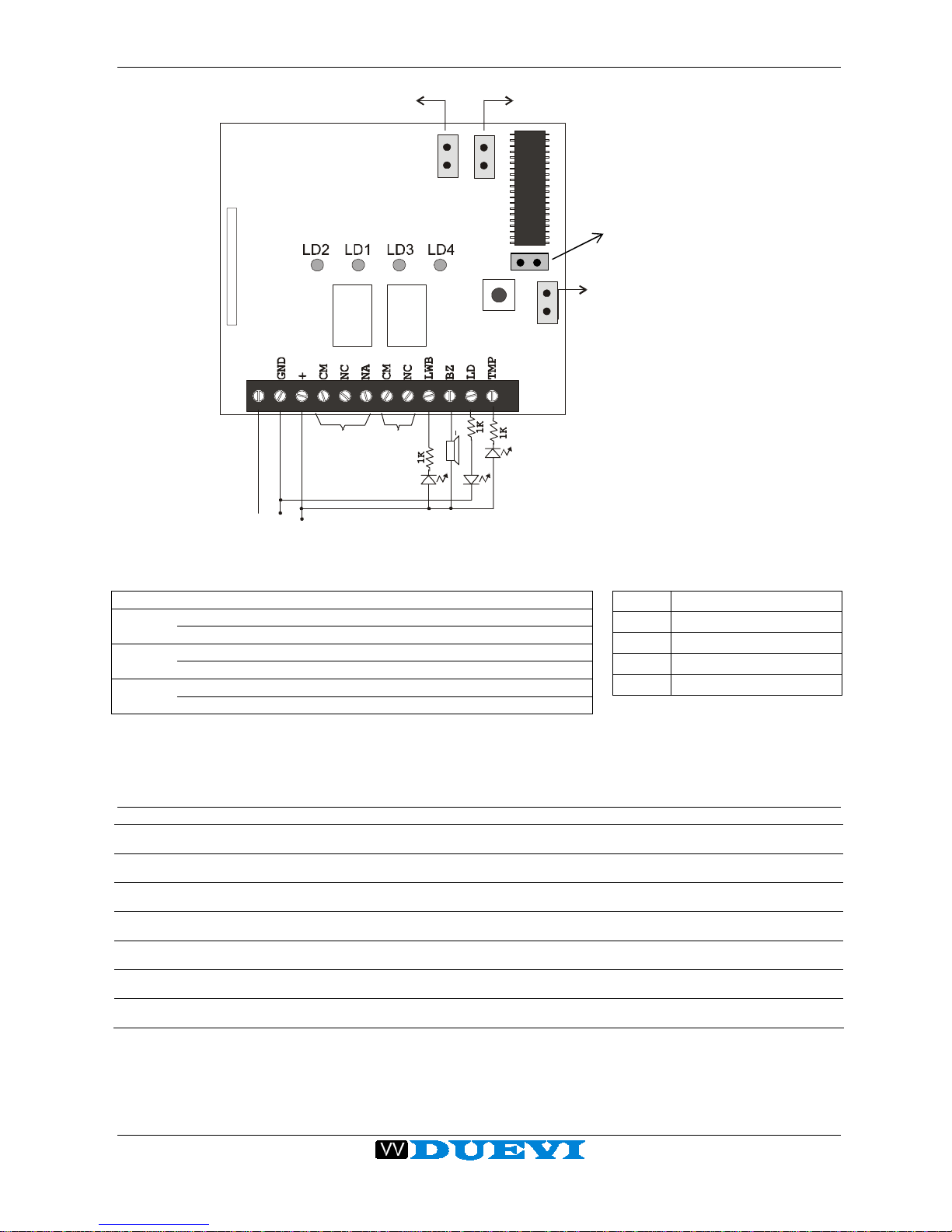
Press and maintain pressed the button S1 while giving power supply to the device. Continue to press the
button until, after about 5 seconds, you will ear 3 short beeps followed by a long one. Now you can release the
button. The Reset is completed.
2. WIRELESS CODE PROGRAMMING
To enter in this mode, you have to close the jumper JP2.
The device will emits 2 beeps and will light on Ld3, meaning it is positioned on the channel 1 (RL1);
furthermore if the memory position is empty it will light on also Ld1, otherwise if it is occupied will light on Ld2.
Now the receiver is positioned on the Code 1.
To select the following Code, press shortly S1. You will ear as many beep as the number of the Code (Code2 =
2 beep, Code3 = 3 beep).
After the 5 Codes related to Channel 1, the device pass to the 5 Codes related to Channel 2 (Ld3 will turn off
and Ld4 turns on).
If you want to store a detector or a remote control on the selected Code Position, press for few seconds S1
until Ld2 will light on (or Ld1 turns off). Now the receiver is waiting for a wireless code; transmit with the sensor
or the remote control to be programmed.. The receiver confimrs the code memorization with the blinking of
Ld3.
Repeat this programming operation for any wireless device to be programmed on the receiver, than open the
jumper JP2 in order to exit from Programming mode.
Code 1
Channel 1
Relay RL1
Code 2
Code 3
Code 4
Code 5
Code 1
Channel 2
Relay RL2
Code 2
Code 3
Code 4
Code 5

This manual can be modified without any advice 3
RX2AP V2.4
3. “ONLY REMOTE CONTROLS” MODE (jumper C13 closed)
In this working mode, the TXS remote controls are the only device that is considered by the receiver.
Even if other devices are allowed to be programmed, that devices will be completely ignored by the
receiver. It is possible to program up to 10 TXS remote controls, selecting than with the jumper JP3 the
working mode of both the channels (RL1 and RL2).
JP3 closed = BISTABLE OUTPUTS
Pressing Red Key, the RL1 is armed – Pressing again the RL1 is disarmed
Pressing Green Key, the RL2 is armed – Pressing again the RL2 is disarmed
JP3 open = IMPULSIVE OUTPUTS
Pressing Red Key, the RL1 is armed and after 2 seconds automatically disarmed
Pressing Green Key, the RL2 is armed and after 2 seconds automatically disarmed
4. SENSORS MODE (jumper C13 open)
In this working mode it is possible to use both sensors and remote controls, selecting with the jumper JP3 the
working mode of the Channel 1 (RL1) with remote controls.
JP3 closed = RL1 BISTABLE OUTPUT
Pressing Red Key the RL1 is armed – Pressing Green Key the RL1 is disarmed
JP3 open = RL1 IMPULSIVE OUTPUT
Pressing any key of the remote control the RL1 is armed and after 2 seconds automatically disarmed
IMPORTANT NOTICE: The working mode of the relay outputs (RL1 and RL2) with the SENSORS is
always IMPULSIVE, even if JP3 is closed. For every transmission of sensor, the receiver will arm the
corresponding output relay and than disarm after 2 seconds.
5. TSR MODE
It is possible to use the reciever also with the 48bit TSR (Siren transmitter). To program the TSR code it is
sufficient to press the tx tamper button on the TSR.
The receiver works in different modes, depending on the setting of the jumper JP3.
JP3 closed = BISTABLE OUTPUTS
Channel1 (RL1) is armed when TSR transmits an “ARM” code, disarmed when it transmits a “DISARM” one.
Channel2 (RL2) is armed for 2 seconds when TSR transmits an “ALARM” code
JP3 open = IMPULSIVE OUTPUTS
Channel1 (RL1) is armed for 2 seconds when TSR transmits an “ALARM” code
Channel2 (RL2) is armed for 2 seconds when TSR transmits a “DISARM” code
IMPORTANT NOTICE
The RX2AP receiver works properly
ONLY with the new family of device with suffix 100;
for example CTSR-100 / DIRRV-100 / TXS-100 etc.

This manual can be modified without any advice
4 RX2AP V2.4
6. CONNECTING DIAGRAM
Reset
JP3
JP2
Relè1
Relè2
ricevitore
MICROPROCESSORE
antennafilo18cm
out RL1 out RL2
buzzer
+
-GND
+12V
JP2 chiuso = apprendim.
JP2 aperto = normale JP3 chiuso = canale1 bistabile
JP3 aperto = canale 1 monostabile
JP1
JP1 chiuso = 12 bit
JP1 aperto = 48 bit
JP1 LEAVE ALWAYS OPEN
JP2 open Working Mode
closed Programming Mode
JP3 open Impulsive Outputs
closed Bistable Outputs
C13 open Sensor and Remote Controls MODE
closed ONLY Remote Controls MODE
7. TECHNICAL FEATURES
CHANNELS 2 alarm channels, with selectable impulsive or bistable working mode
OUTPUTS 2 relays, one per channel.
BUZZER OUTPUTS for acoustic test of wireless range
RANGE 100m in open field
FREQUENCY >430 MHz
POWER SUPPLY 12 Vdc - 15 mA
DIMENSIONS 150 x 100 x 45 mm
C13 open = sensors and remote controls
C13 closed = ONLY remote controls
S1
C13
Lighted on
LD1 Free Position
LD2 Occupied Position
LD3 Channel 1
LD4 Channel 2
JP2 closed = programming
JP2 open = working JP3 closed = bistable outputs
JP3 o
p
en = im
p
ulsive out
p
uts
JP1 ALWAYS OPEN
Table of contents
Other Duevi Receiver manuals