manuals.online logo
Brands
  1. Home
  2. •
  3. Brands
  4. •
  5. Duevi
  6. •
  7. Receiver
  8. •
  9. Duevi RX2AP Guide

Duevi RX2AP Guide

This manual is subject to modification without advice
MADE IN ITALY
THE INSTALLER HAS TO FOLLOW REGULATIONS. INTERVENTIONS MADE BY NOT AUTHORIZED STAFF CAN DAMAGE THE DEVICE.
THE PRODUCER IS NOT RESPONSIBLE IN CASE OF IMPROPER USE OR WRONG INSTALLATION.
DO NOT INSTALL THE RECEIVER IN DUMP PLACES OR EXPOSED AT HIGH/LOW TEMPERATURES OR INCLEMENCY OF THE WEATHER.
FOR MORE SAFETY, INSTALL THE RECEIVER IN A PLACE PROTECTED BY AN ALARM DETECTOR.
RX2AP is a receiver that can store up to 10 radio codes (auto-learning) combined to 2 independent outputs (5 radio codes each): the outputs are dry-contact relay type.
It is possible to learn the radio codes of sensors, remote controls or special transmitters (TSR) for control panels.
This device allow a simple interface between wired control panels and wireless sensors or remote controls.
INDEX
1. RESET ................................................................................................................................................................................................................................................ 1
2. TECHNICAL ........................................................................................................................................................................................................................................ 2
3. LEARNING ......................................................................................................................................................................................................................................... 2
4. “SENSORS + REMOTE CONTROLS” MODE DIP1 = OFF | DIP3 = OFF | DIP4 = OFF.............................................................................................................................. 3
5. “REMOTE CONTROLS” MODE DIP1 = OFF | DIP3 = OFF | DIP4 = ON ................................................................................................................................................. 3
6. “LIGHT TIMER” MODE DIP1 = OFF | DIP3 = ON | DIP4 = OFF ............................................................................................................................................................ 4
7. USE OF THE TSR TRANSMITTER DIP1 = OFF | DIP3 = OFF | DIP4 = OFF.............................................................................................................................................. 4
1. RESET
The following procedure bring back the receiver to factory settings. It is necessary to run the reset before start programming and use the device.
1. Remove power to the receiver (wait about 1 minute the circuit discharges)
2. Hold down the Pbutton while powering the receiver
3. After about 5 seconds the receiver emits three quick “beep”followed by one long one
4. Release the Pbutton. The reset is complete.
RX2AP
TWO OUTPUTS RADIO RECEIVER
[AN] Installation and use manual 15.10-M:4.1-H:x.x-F:F9D0
Radio Zone A-1
RELAY A
Radio Zone A-2
Radio Zone A-3
Radio Zone A-4
Radio Zone A-5
Radio Zone B-1
RELAY B
Radio Zone B-2
Radio Zone B-3
Radio Zone B-4
Radio Zone B-5
Matching scheme of Radio
Zones with Relay Outputs:
2
2. TECHNICAL
RELAY OUTPUTS
2 alarm relays (mono-stable or bi-stable working modes)
MAX: 24 V / 500 mA
SIGNALLING
Buzzer on board for operation feedback (not excludible)
4 internal LEDs for operation feedback (2 LEDs for relay outputs state, 2 LEDs for Radio Zones management)
RADIO RECEIVER
Working frequency: 433.92 MHz –Radio code format: 48 bit
POWER SUPPLY
12 V / MAX 25 mA
WARNING > The receiver must be powered by a very low voltage power source (SELV)
DIMENSION
120 x 85 x 28 mm
COMPATIBILITY
Sensors (only AN models): MINI-M, MINI-C, CTSR, DIRRV2, DIRRPV, DSA, DSF, E-WALL, DIRRVE, DIRRVE-DT, MOSKITO
Remote controls: TXS/M
Siren Transmitters: TSR
3. LEARNING
LED_A
Yellow
LED_B
Green
LED_X
Blue
LED_O
Red
1
To enter in learning mode set DIP1 to ON. Two “beep” are emitted
2x BEEP
2
LED_A lights on meaning the receiver is in memory space for Relay A (Radio Zones A-1 ÷ A-5).
The receiver starts from Radio Zone A-1. If the memory position is empty the LED_O(free memory) lights on, if
occupied the LED_X (used memory, it is possible to overwrite) lights on.
OR
3
To go to the next Radio Zone, press P.
As confirm the receiver emits as many “beep” as the Radio Zone number (Radio Zone A-2 = 2 “beep”, Radio
Zone A-3 = 3 “beep”…).
1x BEEP … 5x BEEP
DIP1
OFF
Normal working
ON
LEARNING (pairing of radio devices)
DIP2
OFF
Relay A = Monostable
ON
Relay A = Bistable
DIP3
OFF
Normal working
ON
“LIGHT TIMER”mode
DIP4
OFF
“Sensors + Remote controls” mode or use with TSR
ON
“Remote controls”mode
+12
Power supply: positive reference +12V
GND
Power supply: ground/negative reference
C1
Relay A: common terminal
NC1
Relay A: Normally Closed terminal
NA1
Relay A: Normally Opened terminal
C2
Relay B: common terminal
NC2
Relay B: Normally Closed terminal
LD
LED output: combined to Relay A activation
Output at +12V when the Relay A is active –Output at zero when Relay A is at rest.
Useful to visualize (using a TSR) the arming status of a control panel.
TMP
TAMPER output, Open Collector –Close to negative to signal the reception of a
tamper radio code from a sensor. In case of tamper alarm, also the Relay output
combined to the sensor will be activated.
LWB
LOW BATTERY output (sensors), Open Collector –Close to negative to signal the
reception of a Low Battery code from a sensor.
3
4
To learn a sensor/remote control/TSR in selected memory space:
hold down the Pbutton for 3 seconds
the LED_X or LED_O light on (depending on which one was already on): the receiver is now waiting
make the sensor *(only AN code, see sensor manual), the remote control or the TSR transmitter (only
disarming) transmit
the receiver confirms the learning of the code by blinking 2 times the LED_A, and emits 2 “beep”. The
LED_O switches off but the LED_X (occupied memory)
5
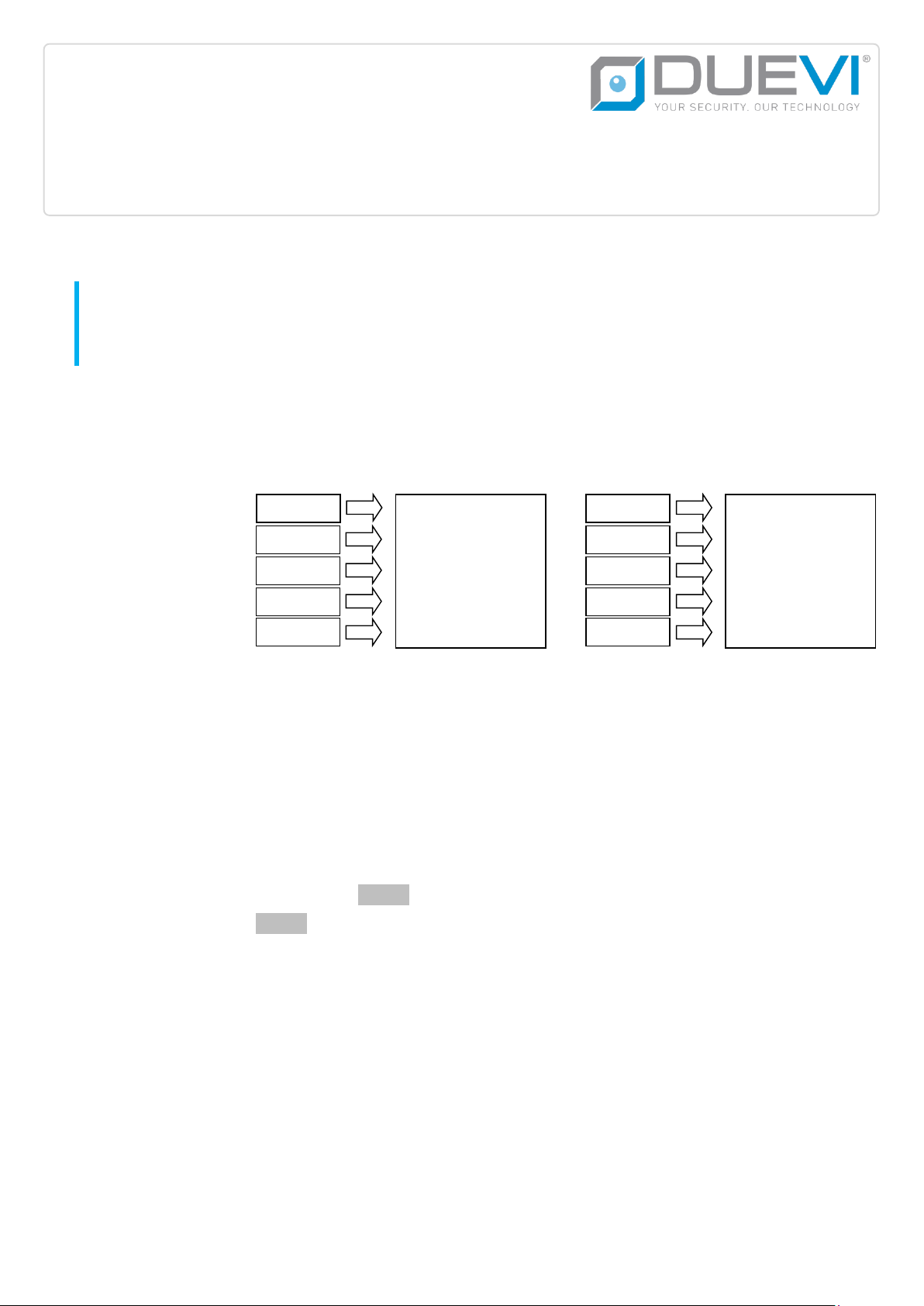
After the Radio Zones for Relay A, there are the ones for Relay B (Radio Zones B-1 ÷ B-5).
The LED_A switches off and the LED_B lights on meaning the receiver is in memory space for Relay B.
The receiver starts from Radio Zone B-1. If the memory position is empty the LED_O(free memory) lights on,
if occupied the LED_X (used memory, it is possible to overwrite) lights on.
OR
6
To go to the next Radio Zone, press P.
As confirm the receiver emits as many “beep” as the Radio Zone number (Radio Zone B-2 = 2 “beep”, Radio
Zone B-3 = 3 “beep”…).
1x BEEP … 5x BEEP
7
To learn a sensor/remote control in selected memory space:
hold down the Pbutton for 3 seconds
the LED_X or LED_O light on (depending on which one was already on): the receiver is now waiting
make the sensor *(only AN code, see sensor manual) or the remote control transmit
the receiver confirms the learning of the code by blinking 2 times the LED_B, and emits 2 “beep”. The
LED_O switches off but the LED_X (occupied memory).
8
When finished to learn peripherals set DIP1 to OFF
*Generally, to transmit an AN code press the TAMPER switch of the sensor. To learn the DSF (smoke) sensor, hold down the TEST button for some seconds. Read the manuals of each
product for further information.
4. “SENSORS + REMOTE CONTROLS”MODE DIP1 = OFF | DIP3 = OFF | DIP4 = OFF
In this mode both sensors and remote controls work: the remote controls must be stored only in Relay A zones (Radio Zones A-1 ÷ A-5).
Set the working mode of the Relay A (for remote controls) with DIP2:
DIP2 = ON RELAY A BI-STABLE
The sensors must be stored only in Relay B zones (Radio Zones B-1 ÷ B-5).
By pressing the BIG button of a remote control, the Relay A is activated –pressing the SMALL button the Relay A releases
The Relay B is activated for 2 seconds when it is received an alarm code from a sensor stored in Radio Zones B
DIP2 = OFF RELAY A MON-OSTABLE
The sensors can be stored in both memory zones of Relay A and Relay B.
By pressing any button of a remote control the Relay A is activated for 2 seconds (then release)
The Relay B is activated for 2 seconds when it is received an alarm code from a sensor stored
5. “REMOTE CONTROLS”MODE DIP1 = OFF | DIP3 = OFF | DIP4 = ON
In this mode only the remote controls work: the remote controls must be stored only in Relay A zones (Radio Zones A-1 ÷ A-5). Do not store sensors (they will be ignored
by receiver). Set the working mode of the Relay A with DIP2:
DIP2 = ON BI-STABLE
By pressing once the BIG button of a remote control, the Relay A is activated –Pressing it again, the Relay A releases
By pressing once the SMALL button of a remote control, the Relay B is activated –Pressing it again, the Relay B releases
DIP2 = OFF MONO-STABLE
By pressing the BIG button of a remote control the Relay A is activated for 2 seconds (then release)
By pressing the SMALL button of a remote control the Relay B is activated for 2 seconds (then release)
4
6. “LIGHT TIMER”MODE DIP1 = OFF | DIP3 = ON | DIP4 = OFF
This mode (DIP3 = ON) set the receiver to maintain active the Relay outputs for 3 minutes (useful as light timer) when it is received a radio code from a remote control,
a sensor or the “alarm”code of a TSR. The remote controls and TSR transmitters must be stored only in Relay A zones (Radio Zones A-1 ÷ A-5).
During this time the receiver will not react to any command.
DIP2 = ON BI-STABLE
By pressing once the BIG button of a remote control, the Relay A is activated –Pressing it again, the Relay A releases
The Relay B is activated for 3 minutes when it is received an alarm code from a sensor stored in Radio Zones B (the sensors stored in Radio Zones A are
ignored)
DIP2 = OFF MONO-STABLE
The Relay A is activated for 3 minutes when it is received a radio code (sensor, remote control or TSR “start alarm”) from Radio Zones A
The Relay B is activated for 3 minutes when it is received an alarm code from a sensor stored in Radio Zones B
7. USE OF THE TSR TRANSMITTER DIP1 = OFF | DIP3 = OFF | DIP4 = OFF
The receiver can be paired with TSR (transmitter for sirens) to visualize from remote the alarm system status.
The TSR transmitters must be stored only in Relay A zones (Radio Zones A-1 ÷ A-5). The remote controls must be stored only in Relay A zones (Radio Zones A-1 ÷ A-5).
The receiver works differently depending on DIP2 setting:
DIP2 = ON BI-STABLE
The Relay A is activated when it is received the “ARM”code of a TSR, and releases when it is received the “DISARM”code
By pressing once the BIG button of a remote control, the Relay A is activated –Pressing it again, the Relay A releases
By pressing once the SMALL button of a remote control, the Relay B is activated –Pressing it again, the Relay B releases
The Relay B is activated for 2 seconds when it is received the “START ALARM”code of a TSR or an alarm code of a sensor stored in Radio Zones B
DIP2 = OFF MONO-STABLE
The Relay A is activated for 2 seconds when it is received an “ALARM”code of a TSR or any code of a remote control or an alarm code of a sensor stored in
Radio Zones A
The Relay B is activated for 2 seconds when it is received a “STOP ALARM”or “DISARM”codes of a TSR or an alarm code of a sensor stored in Radio Zones B
This device meets the R&TTE requirements (European Union)

Other Duevi Receiver manuals

Duevi RX808-LCD Guide

Duevi

Duevi RX808-LCD Guide

Duevi SINT-13 Guide

Duevi

Duevi SINT-13 Guide

Duevi RX2 AP User manual

Duevi

Duevi RX2 AP User manual

Popular Receiver manuals by other brands

Lehmann electronic VarioRec 6 Quick reference guide

Lehmann electronic

Lehmann electronic VarioRec 6 Quick reference guide

Sealey RS1.V3 instruction manual

Sealey

Sealey RS1.V3 instruction manual

Teleco TVRGBDU868DT24 manual

Teleco

Teleco TVRGBDU868DT24 manual

Yamaha RX-V471 owner's manual

Yamaha

Yamaha RX-V471 owner's manual

DTC SOL8SDR-R Hardware guide

DTC

DTC SOL8SDR-R Hardware guide

AJA IPR-10G2-HDMI Installation and operation guide

AJA

AJA IPR-10G2-HDMI Installation and operation guide

Ross HDR-6110USB user manual

Ross

Ross HDR-6110USB user manual

Daikin iTM plus installation manual

Daikin

Daikin iTM plus installation manual

Onkyo TX-SR494DAB Initial setup guide

Onkyo

Onkyo TX-SR494DAB Initial setup guide

XHDATA D-808 instruction manual

XHDATA

XHDATA D-808 instruction manual

Midian Electronics TTC-1 manual

Midian Electronics

Midian Electronics TTC-1 manual

FUTABA R6303SBE quick start guide

FUTABA

FUTABA R6303SBE quick start guide

Orava RCD-811 instruction manual

Orava

Orava RCD-811 instruction manual

Onkyo HT-R695 Basic Manual

Onkyo

Onkyo HT-R695 Basic Manual

Sherwood RD-6108 owner's manual

Sherwood

Sherwood RD-6108 owner's manual

technetix AIMA3000 user manual

technetix

technetix AIMA3000 user manual

Becker Centronic VarioControl VC360-II Assembly and operating instructions

Becker

Becker Centronic VarioControl VC360-II Assembly and operating instructions

Sony AC-U50A operating instructions

Sony

Sony AC-U50A operating instructions

manuals.online logo
manuals.online logoBrands
  • About & Mission
  • Contact us
  • Privacy Policy
  • Terms and Conditions

Copyright 2025 Manuals.Online. All Rights Reserved.