3 … 16
Printed in Germany • Rösler Druck • Edition 02.08 • Nr. 240 164
Overview
• Microprocessor-based electronics
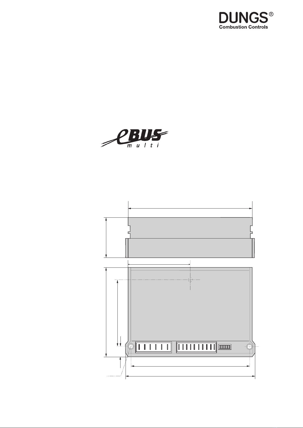
• Installation in housing to IP20
• Connection system with RAST 5 and
RAST 2.5 plug-in connectors
• 24 VDC/25 mA power supply for
powering external current level
converters
• Selectable input for power actuator
signals either as voltage input of
0...10 V/2...10 V or as current input
of 0...20 mA/4...20 mA.
• 0...10 V/2...10 V output
• 0...20 mA/4...20 mA output
• Integrated eBUS connection
• “Four-wire eBUS” connection (TTL
level) for connecting automatic burner
control systems without fully integra-
ted eBUS connection
• Connection for external display unit
for instrument parameterising
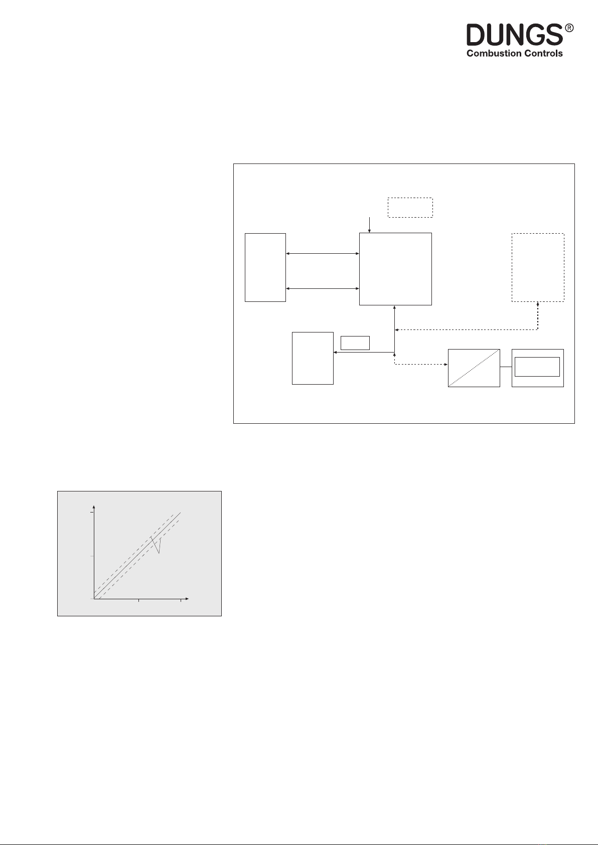
DLU 02 Dungs power converter for coupling controllers and DDC systems with eBUS-compatible auto-
matic burner control systems
The Dungs DLU 02 power converter has the following functions:
Schematic Diagram
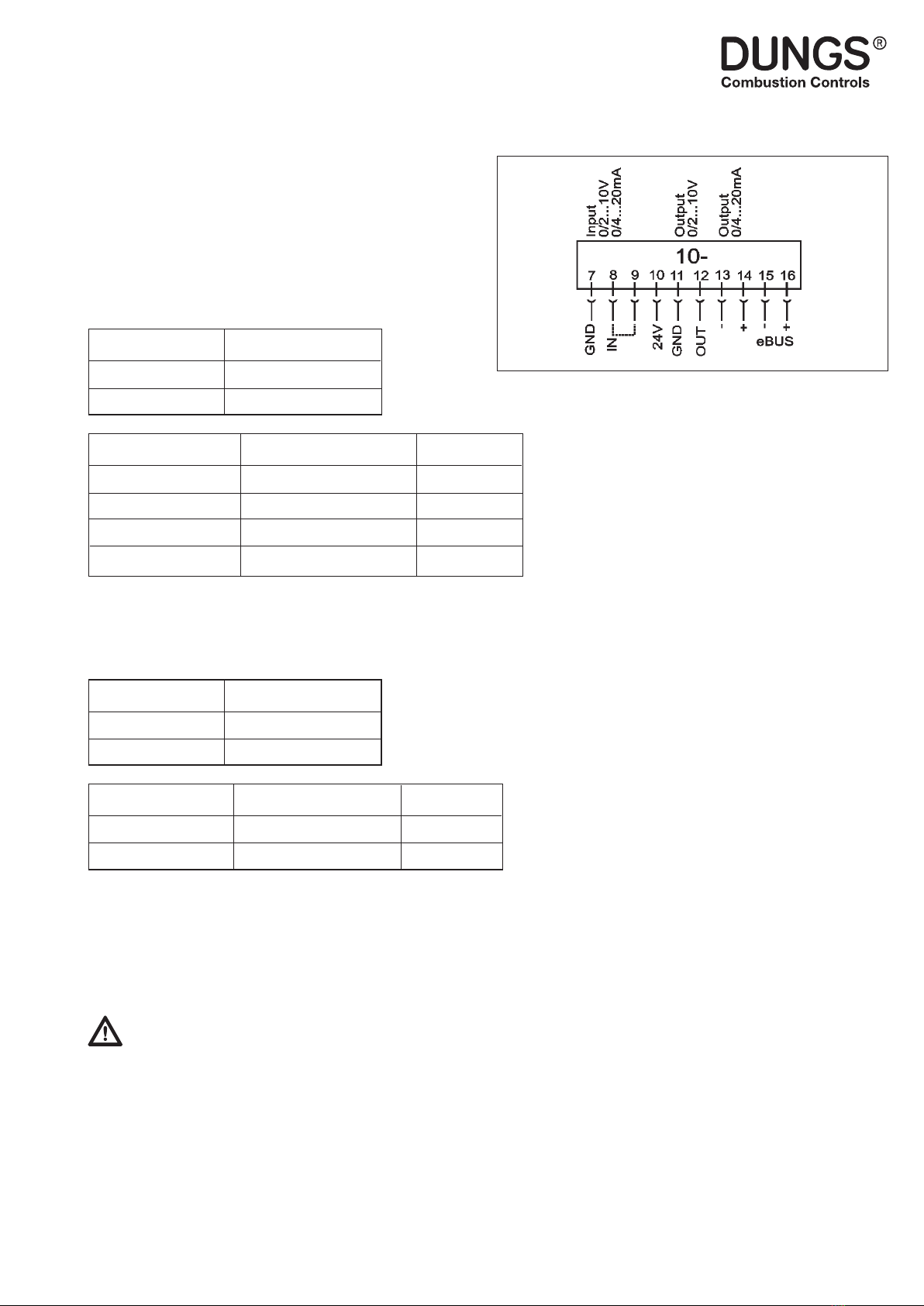
Voltage/current input
Input for controlling the modulation of a
connected MPA series automatic bur-
ner control system using eBUS.
The voltage input converts the 0...10 V
voltage to a modulation depth of 0...100
% and sends this via the eBUS to a
connected automatic burner control
system. The voltage input can be used
as a current input by placing a jumper
between terminals 8 and 9. This current
input can be switched from 0..20 mA
to 4...20 mA using a software switch.
Negligible changes to the input para-
meter are not transmitted immediately.
Changes which are smaller than the
hysteresis
(+/- 5 % of the end value) are transmit-
ted after one minute.
Voltage/current input
The DLU 02 supplies the modulation
depth sent by the MPA as an analogue
output variable. A modulation depth
of 100 % (10 V) means 100 % power
whereas a modulation depth of 0 % (0 V)
indicates that burner is running at mini-
mum power. The modulation depth can
be measured as a current signal (0...20
mA) using the current output. This out-
put can be adjusted to 4...20 mA using
a software switch. As the output signals
of the voltage and current outputs are
internally linked, the voltage output also
switches from 0...10 V to 2...10 V.
Power supply output
There is a power supply of 24 VDC for
powering external modules (such as
level converters). This supply has a load
capacity of max. 25 mA.
eBUS interface
The DLU 02 has a fully-functional
eBUS interface. An eBUS supply with
a constant current of 20 mA and SYN
character generator are integrated.
0 %
50 %
100 %
Modulation depth
0 V
0/4 mA
5 V
0/4 mA
10 V
0/4 mA
Input
Hysteresis
“Four-wire eBUS” connection
To connect the DLU 02 to automatic
burner control systems which are only
equipped with a “four-wire eBUS”
interface (e.g. MPA22), the DLU 02
is also tted with such an interface.
Both devices can be interconnected
using a special connecting cable
without the need for a special MPA/
eBUS adapter.
Connection for external display
unit
The DLU 02 is parameterised using
an external display unit which is not
required for operation. The display unit
is a special accessory.
Alternatively, you have the option
of parameterising the DLU02 with
MPA-Vision.
DLU 02
power
converter
PC with
MPA-Vision MV5
eBUS
PC adapter
Automatic
burner control
system
eBUS
Regulator
Analogue control variable
0...10 V, 0...20 mA
or 4...20 mA
Analogue return signal
0...10 V, 0...20 mA
or 4...20 mA
Display
Mains
Other eBUS-
subscriber