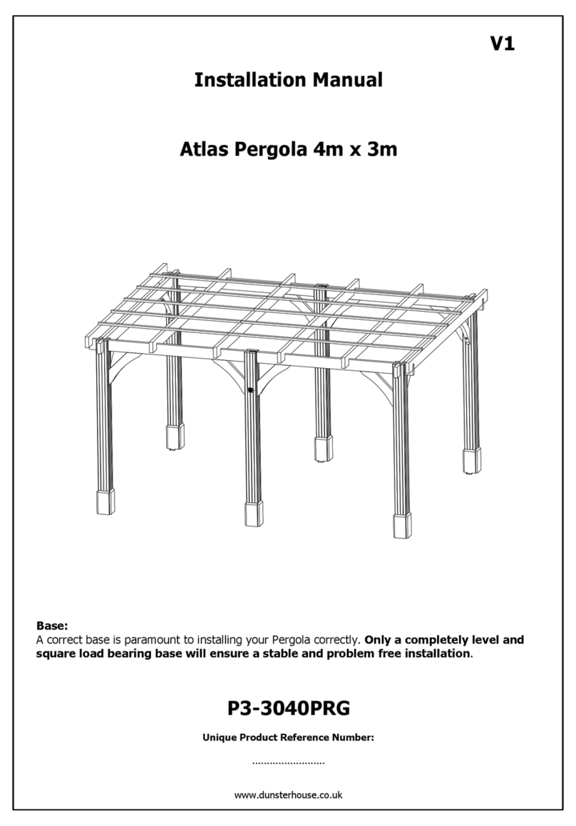
Dunster House H4-GS3X3MK2PRG User manual

Installation Manual
For
Utopia Pergola 3m x 3m
H4-GS3X3MK2PRG
Unique product reference number
.........................................................................
www.dunsterhouse.co.uk
V1

Page 2
Components required for Utopia Pergola 3m x 3m
1965
70x70x1965
4x Pressure Treated Post
70
70
70x35x350.C
8x Pressure Treated Post Fascia
70x35x650.C
8x Pressure Treated Brace
86x43x3000
2x Pressure Treated Beam
30x20x3300
5x Pressure Treated Trim
86x43x3300
2x Pressure Treated Beam
86x43x3300.N
5x Pressure Treated Beam
70
350
35
3300 20
30
3300 43
86
650
35
3000 43
86
3300 43
86
70
Accessories
DESCRIPTION QTY
50mm Screws 25
70mm Screws 66
95mm Screws 8

Page 3
Utopia Pergola 3m x 3m Installation Manual
Step 1
Components required:
Post - 70x70x1965 (4 required)
Beam - 86x43x3000 (2 required)
Beam - 86x43x3300 (2 required)
70mm Screws (16 required)
Please remember to pre-drill all holes before fixing, to avoid the splitting of timber.
Fix the components 86x43x3000 and 86x43x3300 in the positions shown using 2x 70mm screws per end.
We recommend to secure the Pergola legs to the ground using metal brackets, metal connectors etc. (not supplied).
2860
Posts and Beams Layout
Ensure that the diagonals A & B are equal.
Please note that this layout is to assist you with step 2.
Secure using 2x 70mm
screws per end.
2860
70x70x1965
70x70x1965
70x70x1965
86x43x3000
86x43x3300
86x43x3000
86x43x3300
3086
3000
3000
A
B
3300
107

Utopia Pergola 3m x 3m Installation Manual
Page 4
Step 2
Components required:
Brace - 70x35x650.C (8 required)
70mm Screws (24 required)
95mm Screws (8 required)
Once the frame is assembled, fix the
braces 70x35x650.C in the positions
shown using 3x 70mm screws and
1x 95mm screw per brace.
70mm Screws
95mm Screw
70mm Screw
70x35x650.C
70x35x650.C
70x35x650.C
70x35x650.C

Utopia Pergola 3m x 3m Installation Manual
Page 5
Step 3
Components required:
Beam - 86x43x3300.N (5 required)
70mm Screws (10 required)
Please note that these
dimensions are approximate.
Flush on all
4 corners
Fix 5x 86x43x3300.N beams using 1x 70mm screw at
either end of the beam. Ensure that the beams are evenly
spaced, as shown in the diagram below.
822 721 721 822
Flush
70mm
Screw
715 715
86x43x3300.N
86x43x3300.N
86x43x3300.N

Utopia Pergola 3m x 3m Installation Manual
Page 6
Step 4
Components required:
Trim - 30x20x3300 (5 required)
50mm Screws (25 required)
Please note that these
dimensions are approximate.
Once the main beams are in place, you are ready to fix 5x
30x20x3300 trims on top of the beams. Place the trims in
the opposite direction to the beams, with an even spacing,
as shown in the diagram.
Fix the trims using 5x 50mm screws per trim.
625
475
475
475
475
625
50mm Screw
30
20
50mm Screw
30x20x3300
30x20x3300

Utopia Pergola 3m x 3m Installation Manual
Page 7
Step 5
Components required:
Post Fascia - 70x35x350.C (8 required)
70mm Screws (16 required)
On the base of the posts, fix 2x 70x35x350.C to each post on the outside of the Pergola. The angled end of this component
needs to be pointing upwards. Use 2x 70mm screws per component to fix into position.
2x required
2x required
2x required
2x required
2x 70mm screws per post fascia
70x35x350.C
70x35x350.C 70x35x350.C
70x35x350.C

Installation Manual
For
Utopia Pergola
(Additional Wall Panel Pack)
Unique product reference number
.........................................................................
http://www.dunsterhouse.co.uk
Dunster House Ltd.

Page 9
Utopia Pergola 3m x 3m - Pack may contain
2m Solid Wall Panel
Pressure Treated
Solid Wall Panel
3m
Pressure Treated
Pressure Treated
Glass Wall Panel
LOOSE COMPONENTS
2m
2x
2x
Horizontal Beading Timber - Per Window
Pressure Treated
Vertical Beading Timber - Per Window
Pressure Treated
850850
701860
1860 70
850
702860
877
741
19
19
19
19

ACCESSORIES
QTYPART NUMBER
Varies
70mm Screw For Panels
Varies
40mm Pin Nail For Beading Trims
Page 10
Utopia Pergola 3m x 3m - Pack may contain
Pressure Treated
Glass Wall Panel
LOOSE COMPONENTS
3m
2x
2x
Horizontal Beading Trim - Per Window
Pressure Treated
Vertical Beading Trim - Per Window
Pressure Treated
70
2860
850
19
19
905
19
19
741

Page 11
Utopia Pergola 3m x 3m - Additional Panel Assembly
All dimensions are approximate and subject to the limitations of the material used and the methods of manufacture
Full Height Wall Panel Assembly
•Position the solid wall panels between posts as shown in the diagram below.
•Connect panels to posts using 6x Screws. (Repeat this process dependant on how many panels have been
purchased).
•Position a further set of panels directly above previously secured panels and connect using 2x Screws as
shown in the diagram below. (Repeat this process dependant on how many Panels have been purchased).
•Connect panels to posts using 6x screws.
•Use Sealant to seal any gaps which might appear between the panel and the posts.
•3m Solid Wall Panel
•2m Solid Wall Panel
•70mm Screws
70mm Screw
70mm Screw
70mm Screw
**Quantity of components will vary, depending on your purchase

Page 12
Utopia Pergola 3m x 3m - Additional Panel Assembly
All dimensions are approximate and subject to the limitations of the material used and the methods of manufacture
Half Height Wall Panel Assembly
•See Previous page for Solid Wall Panel Installation.
Glass Wall Panel Assembly
SKIP STEP IF CUSTOMER HAS NOT PURCHASED ADDITIONAL GLASS WALL PANELS
•Position Glass Wall Panels directly above previously secured Solid Wall Panels and connect using 2x screws as shown
in the diagram below. (Repeat this process dependant on how many Glass Wall Panels have been purchased).
•Connect Glass Wall Panels to posts using 6x Screw.
•Use Sealant to seal any gaps which might appear between the panel and the posts.
•3m Solid Wall Panel
•3m Glass Wall Panel
•2m Solid Wall Panel
•2m Glass Wall Panel
•70mm Screws
70mm Screw 70mm Screw
**Quantity of components will vary,
depending on your purchase

Page 13
Principle of Glass Installation
Step 1: Place silicone around the edge of the frame.
1x - Glass
16x - Pin Nail
2x - Horizontal Beading Trim
2x - Vertical Beading Trim
Step 2: Place the GLASS into panel frame and make sure it is centralised.
Once Glass is in place apply silicone around the glass to secure it into place.
Step 3: Pre-drill the holes for the pin nails into the glass beading timbers.
Step 4: Fix beading ensuring it is parallel with their counterparts and secure using 40mm pin nails as shown in the image
below.
Please note:
The glass is a smaller size compared to panel
frame to compensate for timbers contracting,
swelling and glass not being cut square.
Silicone
Silicone
Silicone Silicone
Silicone
Silicone
Silicone
Silicone
Please Note: This diagram represents how to install one window panel frame. Please apply this procedure to all window
frames purchased.
**Quantity of components will vary, depending on your purchase
40mm Pin Nail For Beading Trims40mm Pin Nail For Beading Trims
Other Dunster House Lawn And Garden Equipment manuals
Popular Lawn And Garden Equipment manuals by other brands

Garten Meister
Garten Meister GMXB1020-2 Original instructions

Earth Way
Earth Way 2030P-Plus Assembly and operating instructions

Gardeners
Gardeners 8598238 quick start guide

FLORABEST
FLORABEST 79822 operating instructions

Z.I.P.P.ER MASCHINEN
Z.I.P.P.ER MASCHINEN ZI-GPS182J user manual

Yard Works
Yard Works LSS020-1 owner's manual