Durabilt DFSOC-10 Instruction manual

Dura-Fold Slide Out Cover
Assembly and Installation Instructions
Dura-Bilt Products, Inc. P.O. Box 188 Wellsburg, N.Y. 14894
DURA-BILT RESERVES THE RIGHT TO CHANGE DESIGN AND/OR SPECIFICATIONS WITHOUT NOTICE.
Check the material received.
Match your shipment with the Bill of Materials.
If there is a shortage or wrong material,
call Dealer Service immediately.
Safety is important!
Wear Safety Glasses and Work Gloves.
Follow all safety practices while assembling
and installing this product.
DFSOC-10
Read the instructions before starting the job. They explain the steps required
to produce a finished product that will meet factory specifications.
All references to “Left” and “Right” are while facing the home.

Page 1
Fasteners Description
#8 x 1/2” Self Drilling Screw
#8 x 3/8” SS EPDM Washer
#12 x 3/4” Self Drilling Screw
#12 x 1-1/2” Hex Screw
1/4”-20 x 2” Hex Aluminum Bolt
#10-24 Aluminum Wing Nut
1/4”-20 Aluminum Wing Nut
#10-24 x 1/2” Thumb Screw
1” OD x 9/32” ID SS Fender Washer
1/4”Quick Release Pin
1-1/2” OD x 1/4” ID White Bonded EPDM Washer
Note: The Dura-Fold Slide Out Cover is NOT made to travel down the road!
It must be removed for travel.

Page 2Sealer Tape (Peel & Seal) Caulk
Component Descriptions
“U” Channel Panel Hinge Mounting Rail
Front, Left & Right Trim 1-1/2” x 2-1/2” Header Angle End Cap (Right Side)
Left Side Opposite
Lock Down Bracket Correctly Oriented RV Rail
(If Required) Slide Out Roof Panel
“H” Bar
Tools Needed
Screw Gun Caulk Gun Level 3/16”, 7/32” & 1/4” Drill Bits Tape Measure
Lubricant (Furniture Polish) Marking Instrument 1/4”, 5/16” & 7/16” Nut Driver Bits with Magnetic Heads
Hardware Provided
Important!
Because there is no way to know
theconfigurationof every RV Slide
Out it will be necessary for the in-
staller to select the proper fastener
for the HeaderAngle installation to
the RV Slide Out.
(Use a minimun #12 fastener)

Getting Started
Note: this product is sold in widths of 4’increments and will be as-
sembled in the field from the supplied components.
1. Preparing RV Rail for Mounting Rail.
A. If the RV does not have a factory installed RV Rail or RV Rail is badly damaged, it is necessary to install a
new one where you are going to install the Slide Out Cover. Install the RV Rail above the slide out as far as
you can. Dura-Bilt supplies RV Rail with every Slide Out Cover that has the correctly oriented opening for
the Mounting Rail. Caulk the back side of the RV Rail and install #12 x 1-1/2” Hex Screws in every hole.
B. If the RV has RV Rail make sure the RV Rail is clear of dirt and debris , it may be necessary to loosen the
fasteners along the RV Rail; this will allow you to slide the Mounting Rail on easier. Leave fasteners loose
until instructed to tighten.
2. References made to the left and right ends of the Slide Out Cover are determined when viewed facing the
RV.
3. Because there are various styles of RV Rails it may be necessary to shim the Mounting Rail. See
drawings above. Shim material is not provided with the Slide Out Cover. Caution! Make sure that when
you have completed this step that the Mounting Rail is below horizontal or water will run back to RV wall and
cause leaking.
Page 3
Note: If you must shim the Mounting Rail, you should replace the #12 x 1-1/2” screws provided with
new screws of an appropriately longer length.
Shim

Mounting Rail Installation
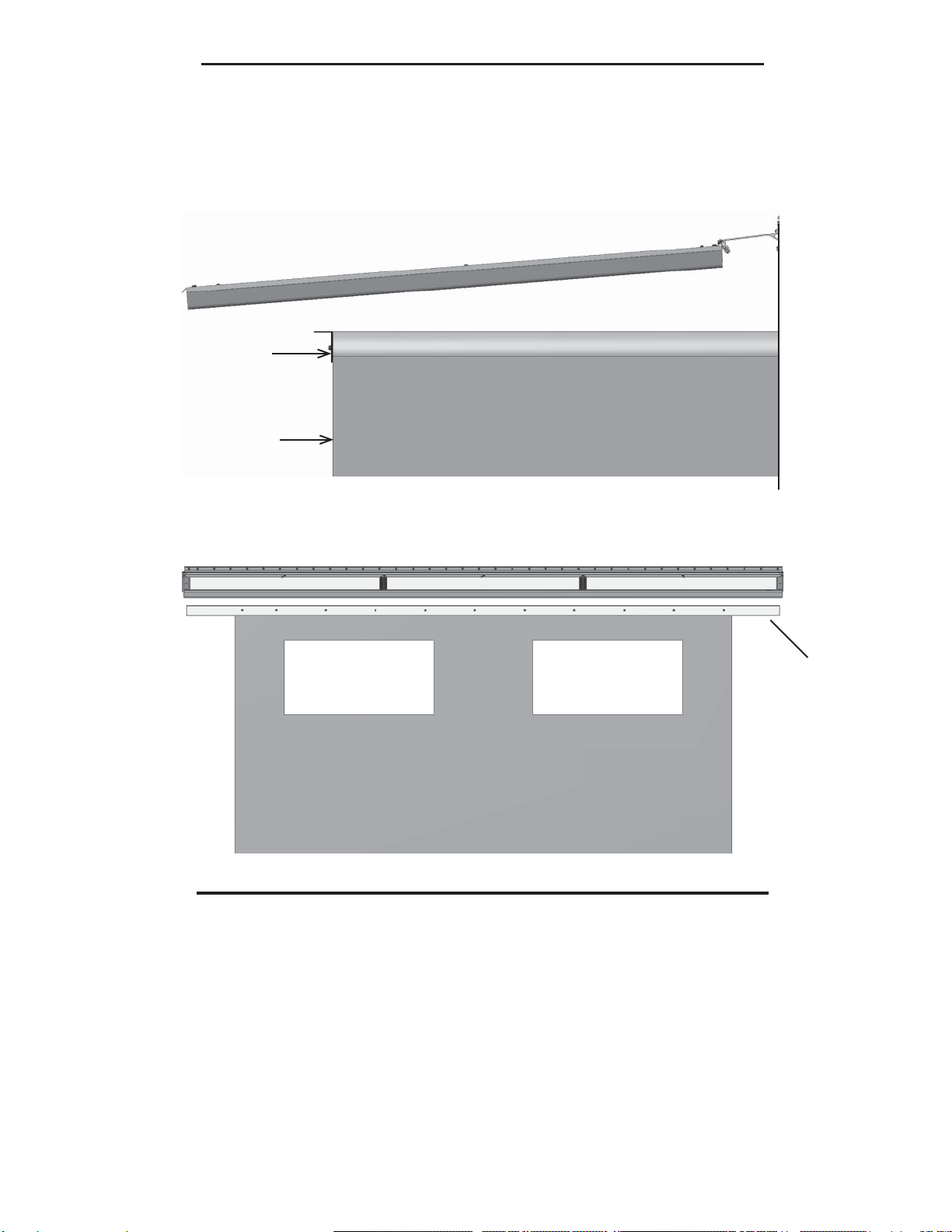
Note: The RV Rail may be slightly shorter than the Mounting Rail.
Note: this product is sold in maximum section widths of 4’and will be assembled in the field from the
supplied components. If it’s necessary to shorten the Slide Out Cover any or all panels can be cut, and
extrusions shortened. Front Trim should be shortened at the joint, not at left or right end, due to
factory machining.
1. Determine where the Slide Out Cover is to be positioned along the RV Rail and mark that location on the
RV Rail.
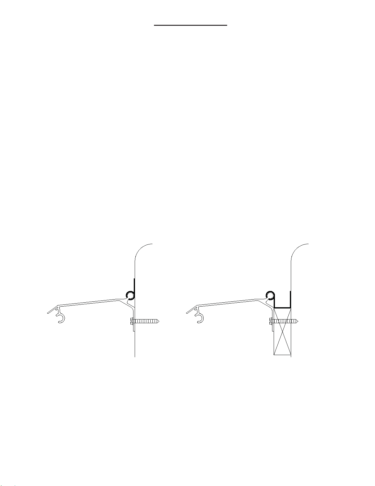
2. Before sliding the Mounting Rail into the RV rail, spray the RV rail cavity with a lubricant such as furniture
polish.
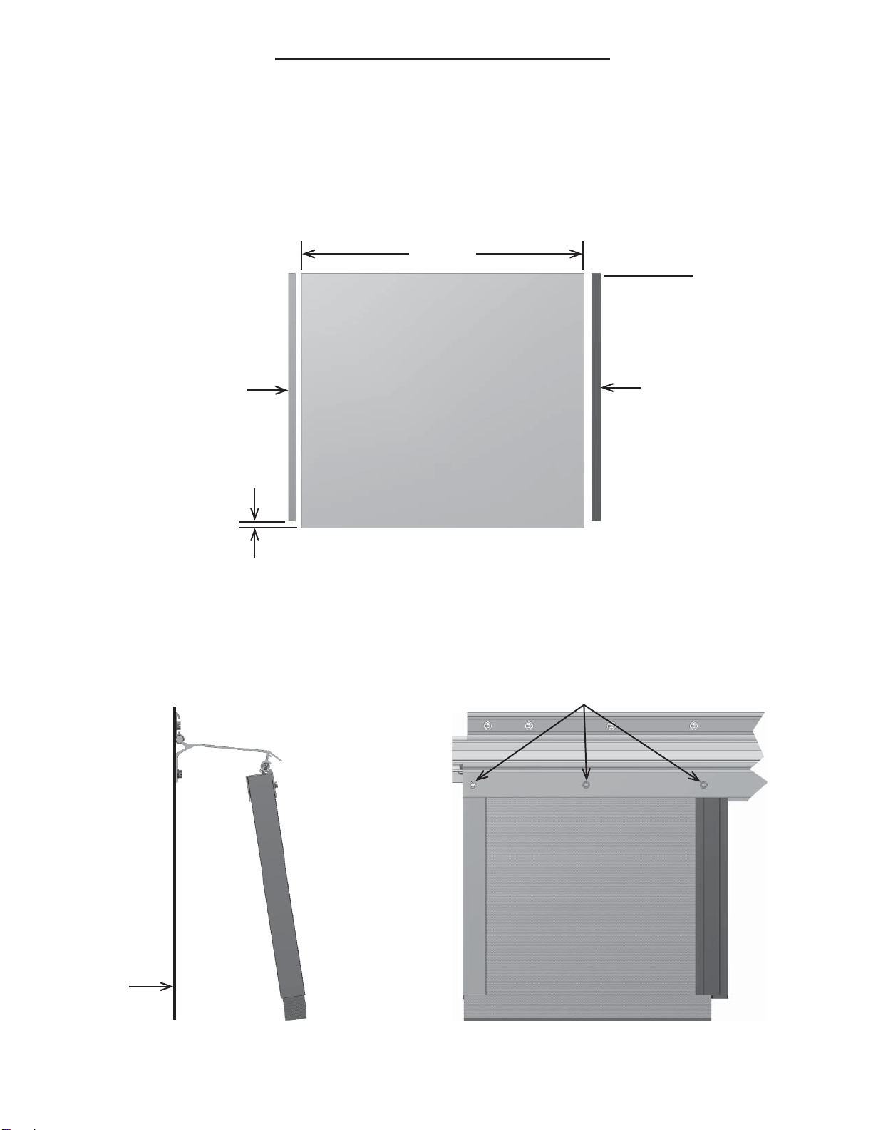
3. Slide the Left End Mounting Rail section into the RV Rail until
it reaches the mark made previously.
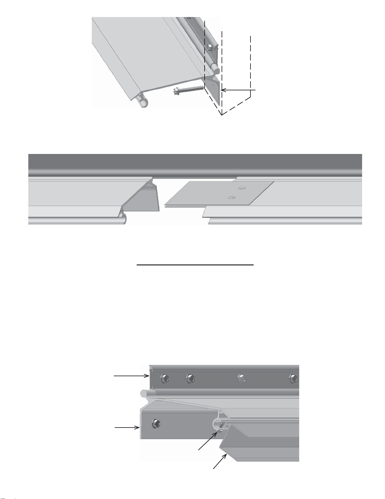
4. Mark the locations of all RV studs or solid support
(normally 16” on center) on the bottom leg of the Mounting
Rail. Drill 7/32” holes through the Mounting Rail at the
locations you marked.
5. Apply caulk to the back side of the Mounting Rail bottom
leg before attaching with screws.
Page 4
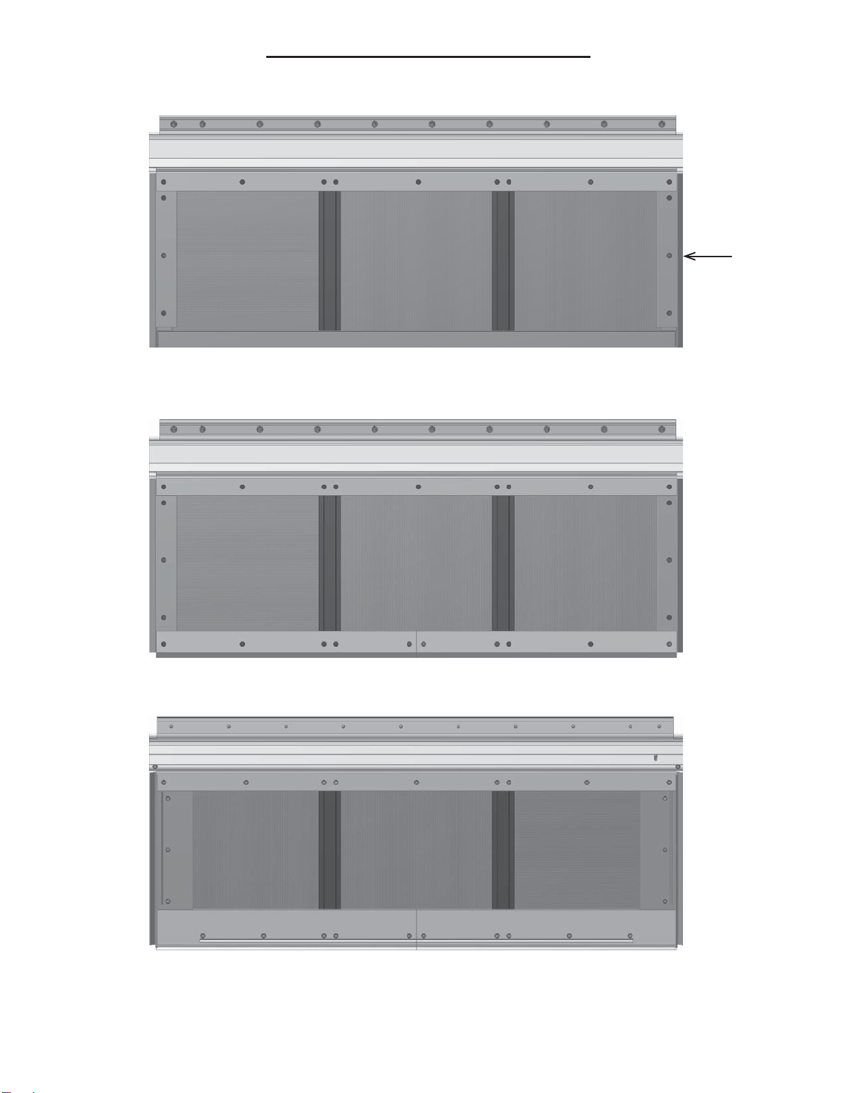
6. Attach Mounting Rail to the RV with a #12 x 1-1/2” Hex Screw to keep the Mounting Rail from moving
when the Panel Hinge is installed.
7. Using the same procedure, install any remaining sections of Mounting Rail.
8. Install the #12 x 1-1/2” Hex Screws in the remaining holes that you previously drilled.
RV Rail
Mounting Rail
Mounting Rail

9. If you loosened any fasteners in the RV Rail, tighten them now. First, apply a generous bead of caulking
in the cavity between the RV Rail and the side wall of the RV. Also caulk full length of top of the joint of
Dura-Fold Mounting Rail and the RV Rail.
Page 5
Panel Hinge Installation
1. Before sliding the Panel Hinge into the Mounting Rail, spray the Mounting Rail cavity with a lubricant
such as furniture polish.
2. The Mounting Rail is an inch longer than the Panel Hinge. Install a #8 x 1/2” screw thru the left end of the
Mounting Rail so the Panel Hinge will stop a 1/2” from the end.
3. Slide your Panel Hinge section(s) into the Mounting Rail, starting on the right and sliding to the left to the
stop. When all sections are installed, Install a #8 x 1/2” screw thru the right end of the Mounting Rail so the
Panel Hinge will stop a 1/2” from the end.
Mounting Rail
Stud
Mounting Rail
Bottom Leg
RV Rail
Mounting Rail
#8 x 1/2” Screw
Panel Hinge
Note: If you are installing more than one section of Mounting Rail, as you slide each Mounting Rail section
into position, make sure legs of the Mounting Rail Joiner straddle the rail already in place.
Mounting Rail
Joiner Mounting Rail

Page 6
Panel and Extrusion Assembly
1. Start by sub-assembling the left panel on the ground.
2. Install a “U” Channel on the left side of the Panel and an “H” Bar on the right side of the Panel. Make sure
the assembly is together tight.
Note: The “U” Channel and “H” Bar are shorter than the Slide Out Roof Panel. The flush side fits into
the Panel Hinge. Maximum panel section width is 48”, the projection is based on the RV Slide Out.
Slide Out Roof Panel
“U” Channel “H” Bar
Max. 48” Flush
1-1/8”
3. Starting at the left, insert the subassembly into the Panel Hinge. Make sure the subassembly is fully insert-
ed into the Panel Hinge and flush with the left side.
4. Install three (3) #8 x 1/2” screws thru the Panel Hinge. One thru the Panel Hinge and into the “U” Channel
on the left side. One in the center of the panel thru the Panel Hinge and into the Panel. One thru the Panel
Hinge lined up with the left screw groove in the “H” Bar.
Continued on next page.
Side of RV
Mounting Rail
Side View
#8 x 1/2” Screws
“H” Bar“U” Channel
Slide Out Roof Panel

Page 7
Panel and Extrusion Assembly
5. Install the next panel, making sure it is tightly together before installing the next three (3) #8 x 1/2” screws
as you did in step 4 on the previous page. Install the rest of the panels in the same maner and install a “U”
Channel over the right side of the last panel, then install the next three (3) #8 x 1/2” screws.
6. Install “U” Channel over the front of all Slide Out Roof Panels. (Do not use any fasteners at this time)
“U” Channel
7. Install Left Trim using three (3) #8 x 1/2” screws. (Make sure the screws go thru the Trim, “U” Channel
and Slide Out Roof Panel)
Continued on next page.
“U” Channel “U” Channel
“H” Bar “H” Bar
Left Trim

Page 8
Panel and Extrusion Assembly
8. Install Right Trim using three (3) #8 x 1/2” screws.
9. Install the Left & Right Front Trims using #8 x 1/2” screws in the pattern shown in illustration below.
10. Hold the Slide Out Cover up and install #8 x 1/2” screws in the pattern as shown in illustration below.
Top view of Slide Out Cover
Bottom view of Slide Out Cover
Right Trim

Page 9
Front View of Slide Out and Slide Out Cover
Header Angle
v
3. Pre-Drill the Header Angle and install the fasteners in an appropriate amount from each edge and then
every 12” as shown in the Front View illustration below.
1. Lower the Slide Out Cover down to the Header Angle and determine the location of the 1/4”-20 x 2” aluminum hex
head bolts and 1-1/2” dia. washers.
2. Use a chalk line to mark the horizontal location of the bolts.
3. Mark the vertical location of three (3) bolts per panel for attachment thru the Header Angle. Use a 1/4” drill bit and
drill your first hole and install the bolt with 1-1/2” washer thru the Slide Out Cover and Header Angle.
4. Install 1” Fender Washer and 1/4”-20 Wing Nut to keep the Slide Out Cover from moving.
5. Drill for and install the remaining fasteners as per illustration(s) on next page.
Installation of the 1-1/2” x 2-1/2” HeaderAngle
Attachment of Slide Out Cover to HeaderAngle
Side View of Slide Out and Slide Out Cover
Header Angle
Slide Out Face
1. Hold the Slide Out Cover up and extend the RV Slide Out. Locate and mark where the Header Angle is to be attached
to the face of the RV Slide Out. The Header Angle should be flush with the top of the Slide Out and fit between the two
(2) Valance legs of the Slide Out Cover.
2. Because there is no way to know the configuration of every RV Slide Out it will be necessary for the installer to select
the proper fastener for the Header Angle installation to the RV Slide Out. (Use a minimun #12 fastener)

Page 10
1/4”-20 x 2”
Hex Bolt
with
1-1/2” Washer
Attachment of Slide Out Cover to HeaderAngle (continued)
Sealing all Seams
You are supplied with Sealer Tape (Peel & Seal) to cover the seams in the Mounting Rail, Panel Hinge and
Front Trim. Measure and cut the lengths needed, remove film covering the black, sticky surface and apply
over all seams. Make sure that Sealer Tape (Peel & Seal) adheres to all surfaces.
Top View of Slide Out Cover
Caulking Slide Out Cover
Caulk all seams on top of the Slide Out Cover as shown by the dotted lines in the illustration below.
Side View of Slide Out Cover
Caulk Around 1/4” Hex Bolt

Install Flashing
You will receive a strip or strips of Flashing (depending on the length of your Slide Out Cover) that are to
be inserted into the flashing recess on the Mounting Rail. The Flashing comes in 10’lengths. They are
overlapped by a minimum of 1”. #8 x 1/2” screws with #8 x 3/8” SS EPDM Washers are used to attach
Flashing to the Mounting Rail. Depending on the pitch of the Slide Out Cover you may not be able to use the
flashing, so just caulk.
Off Season Storage
The Dura-Fold Slide Out Cover can be folded down as a complete unit.
Important: Remove all wing nuts and fender washers and raise the Slide Out Cover away from the
HeaderAngle. The Header Angle may remain attached to the RV Slide Out permanently. Retract the
RV Slide Out into RV and lower Slide Out Cover. Replace the washers and wing nuts on the Slide Out
Cover bolts for storage.
Note: You will receive four (4) Lock Down Brackets with your order. Two (2) required for each side.
1. Locate a substantial framing member on the RV to attach the Lock Down Bracket. The Lock Down
Bracket that is attached to the Front Trim must line up with the Lock Down Bracket that is attached to the RV.
2. Attach Lock Down Bracket to the RV with two (2) #12 x 1-1/2” screws.
3. Attach Lock Down Bracket to the Front Trim of the Slide Out Cover with two (2) #12 x 3/4” screws.
4. After the two (2) brackets are installed; use a 1/4” drill bit to drill thru all four (4) legs and install the 1/4”
Quick release Pin. See illustrations on next page.
Page 11
Note: The Dura-Fold Slide Out Cover is NOT made to travel down the road! It must be
removed for travel.
Note: If you are going to leave your Slide Out Cover up through the winter, you should
consider placing support under the RV Slide Out.
Flashing
#8 x 1/2” screws &
#8 x 3/8” SS EPDM Washers
Side View of Flashing Installation

Install Valance Trim
1. You may start the Trim Valance at either front corner.
2. Feed the vinyl bead edge of the Trim Valance along the Valance Track of the Front Support until you reach
the other corner. Adjust Valance so that you have an equal amount of Valance remaining at each corner.
Hint: The Valance will slide more easily if one person pulls the leading end of the Valance along the Track
while another feeds it into the Track.
3. Feed the Valance Bead along the Valance Track on both Side Trims to the wall of the RV.
4. Trim the end of the valance so it will butt against the RV wall. You should
use a “hot knife” or heat the cut end so the material won’t fray.
Install Mounting Rail End Caps
Attach End Caps to both ends of Mounting Rail with 1/2” Thumb Screw and
Wing Nut. You will need a 3/16” drill bit to pre-drill hole.
Side View of
Slide Out Cover folded down
showing Lock Down Bracket
installation.
Off Season Storage (continued)
End Cap
Page 12
Note: the views of the Lock Down Bracket below are shown for clarity but for ease of assembly rotate
90 degrees.
Side View of
Slide Out Cover folded down.

Notes
Page 13

Notes
Page 14

DURA-BILT PRODUCTS, INC.
Five Year Limited Warranty
Dura-Bilt Products, Inc. warrants its manufactured products to the original
purchaser to be free from defects in materials or workmanship under the terms and
conditions set forth herein. All other components and parts carry their own
manufacturers warranties.
Within the warranty period, to be confirmed with copy dated bill of sale,
Dura-Bilt Products, Inc. will, at its sole option, repair or replace any components
which the owner has proven to have failed in normal use. Such repairs or
replacement will be made, at no charge for parts, to the original purchaser.
Provided, however, that the original purchaser shall be responsible
for any transportation or freight costs. Replacement of materials does not extend
original warranty period. This warranty does not include the cost of labor for
installation of parts.
Continuing product developments require that Dura-Bilt Products, Inc.
retain the right to substitute replacement parts or components of equal quality, if
necessary. Normal aging and weathering of materials may result in not being able
to perfectly match the original colors.
This limited warranty does not cover failures due to weather, acts of God,
abuse, misuse, improper installation, accident, alteration or repair. Dura-Bilt
Products, Inc. assumes no responsibility for special, incidental, punitive or
consequential damages or loss of use.
THIS LIMITED WARRANTY IS EXCLUSIVE AND IN LIEU OF
ALL OTHER WARRANTIESAND REMEDIES EXPRESS OR IMPLIED,
INCLUDING ANY LIABILITYARISING UNDER THE WARRANTY OF
MERCHANTABILITY OR FITNESS FOR A PARTICULAR PURPOSE,
STATUTORY OR OTHERWISE. THIS WARRANTY GIVES YOU
SPECIFICALLY THESE RIGHTS WHICH MAY VARY BY STATE.
This warranty covers products manufactured by Dura-Bilt after 9/1/95.
To obtain warranty service, call the Dura-Bilt Products Customer Service Department at
1-570-596-2000 or write to P.O. Box 188, Wellsburg, NY 14894-0188. Retain this Warranty for
your records.
Page 15
Table of contents