Durite 0-870-20 User manual

0-870-20 360° Monitoring System
With Control Box

CAUTION........................................................................... 01
SUMMARY.........................................................................01
SYSTEM COMPONENTS .....................................................02
CONNECTION OF THE WHOLE SYSTEM..............................03
PARAMETERS ADJUSTMENT CONTROLLER ........................03
CALIBRATION ....................................................................04-15
CLEANNING AND CARING ................................................. 15
SPECIFICATION..................................................................15-16

WARNING:
The 360° monitoring system is to be used as an auxiliary safety device. The vehicle operator
should be aware of his surrounding at all times! Please ensure you are familiar and comply
with local traffic and driving regulations.
CAUTION
Power
1. Supply DC 12/24V. Please check voltage before installing.
2. Please disconnect the power supply if not in use for a long period of time.
Safety
1.This ECU is design for indoor usage. To prevent from short circuit or being
shocked, please keep machine away from humid environments.
2.If any liquid or solid materials enter the machine, cut off the power
immediately. Please ask professional technicians to examine the unit before
it can be used again.
3.If any fault occurs, please ask a professional technician to examine or
contact your local distributor.
Installation location
1.Please install in a ventilated location to prevent the machine from overheating.
2.Keep the machine away from the radiator and exhaust area, or downpour, dust,
humidity, strong magnetic fields and places that will cause vibration or shock to
the machine.
Copyrighted
1.While recording please ensure you are familiar and comply with local traffic and
driving regulations.
2.Without approval from our company, any refit or adjustment will void warranty.
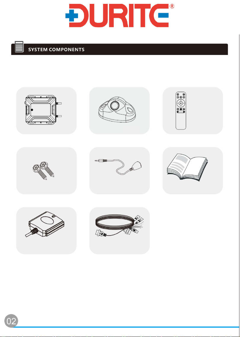
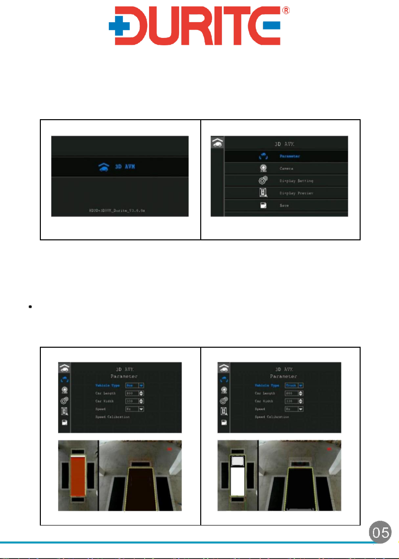
The around view monitoring system provides high resolution images, which are captured from four
AHD camera's installed around the vehicle. It combines the surrounding images of the vehicle into
a vehicle virtual 360° birds eye view image. The system assists the operator to visually identify
obstacles in all directions of vehicle, it covers the blind - spots where accidents often happen. The
innovative 360° monitoring system simplifies the installation. All that is required are fixed dimension
mats, a small area and your vehicle dimensions to be input into the control box, the unit can auto
calibrate and will provide a 360° birds eye view image based on the values input.

Please unpack the package and check whether you have received the
following items.
Control Box
Screws IR Manual
GPS Module
Y-Cable
02
Remote Control
0-870-98 Camera

Before making the connection disconnect the ground terminal of the
vehicle battery to avoid short circuiting the system.
Please make sure all connectors or jacks are inserted correctly to ensure system
stability.
1. REMOTE CONTROLLER BUTTONS
0-870-98 Camera
0-870-98 Camera
0-870-98 Camera
0-870-98 Camera
Durite Monitor
IR
Power
Emergency recording
Rewind video
Pause video
Fast forward video
Up/Down
Left/Right
Confirm
Return
AVM Screen display
Save
AVM menu
DVR menu

2. CALIBRATION
2.1 Prepare work
a. Before setting, make sure you have got following calibration mats:
Mat A: 3.1m x 1.3m (figure 2.1-1)
Mat B: 5.6m x 2m (figure 2.1-2)
1.3m
3.1m
2.5m
0.7m
(Figure 2.1-1)
5.6m
5.0m
2.0m
1.4m
(Figure 2.1-2)
2.2. Calibration ground
a. Find a large space for calibration. Drive the vehicle in to the space. Make sure the corner of
vehicle can be seen on the screen.
b. Placement of calibration mats
Different types of vehicles have different length and width, so the placement of mats
is different. The usage conditions and placement methods have the following
restrictions:
Vehicle length is: 3.1m<length<6.0m
use 4x mat A
Vehicle length is 6.1m<length<13m
Use 2x mat A and 2x mat B
04
Mat A
Mat A
Mat A
Mat A
Mat A
Mat A
Mat B
Mat B

2.3. Setting and calibration
After the system is powered on and the around view system screen is displayed, press
the menu button on the remote control to enter the main interface for setting / calibration
(Figure 2.3-1). The software version number is displayed at the bottom. At this point,
press the center button to enter the around view settings menu (Figure 2.3-2).
After entering the menu, use the up, down, left, and right buttons of the remote control to
move the options or adjust the numbers, confirm the setting to enter the next menu.
Return button means to return to the previous menu, when the camera screen or around
view preview image is displayed on the calibration interface. Press the Menu button return
to the menu option.
Parameter setting menu
There are vehicle types, vehicle length, vehicle width, vehicle speed signal type and
vehicle speed frequency correction parameter you need to set.
You can choose bus or truck model to corresponding 3D vehicle model. (Figure 2.3-3
、Figure 2.3-4)
Figure 2.3-3、Bus 3D model
Figure 2.3-4、Truck 3D model
Figure 2.3-1 Setting/Calibration
main interface
Figure 2.3-2 around view settings
menu interface

The setting range of vehicle length is 400~1300cm, The setting range of vehicle
width is 150~500cm (Figure 2.3-5、Figure 2.3-6)
Figure 2.3-5 setting vehicle
Figure 2.3-6 setting vehicle
length parameter
width parameter
Fig. 2.3-7 setting
Fig. 2.3-8 setting Duty Cycle
frequency type
Note 1: During speed calibration, you need to select the vehicle speed calibration option
(Figure 2.3-9). Press the center button, then the system will start to capture the vehicle
speed frequency. When the vehicle is moving at 10 km/hr, confirm the calibration
option. Press the enter button (Figure. 2.3-10) in the calibration option to complete the
vehicle speed frequency correction. After the completion, move to the exit option
(Figure. 2.3-11) and press the enter button to leave the calibration function.
The type of vehicle speed signal can be either frequency type (HZ) (Figure 2.3-7)
or Duty Cycle (Figure 2.3-8), which are determined depending on the type of
speed signal provided by the vehicle. These need to be calibrated. If you cannot
determine the type of speed signal (note 1), you can use the GPS module.

Figure 2.3-9 vehicle speed
Figure 2.3-10 calibrating
calibration
Figure 2.3-11 exit calibration
Camera setting menu
There are camera types, camera installation height, camera position (POS X, POS Y)
parameter you need to set. Image rotation options are temporarily not set. There is
original view option below the interface in which you can check four installed
cameras. Make sure they are all set to CS30J (Figure. 2.3-12).
Figure 2.3-12、setting camera types

The actual value of the camera installation height and camera position POS X and POS
Y (Fig. 2.3-13) (note 2) need to align with the actual installation dimensions of the
camera.
Figure 2.3-13 setting camera installation height and position
Note 2: The camera POS X and POX Y value are shown in Figure 2.3-14.
XY
front front
Y
Y
left
right
The blue box is about 40cm more
than the actual size of the vehicle
Xleft
Xleft
(20cm in front and back, 20cm in left
and right). The length and width of
the blue box need to be set in the
360 system.
Y
Xrear
rear
Figure 2.3-14 parameter of camera POS X and POS Y
08

You can enter the camera preview screen to check actual screen after installing
cameras. During the install of a camera, you need to adjust the elevation angle properly
so that the calibration cloth on the ground is close as possible to the reference line
(Figure 2.3-15~2.3.18), which will achieve the best stitching effect.
Figure 2.3-15 front camera
Figure 2.3-16 rear camera
installation angle
installation angle
Figure 2.3-17 left camera
Figure 2.3-18 right camera
installation angle
installation angle
Display setting menu
The parameter in display setting menu as below:
(1) You can choose whether display screen when moving forward at high speed
(Figure 2.3-19).
Figure 2.3-19 ON/OFF option
09

(2) If you choose display screen when moving forward at high speed, you need to select
picture in picture display or rear camera display (Figure 2.3-20).
Figure 3.3-20 picture in picture display and single display
(3) When high-speed driving requires a left-right turn, the sub-screen of the picture in
picture screen displays the rear camera screen or the 3D model screen (Figure.
2.3-21).
Figure 2.3-21 rear camera display or 3D model display optional
(4) Choose if the screen of the picture in picture displays the static distance line
(Figure 2.3-22) (note 3).
10

Figure 2.3-22 static distance line ON/OFF option
Display Preview menu
Display preview menu including automatic calibration 3D model stitching and
manual point selection 3D model stitching options.
During automatic calibration (Figure 2.3-23), the system will perform image grab
feature points on its own. After the calculation (Figure 2.3-24), you can see the
stitching result of the 3D model and use the left and right buttons to switch ways of
presenting images in difference driving mode (Figure 2.3-25~33).
Figure 2.3-23 automatic calibration
Figure 2.3-24 processing
11

Figure 2.3-25 preview screen 1
Figure 2.3-26 preview screen 2
Figure 2.3-27 preview screen 3
Figure 2.3-28 preview screen 4
Figure 2.3-29 preview screen 5
Figure 2.3-30 preview screen 6
Figure 2.3-31 preview screen 7
Figure 2.3-32 preview screen 8
12

Figure 2.3-33 preview screen 9
If the automatic calibration result is not good, you can use manual calibration method
(Figure 2.3-34) to set the four feature point positions required for the four camera
screens (Figure 2.3-35~39). After finishing the settings if you need to calculate the 3D
model, select this option (Figure 2.3-40). After the calculation is completed, the left and
right buttons can be used to switch the screen rendering modes in different driving
modes.
Figure 2.3-34 manual calibration
Figure 2.3-35 Front camera
four feature points
Figure 2.3-36 Left camera
Figure 2.3-37 right camera
four feature points
four feature points
13

Figure 2.3-38 rear camera
Figure 2.3-39 Zoom in
four feature points
to fine-tune feature
points
Figure 2.3-40 Recalculate
Save menu
The Display Setting menu has four items of parameter storage, parameter export,
parameter import and factory reset (Figure 2.3-41~44). Use the parameter storage
option to save parameter and return to the normal mode screen; Use the parameter
export option to save the parameters to a Micro-SD card; use the parameter import
option to load the parameters from a Micro-SD card. Using the factory reset option,
the above parameters are restored to the original values.
Figure.3-41 save option
Figure 2.3-42 parameter export
14

Figure 2.3-43 parameter import
Figure 2.3-44 factory reset
CLEANNING AND CARING
Caution!
Unplug or power off the system before cleaning.
Do not use sharp or hard objects to clean the device as these may damage the device.
Do not use liquid cleanser or aerosol cleanser.
Clean the device with a soft, damp cloth from time to time.
SPECIFICATION
CONTROL BOX
Rated Voltage
12/24V
Operating Voltage
10~32V
Camera power supply
9V (supplied by the control box)
Power
≤25W(Max. 4 Camera)
Operating temperature
-40℃~+85℃
Storage temperature
-40℃~+85℃
Waterproof &Dust Resistance Grade
IP66
Input image
AHD 720P (NTSC/PAL)
Output image
AHD 720P(NTSC/PAL)/HDMI(TV)
Trigger signal
4 Input / 1 Output
Dimension
170 x 150 x 36(mm)
Weight
960(g)
15

CAMERA
Image type 1/3 CMOS
Resolution (pixels) 1280*720
Color system PAL/ NTSC
Lens angle 180°(H), 127°(V), 190°(D)
Waterproof & Dust Resistance Grade IP68
Power consumption ≤ 2.5W
Signal to noise ratio > 44dB
Dynamic range >80dB
Video signal output 1Vp-p,75ohm
Operating temperature range -30℃to +70℃
Storage temperature range -40℃to +80℃
Dimension 85(L) x 81(W) x 63(D)mm
Weight 300g
15
16
Table of contents
Other Durite Digital Camera manuals