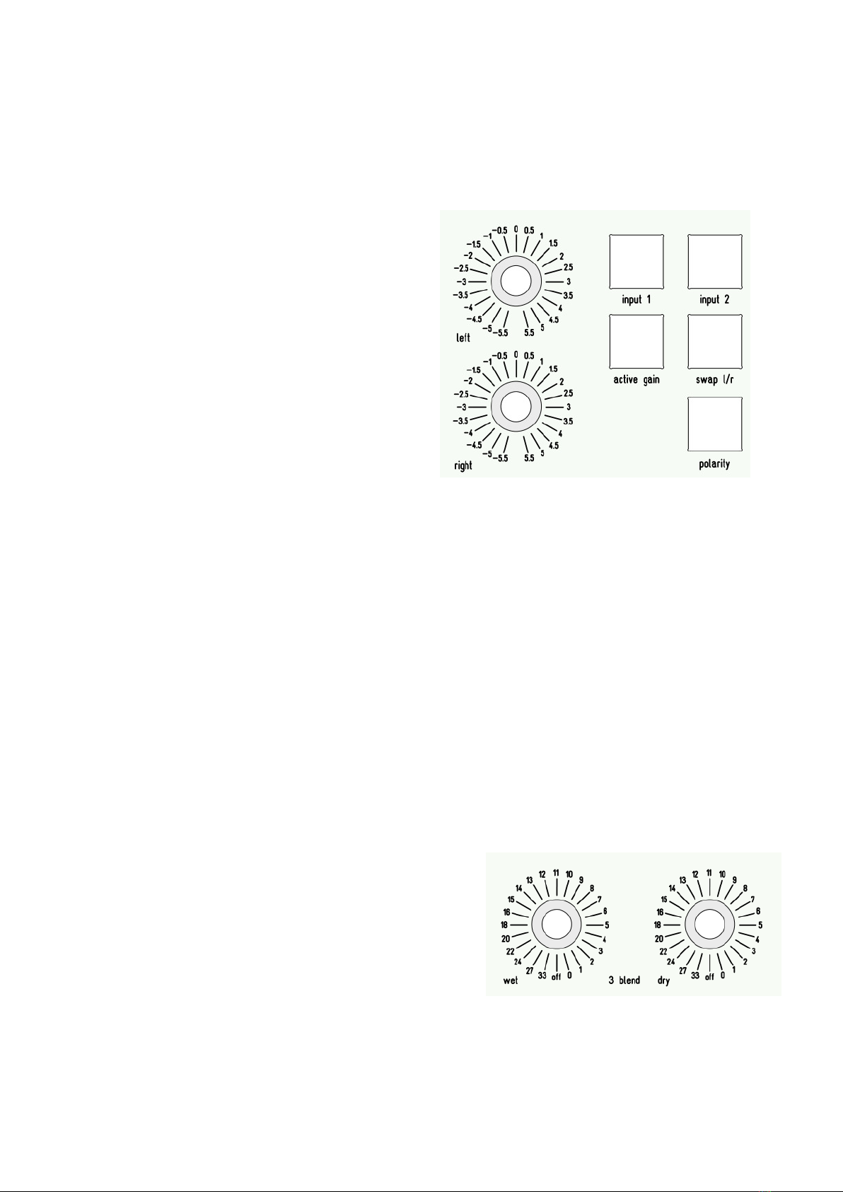
DUTCH IM2.1s User manual

DuTCH audio IM2.1(s) manual

DuTCH audio IM2.1(s) manual
(v1.6 29-06-2021)
Introduction:
Thank you for purchasing the DuTCH audio Insert Machine IM2.1(s). In this manual we will
e plain how this device works and how to use it. Since this is not really a beginner’s device,
we will skip the basics and focus on it’s functions. We will go from the inputs (left side), to
the inserts (middle) and to the outputs (right side), basically how the device handles
signals.
The IM2.1 is available in 2 versions, the IM2.1 and the IM2.1s. The only difference is the
output section. More on this can be found in the output section of this manual.
Important Safety Instructions:
Please follow these precautions when using this product:
Read and keep these instructions.
Heed all warnings and follow all instructions.
Dangerous voltage lives inside this achine. Opening is only allowed by qualified
service personnel.
Unplug this achine during lightning stor s or when unused for long periods of ti e.
Do not use this achine near water or outside.
Clean only with a dry, soft cloth. Do not spray any liquid cleaner onto the cabinet, as
this ay lead to dangerous shocks.
Do not install near any heat sources such as radiators, heat registers, stoves, or other
achines (including a plifiers) that produce heat. Avoid exposure to direct sunlight.
This achine typically runs slightly war when operated. Install in a nor al ventilated
area. If the product will be used in a rack, ake certain there is sufficient air
ove ent within the rack. Preferably offer so e e pty rack space above the unit and
do not place it on top of hot equip ent.
Refer all servicing to qualified service personnel. Servicing is required when the
achine has been da aged in any way, such as when the powersupply plug is
da aged, liquid has been spilled or objects have fallen into the achine, the achine
has been exposed to rain or oisture, does not operate nor ally, or has been dropped.
WARNING: To reduce the risk of fire or electric shock, do not expose this achine to
rain or oisture.

Operation:
Inputs:
Input 1 / input 2:
You can choose between the 2 inputs
by
pushing the corresponding button. It’s
also
possible to use both inputs at the sa e
ti e,
but keep in ind that this could cause
so e
i pedance changes.
Swap L/R:
When you engage the ‘swap l/r’ button the
left
and right channel will be swapped in
order.
So eti es this will bring things to the
surface
that you didn’t notice before because of
the
new listening approach.
Polarity:
The ‘polarity’ button will swap the polarity
of
both Left and Right. So eti es
swapping
polarity will give a better response, ostly in the low frequencies. In ost cases swapping
polarity is not needed, but in the cases where you want to, this button co es in very handy.
Keep in ind that obviously this only works with balanced signals.
Active gain:
Both inputs are passive with just relays, but by pushing the ‘active gain’ button you will
enable the active gain stage which enables you to change the input gain to your liking. In
the id/0 position, there is no gain applied though it passes the active gain circuit. You can
change the gain in 23x0.5dB steps fro +5.5dB to -5.5dB with stepped switches.
Inserts:
Insert 1 and 2:
This is a 100% passive insert section with just relays. When disabled, it will directly pass
the signal internally to the next stage. When you enable the insert (1 and/or 2), it will pass
the signal to the corresponding send/return. It will first pass insert 1 and then it goes into
insert 2. When you push the ‘swap 1 /2’ button, it will swap the order of the inserts. So
instead of 1>2 the order will beco e 2>1.
Insert 3 ( lend):
Insert 3 has an active parallel/blend function.
With
insert 3 you can blend the dry and wet
signal
together. Most parallel processing uses one
control
for blending fro wet to dry and uses a
pot eter.
The IM2.1(s) uses two separate controls for wet
and
dry with stepped switches instead of a
pot eter.
This way you don’t have channel i balance,
easy
recall and way better control over what happens
to
the signal. For instance you can choose to co press the signal and blend in just a bit of dry
signal. But you also choose to use the dry signal and blend in a bit of quite aggressive
co pression. The first steps on the stepped attenuators have 1 dB per step and the last
steps have ore course steps, the lowest step is -33dB. The off position utes the wet or
dry signal.

Blend 3:
With the blend 3 button you can switch between passive or blend/parallel ode.
* note: the first delivered IM2.1’s didn’t have this button.
Using wet/dry as active gain
This is a hidden feature, ‘the Bob Katz mod’. It's possible to activate the blend
function even when insert 3 is not activated. The wet and dry knobs become gain
knobs and they will be behave like an active gain in between the inserts. Because
the wet control is not passing the insert itself, you can combine the wet/dry gains to
add up to 6dB gain.
Insert 4:
Insert 4 is a regular passive insert.
Insert 5 and 6 (mid/side):
Insert 5 and 6 can be used for Mid/Side processing.
When set to stereo, it will be 100% passive, when set
to
MS, it will pass the active id/side circuit.
Mid Side:
When the ‘stereo/ms’ button is engaged, both inserts
5
and 6 will work in MS ode. Left channel is Mid
(su ),
Right channel is Side (diff).
Width:
When you enable the ‘width’ button, the width circuit beco es
active
and you can change the gain of the side channel and so, aking
it
ore wide or narrow. We chose to use a dedicated width
enable
button for A/B purposes. The width gain range is -6.5/+3.5 with
23
steps. This way you have ore precise control then with course
steps
and a big range you probably won’t need.
Mid / Side mute:
The ‘mute mid’ and ‘mute side’ buttons will let you ute id or side so that you can listen
to just the su ( id) or the diff (side).
Other MS functions:
When you don’t use inserts 5 and/or 6, you can still make use of the mid/side
functionality. When the ‘stereo/ms’ button is set to MS, it passes through the active
MS circuit. This way you can change the gain of the side channel and you can also
listen to just the mid or side channel by muting mid or side.
Insert 7:
Insert 7 is a regular passive insert.
Insert 8:
With insert 8 you can swap the order of insert 8 fro insert 8 to pre insert 1, so it basically
beco es insert 0. When you push the ‘8 pre/post’ button, this is what will happen:
8 pre/post off: inputs > 1>2>3>4>5>6>7>8> outputs
8 pre/post on: inputs > 8>1>2>3>4>5>6>7 > outputs
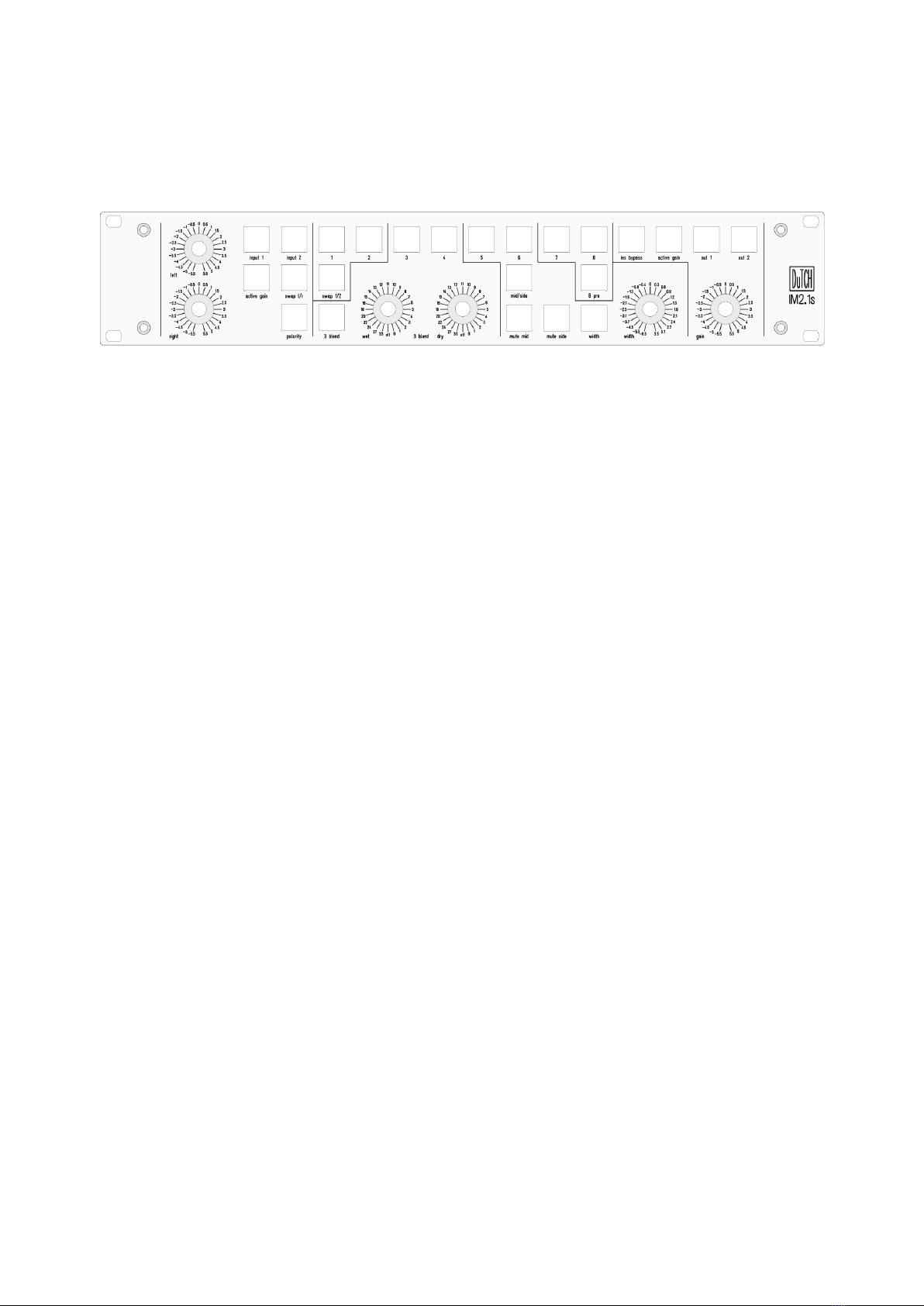
Outputs:
Outputs:
You can choose between the 2 outputs by selecting the corresponding button. It’s also
possible to use both outputs at the sa e ti e, but keep in ind that this could cause so e
i pedance and so level changes.

Ins ypass:
When you engage ‘ins bypass’ all inserts will be bypassed. You will see that all lights on the
insert switches will go out, giving you extra visual feedback. Si ply said, the input section
will go directly to the output.
IM2.1
Bypass offset Out 1:
Out 1 and 2 are passive output selectors with just relays, so no active circuit. So basically,
it’s passing the signal fro the inserts straight into the output. But when you push the ‘out
1 bp offset’, it will bypass all inserts and the active gain stage ‘out 1 offset’ co es active.
The onitor offset will allow you to change the bypass gain to ake up for the processing
of the inserts. This way you can A/B between the analog processing and level- atched
bypassed signal. The gain range is set fro -10dB to +10dB * done with a pot eter
instead of a stepped switch for a ore precise adjust ent. And since this is just an AB
function no recall is needed. Internally the gain range of the onitor tri can be calibrated
with 2 ultiturn tri ers.
* note: the bypass gain range on earlier revisions was -2dB to +8dB
IM2.1s
Active output gain:
The output is passive with just relays, but by pushing the ‘active gain’ button you will
enable the active gain stage which enables you to change the output gain to your liking. In
the id/0 position, there is no gain applied though it passes the active gain circuit. You can
change the gain in 23x0.5dB steps fro +/-5.5dB* with stepped switches.
* note: the gain range for the 0.25dB per step output gain is +/-2.75dB. It’s also
possible to order the IM2.1s with a gain range toggle switch. That way you can
choose between 0.25 and 0.5dB per step.
Rearpanel:
Inputs:
The IM2.1(s) has two balanced inputs. Both inputs consist of gold-plated Neutrik XLR’s.
Inserts:
The IM2.1(s) has 8 balanced inserts connected on the back with industry standard Tasca
DB25 analog connections. Each connector holds 2 inserts corresponding with the frontpanel
nu bering.

* Note: Be careful with DB25 tascam standard/premade cables. The digital AES/EBU
cables have their inputs and outputs swapped compared to the analog version.
Outputs:
On the rearpanel you will find 2 outputs with balanced gold-plated Neutrik XLR’s.
Power:
Power is provided by a standard grounded IEC input connector with a build-in fuse. Input
voltages are auto atically selected fro 100-250VAC 50/60hz.
Tec nical:
Hardware:
This device is built around ostly passive circuits, but so e sections need to be active, but
always with transparency in ind. The sturdy frontpanel-switches have, depending on their
function, 2 color leds for visual feedback. All relays are high sensitive, long-life (15.000.000
cycles) O ron Relays.
Stepped switches are ilitary grade Blore Edwards for long life and really nice echanical
feel. In and output connectors are gold-plated Neutrik, DB25 inserts are gold-plated wurth
connectors. Active circuits ake use of analog devices and THAT drivers. The id/side
circuit is based on the well-known circuit fro Wayne Kirkwood, but with
additions/ odifications.
The internal PSU section is build around industrial-grade Meanwell SMPS’s which run way
ore silent and are way ore efficient then old-school linear PSU’s. Both the relays/leds
and active circuit PSU’s are running on their own separate PSU.
When this device is used in passive ode, so without active stages, it’s 100% passive and
only relay-contacts are inline. This eans it’s basically a straight wire.
Pushswitch la eling:
To have so e extra visual feedback on the push-switches you can put labels under the
switch-covers. You can si ply, but carefully, re ove the switch cover with a s all
screwdriver and put so ething like a transparent dy o letratag sticker on the white plastic
piece inside the switch-cover. More info and a manual can be found on our website.

Specifications:
Maxi u gain passive: >+24dBu
Maxi u gain active gain: +24dBu
Noise level passive: >118dB(a)
Noise level active: >116dB(a)
Stereo crosstalk: >110dB(a)
Stereo crosstalk id/side: >80dB(a)
THD passive: 0.00042% (AD/DA li itations)
THD active: 0.00045%
Input voltage 100 to 240VAC 50/60HZ.
Power consu ption ini u 5 watt
Power consu ption axi u 30 watt
(Power consu ption depends on the a ount of inserts, input, output etc activated)
Unit size: standard 2u 19 inch, depth 25c
Weight: approx 4kg
Specifications subject to change because always improving
Service and warranty:
We offer a standard 2 year li ited warranty on all of our products.
In the event that you or a third party has (partly) altered or repaired anything, the
warranty will expire, and you will be held responsible for the da ages caused by any
possible isfunctioning of the product. Warranty repairs are only ade by us or by a
workshop we agree upon.
We are not responsible for any alfunction of or da age caused by parts that are not
produced by DuTCH.audio.
If you choose to ship back a faulty unit to us you ust contact us before you do so. We
need the serial nu ber (located on the back of the unit) to handle the repair and if
warranty is still valid.
The product should be returned in it's original package or packed in such a way that it
is not da aged during the ship ent with extra support for the rack ears. We are not to
be held responsible for any da ages during the ship ent.
The custo er always pays the shipping cost to us.
The custo er is responsible for the product until it is delivered to us
If we find that the product is flawless the custo er will be charged 200 euro to cover
our costs for exa ination and handling. The return costs will also be charged.
© DuTCH.audio 2021
Hand ade in Holland on Solarpower
contact@dutch.audio
https://dutch.audio
Phone: +31 6 53998686
Table of contents
Other DUTCH Recording Equipment manuals
Popular Recording Equipment manuals by other brands

Real Time Devices
Real Time Devices ERES104 user manual

iCON Pro Audio
iCON Pro Audio Upod Pro user manual

BOSSCO
BOSSCO GT-6B owner's manual

TT Systems
TT Systems Tele-Recorder VTR-700 user manual

Kohler
Kohler K-527 installation guide

Allen-Bradley
Allen-Bradley DeviceNet CompactPCI 1784-CPCIDS installation instructions