1. All pipe work must comply with AS/NZS 3500.4.
2. All solar system pipes must be ½" copper.
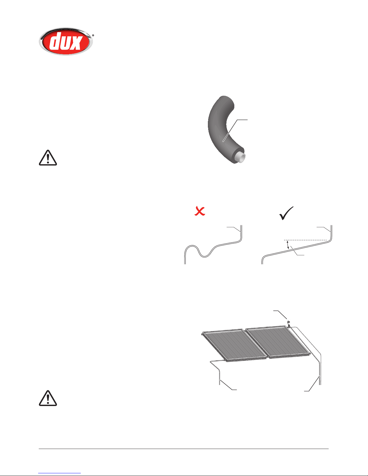
3. Pipes must be fully insulated with UV stabilized
insulation suitable for solar working temperatures,
e.g. Armaflex DuoSolar / Solar insulation.
4. Pipes from the solar collectors to the water storage tank
must have a minimum of 5° continuous fall, to allow the
water to easily drain out of the pipes.
5. A solar non return valve is supplied, and MUST be fitted
to the return from the collectors, as per the supplied
Installer’s Guide.
Min
500mm
Valve
Train
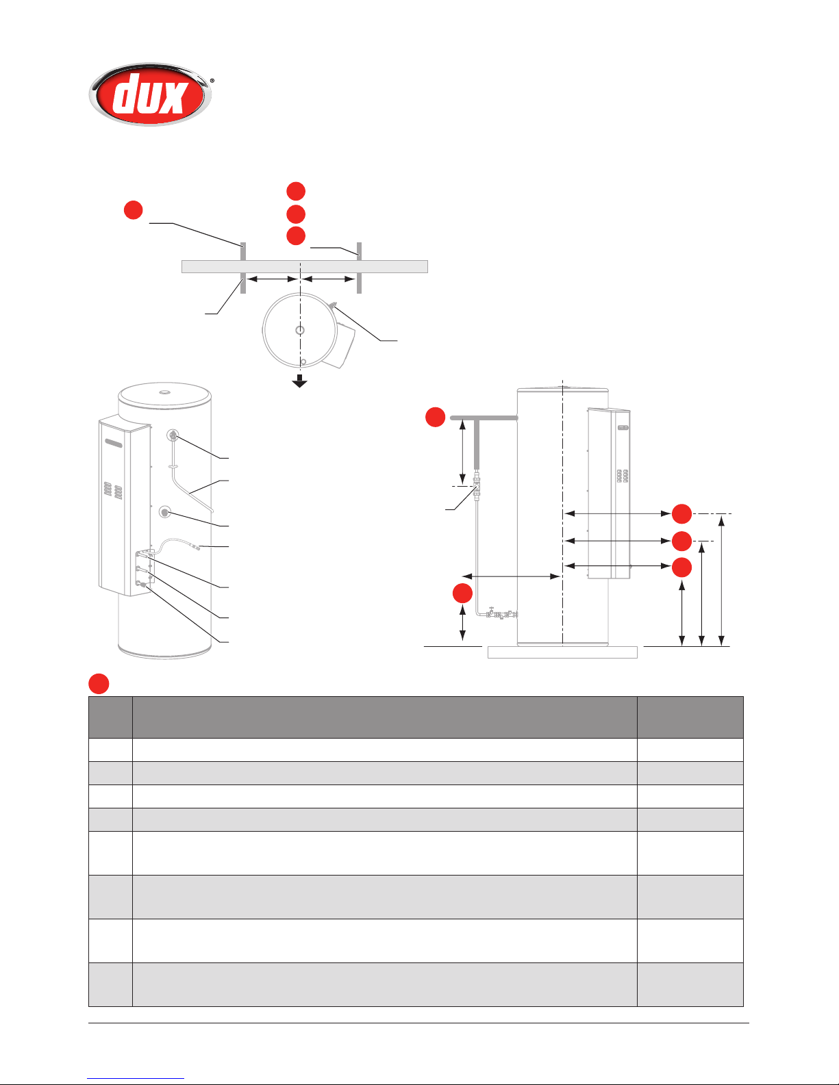
C1
C
A
Tempering
Valve
C2
Return from solar collectors
PTR valve
Collector temperature sensor.
See Installer’s Guide for sensor
installation instructions
To solar collector
Gas Inlet
Plumb to waste to comply with AS/NZS 3500.4
and local plumbing codes. Treat as a PTR valve.
Plumb to waste to comply with AS/NZS
3500.4 and local plumbing codes
Wall
Return from solar collectors
Flow to solar collectors
Gas pipe
Cold water inlet
450mm
Front of heater
350mm
C
B
D
E
PTR valve
Ensure pipes protrude
horizontally from wall, and
leave enough length of pipe to
allow easy connections
Approximate location of pipework (rounded to the nearest 10mm). A tolerance of 25mm is acceptable to dimensions shown in table.
Rough In Diagram
DN15DS,
DL15DS
Capacity 324 L
Tank Height 1754
Overall diameter 617
A Untempered hot water outlet from top of fireproof slab 1541
B Return from solar collectors from top of fireproof slab B1
Return from solar collectors from centre line of tank B2
1013
450
CCold water inlet from top of fireproof slab C1
Cold water inlet from centre line of tank (allowing space for valve train) C2
215
350
DFlow to solar collectors from top of fireproof slab D1
Flow to solar collectors from centre line of tank D2
640
450
EGas entry from top of fireproof slab E1
Gas entry from side of tank E2
540
450


 null")
 null")


 Operation and maintenance instructions")