Adjusting and Framing-Up the Camera View
1. Camera Access and Login:
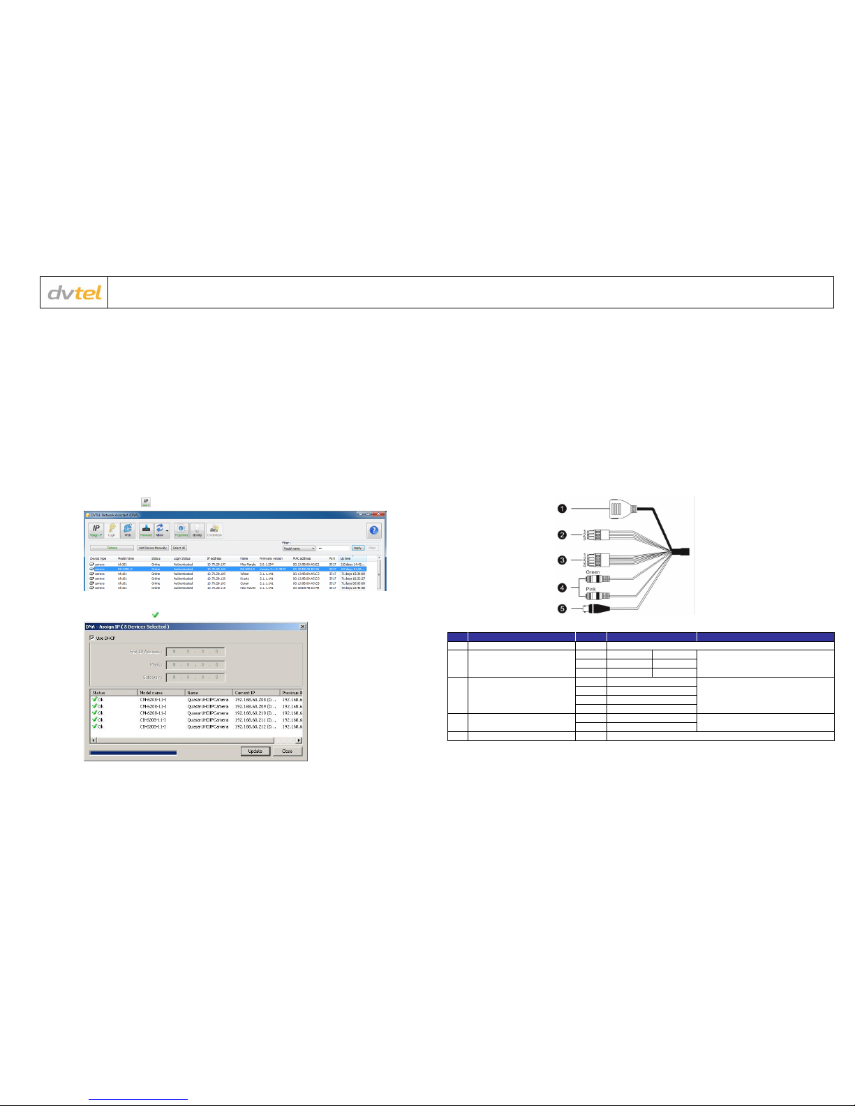
Access the camera in one of the following ways:
a. If using the DNA application, click the DNA icon . In the Discovery List, click to select the camera, right-click to open the
shortcut menu, and select Browse.
b. If using a web browser, enter the camera’s IP address in the address bar.
2. Before logging into the camera:
The client application is automatically installed when you connect to the camera through your PC/workstation web-browser for the
first time. Before accessing the camera, ensure that ActiveX controls can be downloaded by (a) changing the ActiveX controls and
plug-in settings or (b) setting the Internet security level to default. For further details, refer to the camera’s User and Installation
Guide.
ActiveX Controls and Plug-in Settings
Step 1: Start Internet Explorer (IE 9, 10, or 11).
Step 2: Select Tools from the main menu of the
browser. Then click Internet Options.
Step 3: Select the Security tab and click Internet.
Then click Custom level to change ActiveX
settings.
Step 4: Set all ActiveX controls and plug-ins
settings to Prompt or Enable.
Step 1: Start Internet Explorer (IE 9, 10, or 11).
Step 2: Select Tools from the main menu of the
browser. Then click Internet Options.
Step 3: Select the Security tab and click Internet.
Step 4: Click Default level. Click OK to confirm the
setting. Close the browser window. Open a
new window later to access the IP camera.
3. Camera Login:
See the section titled Initial configuration for instructions on setting the cameras IP address.
4. Login ID and Password:
a. Enter the camera’s IP address in the browser’s address bar and press the Enter key.
b. Enter the default user name (Admin) and password (1234).
NOTE: The user name is case-sensitive.
5. Install the ActiveX control:
a. After accessing the camera through the web browser for the first time, a request to install the ActiveX control appears
below the address bar.
b. Right-click on the information bar, and select Install ActiveX Control…to permit ActiveX control installation.
c. In the pop-up security warning, click Install to start downloading the DVPlayer software onto the PC.
d. Click Finish when the DVPlayer installation is completed.
NOTE: Before accessing the camera, if you have previously installed an older version of the DVTEL Web Player (DVPlayer) on the PC,
use the Windows Add/Remove program to uninstall the existing DVPlayer from the PC. For more information, refer to the camera’s
User and Installation Guide.
Attach in Latitude
1. In the Latitude application, on the sidebar click Physical View.
2. On the Navigation Tree click the System name.
3. Select the Discovery tab and do the following:
a. Under Cameras and Encoders, verify that DVTEL Quasar Gen II
is selected.
b. Click Start. The camera details are displayed in the Discovery table.
c. If the camera wasn’t found after running Start, click Discover
Unit Manually.
d. In the dialog box that opens, enter the camera’s IP address,
select DVTEL Quasar Gen II and click OK.
4. In the Discovery table, right-click the camera, choose Attach, and then click
the Archiver name to attach.
5. When finished, click to save.
Models in the CB Series:
QHD 1440p indoor/outdoor bullet IP camera, 3-8mm, F1.4 lens with 96-38° horizontal viewing angle
QHD 1440p indoor/outdoor bullet IP camera, 7-22mm, F1.4 lens with 42-14° horizontal viewing angle
UHD 4K indoor/outdoor bullet IP camera, 3.5-8mm F1.4 lens with 116-50° horizontal viewing angle
UHD 4K indoor/outdoor bullet IP camera, 9-22mm F1.4 lens with 45-18° horizontal viewing angle
How to Contact DVTEL:
North America: 1-888-DVTel77
Latin America: +52 555580 5618
EMEA: +44 (0) 1494 430240
APAC: +65 6389 1815
China: +86 10 8586 8836
India: +91 (129) 431 5031
ANZ/Pacific: +61 8 8235 9211
For assistance, email us at support@dvtel.com or visit http://www.dvtel.com/support.
© DVTEL, Inc. All rights reserved worldwide. Printed March 2015