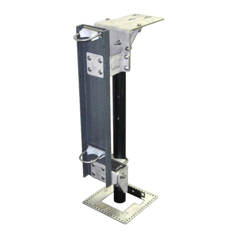
DX Engineering DXE-RDPK-160 User manual
Other DX Engineering Antenna manuals

DX Engineering
DX Engineering DXE-160VA-1 User manual
DX Engineering
DX Engineering Thunderbolt DXE-7580VA-1 User manual
DX Engineering
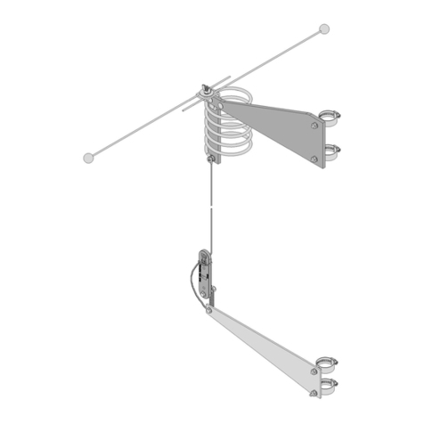
DX Engineering DXE-AOKC-17M User manual

DX Engineering
DX Engineering MFJ-1734 User manual

DX Engineering
DX Engineering SkyHawk 3X10 User manual
DX Engineering
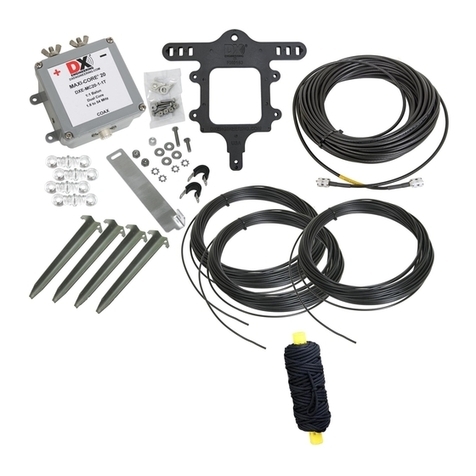
DX Engineering DXE-NVIS-8040NM User manual
DX Engineering
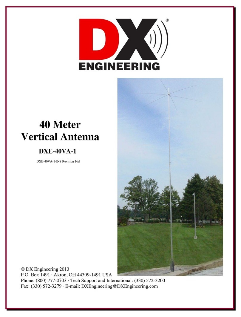
DX Engineering DXE-40VA-1 User manual
DX Engineering
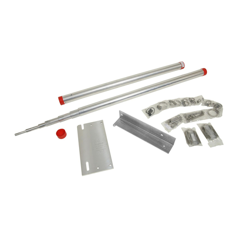
DX Engineering DXE-MBVE-5A User manual
DX Engineering
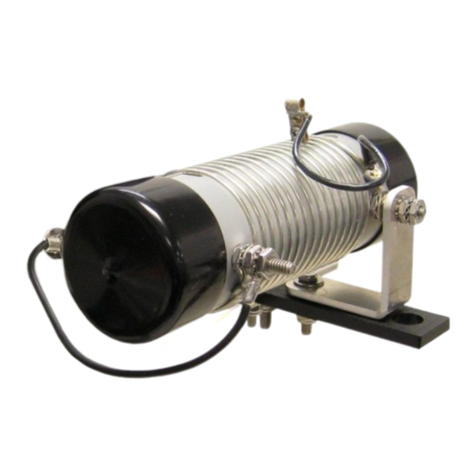
DX Engineering DXE-SA80-AOK User manual

DX Engineering
DX Engineering DXE-PS-2B-P User manual
DX Engineering
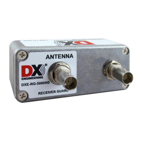
DX Engineering DXE-RG-5000HD User manual
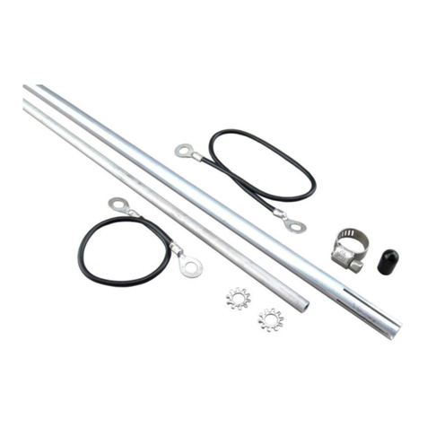
DX Engineering
DX Engineering DXE-MBVE-5A User manual
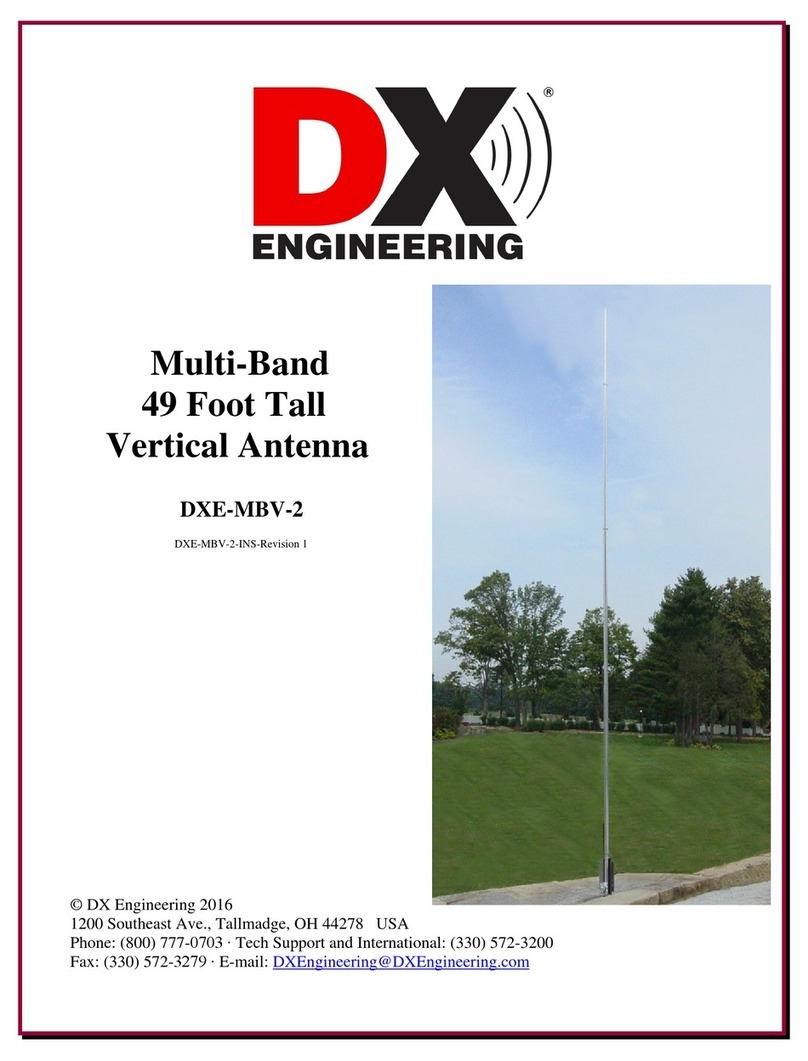
DX Engineering
DX Engineering DXE-MBV-2 User manual
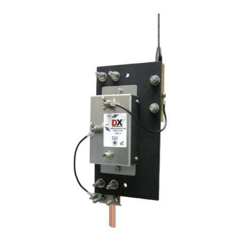
DX Engineering
DX Engineering DXE-ARAV3-1P User manual

DX Engineering
DX Engineering Hot Rodz DXE-HR-1P User manual

DX Engineering
DX Engineering OMNI-TILT DXE-OMNITILT-1 User manual
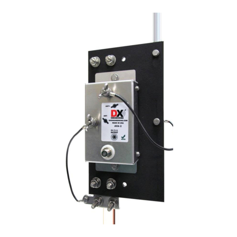
DX Engineering
DX Engineering DXE-ARAV4-1P User manual

DX Engineering
DX Engineering DXE-VGMT-3CG User manual

DX Engineering
DX Engineering DXE-OCF-KIT User manual
DX Engineering
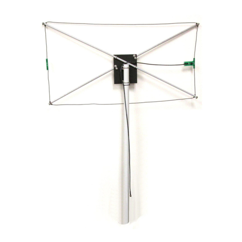
DX Engineering DXE-NOISELOOP-INS Series User manual
Popular Antenna manuals by other brands

DAVIS
DAVIS Windex AV 3160 installation instructions

Belden
Belden Hirschmann BAT-ANT-N-14G-IP23 Mounting instruction

Vtronix
Vtronix YHK Fitting instructions

KVH Industries
KVH Industries TracVision 6 Technical manual

Leica Geosystems
Leica Geosystems GS10 user manual

Sirio Antenne
Sirio Antenne Gain-Master manual

Feig Electronic
Feig Electronic ID ISC.ANTH200/200 Series manual

TERK Technologies
TERK Technologies TV44 owner's manual

TERK Technologies
TERK Technologies SIR3 owner's manual

Directive Systems & Engineering
Directive Systems & Engineering DSE2324LYRMK quick start guide

HP
HP J8999A instructions

MobilSat
MobilSat MSP-S Mounting instructions
