manuals.online logo
Brands
  1. Home
  2. •
  3. Brands
  4. •
  5. DX Engineering
  6. •
  7. Antenna
  8. •
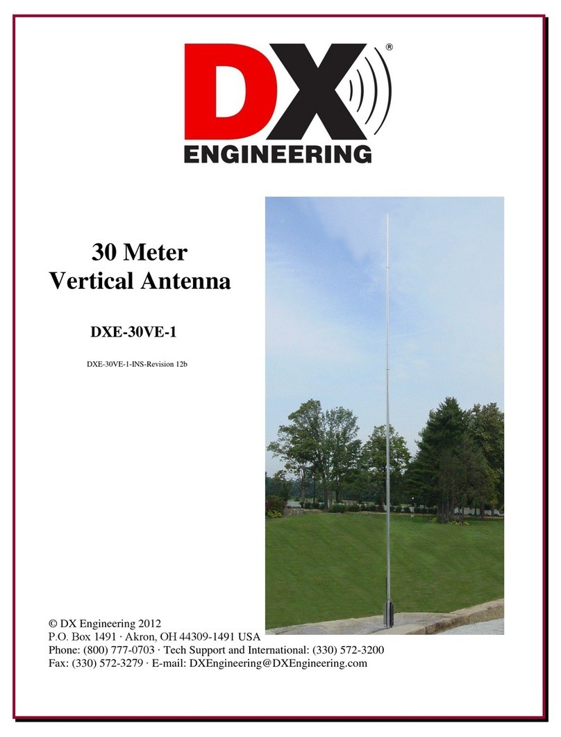
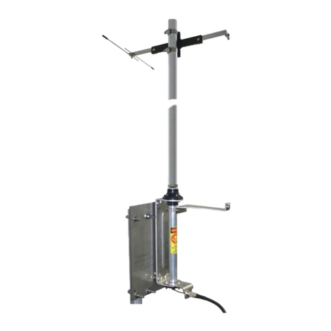
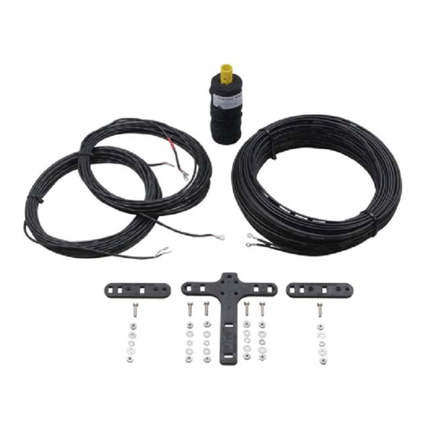
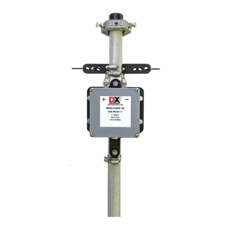
  9. DX Engineering Hummelmasten Mini XL User manual

DX Engineering Hummelmasten Mini XL User manual

e-mail: [email protected]
www.hummelmasten.de
Seite
Hummelmasten, 75417 Mühlacker, Industriestr. 14/1
Tel. +49-7041-45 2 44, Fax -86 43 08
Easy Step by Step
Manual
Teletower
Mini XL
Wall-Floor
installation
e-mail: [email protected]
www.hummelmasten.de
Seite
Hummelmasten, 75417 Mühlacker, Industriestr. 14/1
Tel. +49-7041-45 2 44, Fax -86 43 08
The tower packages #1-#2-#3
e-mail: [email protected]
www.hummelmasten.de
Seite
Hummelmasten, 75417 Mühlacker, Industriestr. 14/1
Tel. +49-7041-45 2 44, Fax -86 43 08
Open Base Package #1 for the main tower parts.
Here you see the three tower tubes (H-Head, M-Middle, F-Feed)
and the side steam of the carriage (No.34 on them)
e-mail: [email protected]
www.hummelmasten.de
Seite
Hummelmasten, 75417 Mühlacker, Industriestr. 14/1
Tel. +49-7041-45 2 44, Fax -86 43 08
Next Step:
Open Base Package #2
There are this parts inside
e-mail: [email protected]
www.hummelmasten.de
Seite
Hummelmasten, 75417 Mühlacker, Industriestr. 14/1
Tel. +49-7041-45 2 44, Fax -86 43 08
Base Package #3 got the wall bracket and the feedange of the tower.
All screws an nuts to build them are inside.
e-mail: [email protected]
www.hummelmasten.de
Seite
Hummelmasten, 75417 Mühlacker, Industriestr. 14/1
Tel. +49-7041-45 2 44, Fax -86 43 08
Take one screw with one washer on it.
Stuck it into No.5 the other in No.3 and
make one more washer on it.
Screw them together No 5 to No 6 No 3
to No 4, one more washer and the stop
nut. Now Fix ist together with 2 13 mm
Key´s open them a quarter so the No 5
and 3 can turn.

of the long tower tubes.
e-mail: [email protected]
www.hummelmasten.de
Seite
Hummelmasten, 75417 Mühlacker, Industriestr. 14/1
Tel. +49-7041-45 2 44, Fax -86 43 08

you have to sign the 99 inch or 2.5
-
ket.
You can go higher if you want but
99 in-
Now make the wallbrak-
ket ready
Only the back
two screws are
loosen inside.

2.5 meter sign you make a few streps before.
Now you can screw it with the other 2 screws.
Fix it total now M8=25 N M12=82 N
e-mail: [email protected]
www.hummelmasten.de
Seite
Hummelmasten, 75417 Mühlacker, Industriestr. 14/1
Tel. +49-7041-45 2 44, Fax -86 43 08
Go to the position of the tower, errect it ( only feed



e-mail: [email protected]
www.hummelmasten.de
Seite
Hummelmasten, 75417 Mühlacker, Industriestr. 14/1
Tel. +49-7041-45 2 44, Fax -86 43 08
FMH
You take now the coupling parts and screw them loosen into the F and M tubes.
e-mail: [email protected]
www.hummelmasten.de
Seite
Hummelmasten, 75417 Mühlacker, Industriestr. 14/1
Tel. +49-7041-45 2 44, Fax -86 43 08
Fix the wall bracket,
take only the back 2 screws into it. When tower is erected you x the both infront.
e-mail: [email protected]
www.hummelmasten.de
Seite
Hummelmasten, 75417 Mühlacker, Industriestr. 14/1
Tel. +49-7041-45 2 44, Fax -86 43 08
Pull the carriage on the head tube.

pulley.
No.34 or side steams you
have to mount now.
Take the winch, read instructions for install the
crank on it. Here you see the parts you need for
It is only possible to put the
screws from behind into MW1
see this picture.
Segments:
The nuts in the foot segment
Loosely screw in. The next segment
Push it loose, loosely here as well
They can be aligned. Compensate transitions!
Only then are the screws tightened with tor-
que. The head segment is now assembled in
the same way.
e-mail: [email protected]
www.hummelmasten.de
Seite
Hummelmasten, 75417 Mühlacker, Industriestr. 14/1
Tel. +49-7041-45 2 44, Fax -86 43 08
Manual of winch
Fixed winch on the tower
take the wire between tower and
carriage to the head plate, from
there to the right.
Very Important!!!!!
Make this at both carriage parts.
e-mail: [email protected]
www.hummelmasten.de
Seite
Hummelmasten, 75417 Mühlacker, Industriestr. 14/1
Tel. +49-7041-45 2 44, Fax -86 43 08
Here at the lower carriage part.
The wire is going to the winch and

Now you can crank it so the wire is strange to the carriage.
This is the moment when you can x the feedanch No3 and 5.
Now you can errect the tower into the wall bracket.
When it is there you x the wallbracket screws infront of the tower. Now there is the save
position you have to x the feedange.
e-mail: [email protected]
www.hummelmasten.de
Seite
Hummelmasten, 75417 Mühlacker, Industriestr. 14/1
Tel. +49-7041-45 2 44, Fax -86 43 08
MOUNTING:
Basics: All screws are tightened with standard torque! M8 25 Newton / meter, M12 86
Newton / meter
M 12 x 30
Coupling in section
Headplate NR.42 Handwinch
Wi1
Wi2
Segments:
The nuts in the foot segment
Loosely screw in. The next segment
Push it loose, loosely here as well
They can be aligned. Compensate transitions!
Only then are the screws tightened with tor-
que. The head segment is now assembled in
the same way.
Head
In the case of the coupling
lugs, the fan discs come
under the screw head.
e-mail: [email protected]
www.hummelmasten.de
Seite
Hummelmasten, 75417 Mühlacker, Industriestr. 14/1
Tel. +49-7041-45 2 44, Fax -86 43 08
Slide the carriage level rotator and bearing together and place them on the mast:
The slide levels are pushed from the head to the mast.
There are inlets which facilitate the sliding on.

First, the rotor plane with the connections on the ball bearing blocks comes upwards.

the body. She is pushed with a thrust of the hands.
If the carriage is too tight, proceed as follows.
To open the preload, as shown in the sketch below, loosen the 8 mm screws between 50x50x4
brackets and ball bearing blocks and allow the sled to bounce slightly. After being pushed on, the
screws must be tightened with the saddle tensioned.
- The ball bearings should not be rotated by hand after being pushed -
And on the mast without play.
The slide levels are bolted to the side handles No. 34. The M 8 screws are mounted from the
outside to the inside, and the ratchet nuts come inwards.
If the sled runs with light resistance it is good.

For the test drive of the sled after the erection of the mast, hang a line on the sled to allow the
pull down. Later, with the rotor, the upper bearing and the antenna system, the sled is running
down by its own weight.
The top plate No. 42 is screwed on the top of the mast.
Type Hand winch, mount the rope:

Care and Maintenance :
The entire mast and carriage construction is extremely long-term corrosion-proof thanks to the

e-mail: [email protected]
www.hummelmasten.de
Seite
Hummelmasten, 75417 Mühlacker, Industriestr. 14/1
Tel. +49-7041-45 2 44, Fax -86 43 08
Installation of the mast:
CAUTION: First, lock the carriage in the uppermost position on the horizontal slide block.
The rear tensioning screws are inserted into the upper wall bracket. So we have a stop after set-
ting up.

The installation is the same for both types of masts.

wall bracket.

Then all the pipe clamping screws are used.
Rotor & top bearing:
Set the sled lock vertically and crank the sled downwards. Now the rotor holes on parts 13 and



The tilt direction can be from right, left or to the wall.
The upper wall holder is set as high as possible in order to achieve the largest possible clamping
length.
The mast is aligned vertically with the water carriage and the dowel holes are drawn.
Drill with 14 mm diameter.
To install the wall brackets, use the supplied Fischer anchors S14H 135R and screws.
Mounting the wall bracket:
According to sketch
60
61
62 2x
M12x30
4x M 8x150
Mast clamp
1
26
3
5
4
Mast
Mast

This manual suits for next models

1

Other DX Engineering Antenna manuals

DX Engineering EZ-Build DXE-UWA-KIT User manual

DX Engineering

DX Engineering EZ-Build DXE-UWA-KIT User manual

DX Engineering DXE-ARAV4-1P User manual

DX Engineering

DX Engineering DXE-ARAV4-1P User manual

DX Engineering DXE-8040-30AOK User manual

DX Engineering

DX Engineering DXE-8040-30AOK User manual

DX Engineering DXE-MBVE-5A User manual

DX Engineering

DX Engineering DXE-MBVE-5A User manual

DX Engineering DXE-4030VA-1 User manual

DX Engineering

DX Engineering DXE-4030VA-1 User manual

DX Engineering DXE-7580FS-VA-3 User manual

DX Engineering

DX Engineering DXE-7580FS-VA-3 User manual

DX Engineering OMNI-TILT DXE-OMNITILT-1 User manual
DX Engineering

DX Engineering OMNI-TILT DXE-OMNITILT-1 User manual

DX Engineering DXE-PS-2B-P User manual

DX Engineering

DX Engineering DXE-PS-2B-P User manual

DX Engineering DXE-30VE-1 User manual

DX Engineering

DX Engineering DXE-30VE-1 User manual

DX Engineering DXE-NOISELOOP-INS Series User manual

DX Engineering

DX Engineering DXE-NOISELOOP-INS Series User manual

DX Engineering DXE-RG-5000HD User manual

DX Engineering

DX Engineering DXE-RG-5000HD User manual

DX Engineering Hexx XB-5 User manual

DX Engineering

DX Engineering Hexx XB-5 User manual

DX Engineering DXE-MBVE-2 User manual

DX Engineering

DX Engineering DXE-MBVE-2 User manual

DX Engineering DXE-VA-PIVOT-3 User manual

DX Engineering

DX Engineering DXE-VA-PIVOT-3 User manual

DX Engineering HEXXAGONAL BEAM Mark 2 User manual

DX Engineering

DX Engineering HEXXAGONAL BEAM Mark 2 User manual

DX Engineering DXE-AOK-17M User manual

DX Engineering

DX Engineering DXE-AOK-17M User manual

DX Engineering DXE-40VE-1 User manual

DX Engineering

DX Engineering DXE-40VE-1 User manual
DX Engineering DXE-MBVE-1UGBRT3 User manual

DX Engineering

DX Engineering DXE-MBVE-1UGBRT3 User manual

DX Engineering DXE-MBVE-1 User manual

DX Engineering

DX Engineering DXE-MBVE-1 User manual

DX Engineering SkyHawk 3X10 User manual

DX Engineering

DX Engineering SkyHawk 3X10 User manual

DX Engineering DXE-MBV5AS-INS User manual

DX Engineering

DX Engineering DXE-MBV5AS-INS User manual

DX Engineering DXE-RRMX2X8 User manual
DX Engineering

DX Engineering DXE-RRMX2X8 User manual

DX Engineering DXE-60VA-1P User manual

DX Engineering

DX Engineering DXE-60VA-1P User manual

DX Engineering DXE-AOKC-17M User manual

DX Engineering

DX Engineering DXE-AOKC-17M User manual

Popular Antenna manuals by other brands

Matsing MS-MBA-3-T4A2 instruction manual

Matsing

Matsing MS-MBA-3-T4A2 instruction manual

ZyXEL Communications ZYAIR EXT-108 Dimensions

ZyXEL Communications

ZyXEL Communications ZYAIR EXT-108 Dimensions

Samsung RRH-2WB installation manual

Samsung

Samsung RRH-2WB installation manual

Pts E-Kit PRC-117G user guide

Pts

Pts E-Kit PRC-117G user guide

GAP Titan manual

GAP

GAP Titan manual

RFI FSA40-67-DIN Installation

RFI

RFI FSA40-67-DIN Installation

Televes 1335 manual

Televes

Televes 1335 manual

Goobay DVB-T DIA 220 PS Mini black Assembly instructions

Goobay

Goobay DVB-T DIA 220 PS Mini black Assembly instructions

iBeam ISD710 quick start guide

iBeam

iBeam ISD710 quick start guide

RCA ANT537 - TV Antenna - Indoor user guide

RCA

RCA ANT537 - TV Antenna - Indoor user guide

Plantec K60ZAD manual

Plantec

Plantec K60ZAD manual

RF Elements CC Series manual

RF Elements

RF Elements CC Series manual

CUSHCRAFT R9 Assembly and installation instructions

CUSHCRAFT

CUSHCRAFT R9 Assembly and installation instructions

Hama 121696 operating instructions

Hama

Hama 121696 operating instructions

Antop OMNIPRO Series installation instructions

Antop

Antop OMNIPRO Series installation instructions

Codan C463 installation manual

Codan

Codan C463 installation manual

MFJ Super Hi-Q Loop instruction manual

MFJ

MFJ Super Hi-Q Loop instruction manual

PRO.SIS.TEL. PST-53-40 Assembly instructions

PRO.SIS.TEL.

PRO.SIS.TEL. PST-53-40 Assembly instructions

manuals.online logo
manuals.online logoBrands
  • About & Mission
  • Contact us
  • Privacy Policy
  • Terms and Conditions

Copyright 2025 Manuals.Online. All Rights Reserved.