DX Engineering DXE-RTR-2 User manual

2
Table of Contents
Introduction
3
Features
4
The Amateur Radio Dilemma and the DX Engineering RTR-2 Solution
5
RTR-2 Technical Description and Functions
5
Internal Option Slots
5
Option 1 - DXE-IT-PM
5
Option 2 - DXE-RG5000HD-PM
6
Option 3 - DXE-RPA-2PM
6
Internal Relay Connections and Functions
6
Front Panel Controls and Indicators
9
Rear Panel Connections
10
More On RADIO PTT –RX ENABLE Failsafe Feature
11
KEYING LINE CONNECTION WARNING
13
Internal Jumpers
14
Bias Tee Enable
15
Force Ground
15
Bias Tee Always On
16
Removing Bypass Plug-in Boards
17
Installing Internal Option Modules
18
RTR-2 Installation
19
Connections
19
Receiving Antenna Spacing Guidelines
20
Typical System Configurations
21
Interconnection Diagrams
22
Additional System Configurations
25
Specifications
34
Optional Plug-in Module Descriptions and Specifications
34
User Diagram
35
Technical Support
36
Manual Updates
36
Warranty
36

3
Introduction
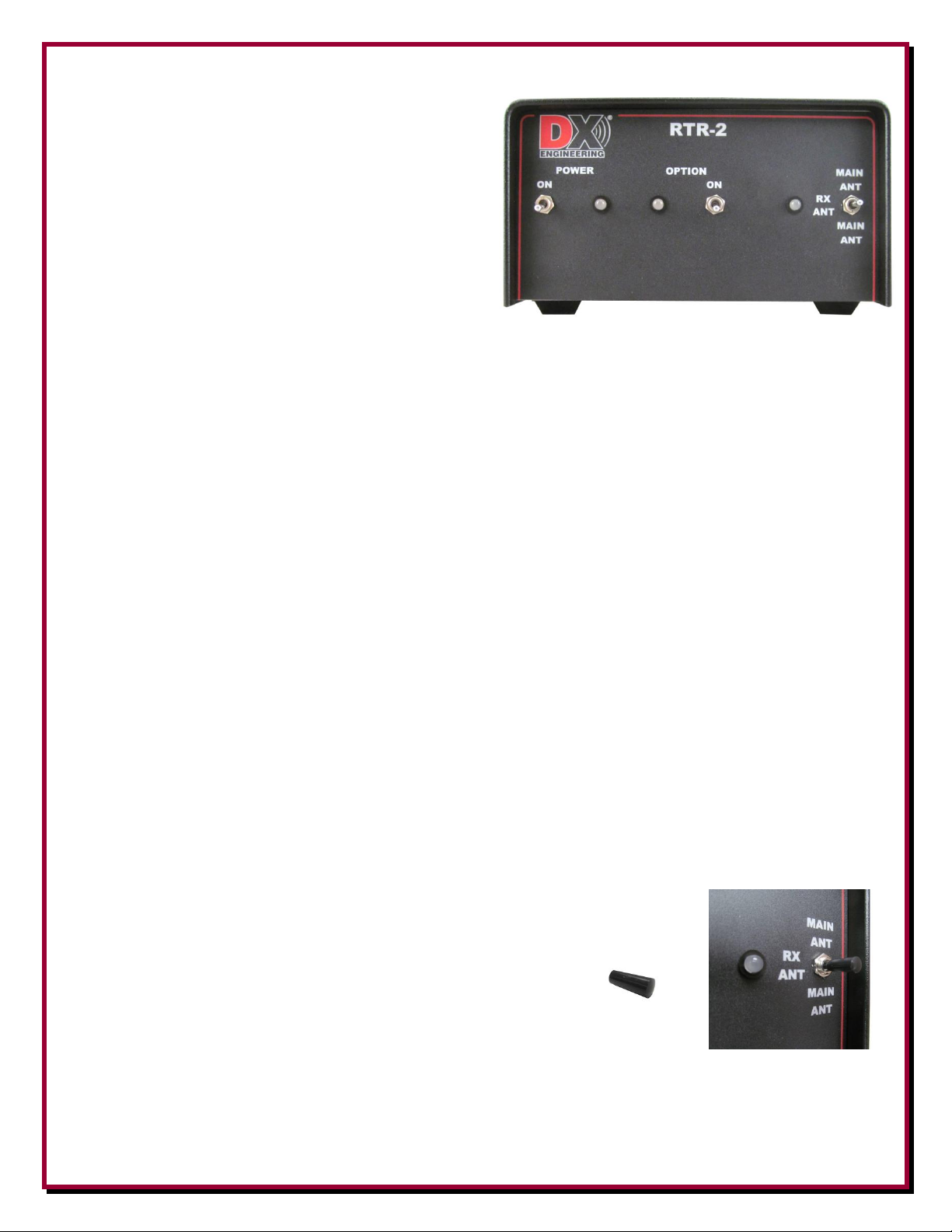
The DX Engineering DXE-RTR-2 Modular Receive Transmit Interface is an innovative, multi-
purpose relay unit that automatically switches the RF output connector on any HF transceiver
between a receiving antenna system and a standard transmitting antenna. A front panel mode switch
allows the operator to listen to either antenna system. It provides the safest and most versatile
method of connecting a receive antenna to any general coverage receiver, but it most often used
with HF transceivers that do not have a separate receive antenna input.
The DXE-RTR-2 has a new design that features three internal slots for optional accessory modules
to improve receive system connections, provide receiver front-end protection and to dramatically
enhance low-signal receive antenna performance.
75 to 50 ohm Impedance Transformer Plug-in Module, DXE-IT-PM
Receiver Guard Plug-in Module, DXE-RG5000HD-PM
Receive Preamplifier Plug-in Module, DXE-RPA-2-PM
The DXE-RTR-2 is a very useful
antenna relay unit for many
applications, such as adding our low-
noise, high dynamic range receive
preamplifier to any transceiver or
receiver, as requested by Amateurs
and SWLs. Or, add failsafe receiver
protection for stations with close-
spaced transmit and receive antennas.
This unit protects and safely connects
any transceiver to any antenna that
can be used for receiving, including
Beverage, Pennant, Flag, a passive
loop or a sophisticated Receive
Array. Plus, it supplies keyed, bias-
tee voltage on the receive antenna input for all types of powered receive antennas including the
Active Receive Vertical, DXE-ARAV3-1P and the Active Magnetic Loop, DXE-RF-PRO-1B.
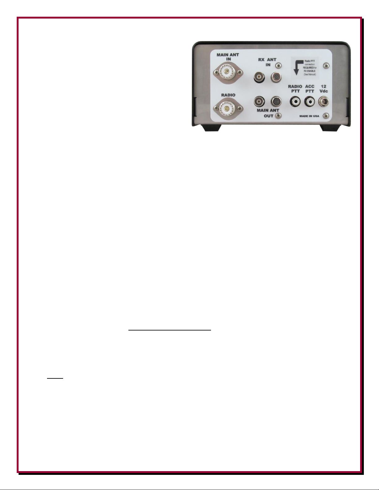
One of the most important features of the DXE-RTR-2 is its unique, failsafe relay system that
protects the unit, the plug-in modules, and the receive antenna equipment from transceiver RF
output damage. The receive antenna mode (RX ANT) is only allowed when the dual-purpose
keying line from the transceiver is connected, carrying the special RX ENABLE output signal on
the keying line shield to the transceiver chassis. This is the failsafe interlock. Then, as soon as the
transceiver is keyed (or the unit loses power), the RF output from the transceiver is automatically
diverted to the transmit antenna connection. The very fast acting relay (about 4 ms) in the RTR-2
diverts the transceiver output (up to 200 watts CW) fast enough for QSK, full break-in CW (use
partial break-in CW operation when using Bias Tee powered active receive antennas), while
listening to a receive antenna. It prevents the hot switching and timing errors that are common on
other transmit/receive relays, especially dangerous RF sense circuits.

4
For normal operation, the RTR-2 requires the RADIO PTT –RX ENABLE keying cable to be
installed. It can be as simple as a common RCA patch cable connection on transceivers that have a
keying connector RCA shell at chassis ground. Most other transceivers’ keying common is tied to
the transceiver chassis. The exception is most Kenwood transceiver keying relays with floating
common. To facilitate connections to most Kenwood 7-pin DIN Remote connectors, a new keying
line cable is available from DX Engineering, the DXE-KWD-RTR. This special cable assembly
allows proper operation of a Kenwood transceiver with the RTR-2. See more details in manual
sections entitled “RTR-2 Technical Description and Functional” and “More on Radio PTT – RX
Enable Failsafe Feature.”
Note: Every radio manufacturer’s accessory interconnection scheme is different. Consult
your radio manufacturer’s manual for details and requirements for receive signal inputs,
outputs and switching voltages.
Features of the DXE-RTR-2 Receive Transmit Interface:
Attractive and heavy stainless steel enclosure
Multi-Color Status Indicating LEDs for Power, Option Power and Mode
Safe switching - automatically connects radio to transmit antenna when dc power is off
Hot switching lockout –disconnects receive antenna during transmit mode
Adds protection and antenna switching flexibility, even for transceivers with receive ports
Connects transmit antenna to second receiver (MAIN ANT OUT) when transceiver is
listening to receive antenna
Handles up to 200 watts (CW) of transmit RF
Fast relay supports QSK, full break-in CW (use partial break-in CW operation when using
Bias Tee powered active receive antennas)
Transceiver amplifier keying line input RCA female, RADIO PTT with RX Enable output
supports RTR-2 failsafe
Accessory keying line output RCA female (ACC PTT) ‘ground on transmit’ Schottky diode
isolated pass-through from RADIO PTT transceiver amp keying for Amplifier or Accessory
Three internal option slots for Plug-In Modules
Internal 50 ohm impedance –rear panel SO-239 for RADIO and MAIN ANT
Receive Antenna Input –BNC for 50 ohm and F connector for 75 ohm feedlines (use 75 to
50 ohm Impedance Transformer Plug-In Module - DXE-IT-PM)
Internal jumpers to enable and lock bias-tee DC power injection onto receive feedline for
Active Vertical or Magnetic Loop Antennas and to lock receive mode (disable failsafe)
Screw-on version of the DC power connector is provided to prevent accidental power cable
pull-out (standard type 2.1 mm DC power connector may be used)
Operates on +13.8 Vdc nominal, accepts and operates on any voltage from +13 to +21 Vdc input to
power the RTR-2 and Active antennas connected (voltage may have to be higher for long
feedlines). DX Engineering Active Magnetic Loops require +21 Vdc and DX Engineering Active
Receive Verticals require +13.8 Vdc minimum.

5
The Amateur Radio Dilemma and the DX Engineering RTR-2 Solution
The benefits of using separate receiving antennas for “low-band” HF operations have been known
for many years. Low band enthusiasts know that typical transmitting antennas collect too much
noise for reception, especially for DXing on the 160 and 80 meter bands. But, affordable HF
transceivers have been designed without any provision for a receive antenna connection. Otherwise
very capable transceivers, even brand new models, lack a built-in receive antenna port and relay
system. Unfortunately, only the most expensive HF transceivers have a separate receive antenna
input. Even many “high-end” radios do not provide adequate switching between the receive antenna
and the default transmit antenna, or they do not interrupt the receive antenna input during transmit.
To obtain a separate receive antenna input, certain models required optional equipment or modules
which are no longer available.
Now, with the DXE-RTR-2 Receive Transmit Interface, the joy of low-noise, low-band reception
with a separate receive antenna is available to all transceiver and receiver owners. This unit offers a
special receive antenna connection solution, with RF overload protection and improved
preamplification, which incorporates safeguards and switching flexibility. Typical homebrew and
commercial transmit/receive (T/R) relays and other receive switching solutions offer little or no
protection to the receive antenna equipment. The DXE-RTR-2 allows instantaneous receive
comparisons between the receive antenna and the transmit antenna, with a convenient three-position
front panel switch. Multi-color Status LEDs on the front panel allow the user to determine at a
glance if the unit is connected to power, turned on, if the keying cable is properly connected, when a
receive or transmit antenna is selected for reception and when the unit is keyed for transmission.
RTR-2 Technical Description and Functions
The DX Engineering RTR-2 Modular Receive Transmit Interface is an indispensable accessory for
the radio enthusiast and is useful for any Amateur to expand the capabilities of their transceiver or
receiver. It is a specialized multi-port relay unit with one RF transmit capable input and output and
one receive antenna input, and a special purpose output. Here is a detailed description of specific
technical aspects and functions of the RTR-2.
Internal Option Slots
The BNC and F connectors at RX ANT IN are in parallel and are connected directly to the RTR-2
Option Slots. Bypass Plug-In boards are in place to carry input RF directly to the RTR relay. The
DX Engineering Plug-In Modules function exclusively for the receive antenna input operational
protection and enhancements. There are three slots for the following order of option installation:
Option 1 –the top slot is intended for the 75 to 50 ohm Impedance
Transformer (DXE-IT-PM) when the receive antenna 75 ohm feedline
is connected to either the F connector or the BNC connector RX ANT
IN.Without the transformer, either input is 50 ohms, which is the
internal impedance of the RTR-2.

6
Option 2 –middle slot may be used for the Receiver Guard Plug-In
Module (DXE-RG5000HD-PM) when high RF signal levels are
anticipated to occur on the receive antenna input.
Option 3 –bottom slot, switched and powered is reserved for Receive
Preamplifier Plug-In Modules (DXE-RPA-2-PM) as controlled by the
Option Power switch. When the RTR-2 is used with passive receive
antennas or an Active Receive Vertical (DXE-ARAV3-1P), the
installation of the RPA-2 plug-in modules is highly recommended to
enhance low signal levels due to propagation and atmospheric conditions.
See the section on Removing Bypass Plug-in Boards and the section on Installing Optional Modules
Internal Relay Connections and Functions
The RTR-2 high-speed relay toggles the MAIN ANT IN and RADIO connectors simultaneously.
This is a reverse-logic relay which prevents the RADIO connection to the optional modules and RX
ANT IN receive signal unless certain connections are met, to prevent the transmitted RF from
causing damage.
In Figure A, the RTR-2 is in MAIN ANT transmit mode. MAIN ANT IN is internally connected
to the RADIO when the power is turned Off.
The RTR-2 stays in the transmit mode and the mode LED changes to Red when:
An antenna is connected to MAIN ANT IN
A coaxial cable is connected from the transceiver RF output to RADIO (or from transceiver
RX ANT IN)
The Power switch is set to On

7
The RTR mode switch is in Main Ant momentary or On position (not center position)
The keying line cable is installed from the transceiver to the RADIO PTT –RX ENABLE
connector. Even when the RTR-2 is turned On the mode LED (MAIN AT/RXANT/MAIN
ANT LED) will be dark when no keying cable is connected. This is a reminder to install the
required keying cable.
Figure A
NOTE: No reception of the RX ANT IN and receive signals through the optional modules is
possible when the keying line is not connected. Exception* - See next page.
When the RTR-2 is in the MAIN ANT transmit mode, and even when independently jumper
enabled, RTR-2 input DC voltage (+13.8 to +21 Vdc) is NOT fed onto the RX ANT IN connector
to operate Active antenna(s) –See section on Internal Jumpers.
Receive Antenna Mode
In Figure B, the RTR-2 is in RX ANT receive mode, the mode LED turns to BLUE, and the
RADIO is connected to the optional modules and RX ANT IN receive signal. This receive-enabled
condition depends upon all of these items:
A coaxial cable is connected from the transceiver RF output to RADIO (or from
transceiver RX ANT IN)
The Power switch is set to On
The mode switch is set to the RX ANT position
The transceiver amp keying line is connected to RADIO PTT/RX ENABLE, shield to
transceiver chassis, center NOT grounded
The properly connected transceiver is NOT in the transmit mode
When the RTR-2 is in RX ANT mode, the receive signals from the RX ANT and optional modules
are sent to the transceiver connected to RADIO. Also in RX ANT mode, these conditions are
enabled, as shown in Fig B.
The MAIN ANT IN signal is connected to the MAIN ANT OUT.
When independently jumper enabled, RTR-2 input DC voltage (+13.8 to +21 Vdc) is fed
onto the RX ANT IN to operate Active antenna(s)
Figure B

8
IMPORTANT NOTE - There are two typical uses of the RTR-2 MAIN ANT OUT:
1. When using the RTR-2 to send the transmit antenna received signal to a second receiver only
while the RADIO is listening to the RX ANT.
2. When using the RTR-2 MAIN ANT OUT to send the transmit antenna received signal to an
external splitter in order to share it between a second receiver or SDR spectrum display and
the RX ANT IN.
As shown on Figure B, the MAIN ANT OUT has no internal connection to option slots.
See the section System Connection Diagrams for details
Warning: When RX ANT IN is used in this manner, DO NOT short the
“BIAS TEE ENABLE” jumper on RTR-2 PBC.
See section entitled Internal Jumpers.
The RTR-2 immediately reverts to MAIN ANT transmit mode, Figure A, RADIO to MAIN ANT
IN as soon as:
The transceiver is keyed to transmit, with a ground on transmit on the keying line center
conductor
The keying line is removed from the RADIO PTT-RX ENABLE connector
The POWER is turned Off
The MAIN ANT transmit mode cannot occur when the Exception* condition exists.
*Exception: The RTR-2 failsafe, which requires the installation of a keying cable, can be disabled
with the Force Ground internal jumper. Force Ground is provided for RTR-2
applications when ONLY receive antennas are used, such as SWL or AM DX operations.
MAIN ANT IN may also be used for a receive antenna, if RADIO connection to a
transceiver RF output is NEVER to be made.
The Force Ground internal jumper disables the failsafe provided by requirement of the keying cable
connection to RADIO PTT-RX ENABLE. See the Internal Jumpers section.
WARNING: When the Force Ground jumper is used to disable RTR-2 failsafe, and when unit is in
RX ANT mode, any RF transmitted into the RADIO connector will cause internal
damage, especially to optional Plug-In Modules, and may damage externally connected
receive equipment.
Damage caused by misuse of the “Force Ground” jumper is not covered under warranty.

9
DXE-RTR-2 Front Panel
PWR ON: Toggle Switch - RTR-2 power
ON and off. +13.8 Vdc power is supplied
via the rear panel center positive connector.
PWR LED indicator: LED (Light Emitting
Diode) illuminates Green to indicate the
RTR-2 POWER ON is turned on. With
power connected to the unit, when the
POWER ON toggle switch is turned off,
the LED will illuminate yellow.
OPTION: Green LED. Illuminates green when OPTION toggle switch is turned ON
OPTION ON: Toggle Switch turns power on for the internal Option 3 slot. Option 3 slot is for the
optional DXE-RPA-2PM Receive Preamplifier Plug-in Module.
RX ANT: Mode - Two color LED (Red, Blue, or off) indicator illuminates Blue to indicate the
RTR-2 is in the receive mode (and there is a keying cable connected). When the LED is red, it
indicates you are in the MAIN ANT transmit mode. This LED extinguishes when the keying cable
is not connected or when the unit is turned off.
MAIN ANT - RX ANT - MAIN ANT: Three-position toggle switch provides manual control of
the RTR-2-antenna selections:
MAIN ANT (up) - Manually switches RADIO to the MAIN ANT for receiving with the
transmitting antenna. RADIO remains connected to MAIN ANT during transmit. Mode
LED is red when keying cable is connected and POWER is ON.
RX ANT (center) - Switches the RADIO to the RX ANT for receive mode and allows
automatic switching of the RADIO to the MAIN ANT during transmit. Mode LED is blue.
MAIN ANT (momentary on when pressed down) - Manually switches RADIO to MAIN
ANT momentary for a fast check of reception on the transmitting MAIN ANT (mode LED is
red).
For those that want a slightly larger switch handle on the RTR three-position
toggle switch, a black switch cap has been included with the RTR-2. Push this
cap fully in place as shown.

10
DXE-RTR-2 Rear Panel
MAIN ANT IN: SO-239 connector -
RF connection to a suitable transmit
antenna or load. Connected to the
RADIO connector when the RTR-2 is
not powered or the MAIN ANT/RX
ANT switch in the MAIN ANT
position. When the unit is in the RX
ANT mode, MAIN ANT IN is
connected to MAIN OUT to monitor
transmit antenna. Details in Figure B and text. While compatible with high power amateur radio
stations, the RTR-2 can never be connected to the output of a high power amplifier. The MAIN
ANT IN port must always connect to the input of any linear amplifier or directly to the transmitting
antenna system if no amplifier is in use.
RADIO: SO-239 connector - Transmit and receive RF connection to the transceiver or connection
to the transceiver RX antenna input. Maximum 200 Watts transmit with MAIN ANT connected to a
suitable antenna or load. Connected to the MAIN ANT IN connector when the RTR-2 is not
powered or the MAIN ANT/RX ANT switch in the MAIN ANT position.
RX ANT IN: BNC female connector and F-Connector (in parallel) - Input for receive only
antenna, or from a receive only device.
MAIN ANT OUT: BNC female connector and F-Connector (in parallel) - Output for special
applications, receive only connection of MAIN ANT during receive mode only. Used for transmit
antenna monitoring and pre-amplification or sharing purposes only. Disconnected during transmit
or when unit is switched to MAIN ANT. This port is never connected to options. This port is active
only in the RX ANT receive mode, when POWER is ON and the “RX ANT ACTIVE” Blue LED
is fully illuminated.
RADIO PTT RX ENABLE: RCA female connector - The transmitter amplifier keying line input
connection from transceiver or sequencer (ground on transmit). This two-conductor connection to
the transceiver keying output MUST BE CONNECTED to enable RADIO reception of receive
antenna. This connection is master to the ACC PTT. See section More on Radio PTT-RX ENABLE
ACC PTT: RCA female connector - Keying line pass-through output connection for amplifier or
accessory (grounding keying line only) for automatic relay switching of an accessory. This
connection is a diode protected pass through of the ground on transmit from the RADIO PTT and
is NOT INTERCHANGEABLE with RADIO PTT. There is no delay in this signal. See section
More on Radio PTT-RX ENABLE and Caution
12 Vdc: The RTR-2 operates on +13.8 Vdc 2A and accepts well-filtered, +13.8 to +21 Vdc for
normal operation. A 2.1 mm screw on plug, center positive power plug is included with the RTR-2
which is intended to prevent accidental disconnection (a standard 2.1 mm plug will also work).
Supports external active antennas that require higher feedline voltage from the RTR-2. The RTR-2
will accept up to 21 Vdc input. The use of some switching power supplies is discouraged due to the
presence of RF noise in their output.

11
More On RADIO PTT –RX ENABLE Failsafe Feature
The proven design of the RADIO PTT-RX ENABLE failsafe feature used in the
RTR-1 is now improved for the NCC-2 and the RTR-2.
In the RTR-2, the purpose of the failsafe circuit is to allow the transceiver to listen to a
receive antenna while reducing, to nearly zero, the chances of accidentally transmitting
into the option modules and RX ANT IN. Therefore, the RTR-2 relay is wired so that
when the unit is turned off, the transceiver (RADIO) is connected to the transmit
antenna or amplifier (MAIN ANT IN). When the unit is off, you can use your station
normally. See Figure A on page 7.
When we turn the RTR-2 on, we still want the same connections, the RADIO to MAIN ANT IN,
when the transceiver is keyed to transmit, or when we want to listen only to the transmit antenna
(MAIN ANT). Okay, let’s tell the RTR-2 when it is safe to switch to receive mode. Well,
unfortunately, we can’t because transceivers don’t put out an “Okay to Receive” signal, they only
send out a “Hey, I’m transmitting signal” on the amplifier keying line (which we connect to
RADIO PTT).
So when we want to switch the RTR-2 to the receive mode (RX ANT), so that the RADIO is
connected to the Option Modules and the RX ANT IN(Figure B on page 7), we have to be
absolutely certain that the transceiver keying signal, which automatically switches the RADIO back
to the MAIN ANT, is always there, OR ELSE! That transceiver amplifier keying cable MUST be
installed. But, how can the NCC-2 know that it is safe to go to the receive mode? It does it with the
RX ENABLE signal, which is sent on the shield of the RADIO PTT keying cable to the chassis of
the transceiver, and back on the RF coaxial cable shield. No keying cable? No receive! Only
transmit.
How can that work? Simple; the shell of the RADIO PTT connector is NOT at RTR-2 chassis
ground. It carries the RX ENABLE voltage that is looking for the chassis ground. The keying cable
MUST be there. This is the failsafe interlock.
Let us say it another way: The RX ENABLE signal travels from the RADIO PTT on the shield of
the keying cable to the transceiver chassis ground. The transceiver amplifier keying signal on the
center conductor takes the RTR-2 out of the receive mode, sending the RADIO back to the MAIN
ANT IN. Of course, the amplifier keying signal is sent on to your amplifier without delay, through
a Schottky-diode for isolation, via the ACC PTT connector. (See the caution on the next page).
The RADIO PTT –RX ENABLE keying cable can be as simple as a common RCA audio patch
cable connection from certain transceivers that have an RCA keying connector that has its shell at
chassis ground.

12
Most other transceivers’ keying common is tied to the transceiver chassis. The exception is that
most Kenwood transceiver keying relays have a floating common. To facilitate connections to
Kenwood 7-pin DIN Remote connectors, a new keying line cable is available from DX
Engineering, the DXE-KWD-RTR. This special cable assembly adds the shield to the chassis
ground connection on the 7-pin DIN shell to allow proper operation of a Kenwood transceiver with
the RTR-2.
With this special cable wiring for Kenwood transceivers, Ground On Transmit and RX ENABLE
are functional for the RTR-2, NCC-2 and RTR-1 units.
Note: The DXE-KWD-RTR cable does not provide an ALC line due to its lack of use.
The following Kenwood radios are known to have the 7-pin DIN REMOTE connector for amplifier
keying line connection and can use the DXE-KWD-RTR cable:
TS-120, TS-130, TS-140S,TS-2000, TS-2000X, TS-B2000,TS-430S, TS-440S, TS-450S, TS-50S,
TS-530S, TS-570D, TS-570DG,TS-570S, TS-570SG, TS-590S, TS-590SG, TS-680S, TS-690,
TS-690S,TS-850S, TS-870S, TS-930S (Some early unmodified TS-930 models are not supported),
TS-950S, TS-950SDX, TS-990S

13
KEYING LINE CONNECTION WARNING:
MAKE ABSOLUTELY CERTAIN that the KEYING LINE from the
TRANSCEIVER is connected ONLY to the RTR-2 RADIO PTT connector. The
keying line to the amplifier must be connected ONLY to ACC PTT output.
Do Not reverse the RADIO PTT and ACC PTT keying line connectors.
These connections are NOT interchangeable.
When the RTR-2 RADIO connector is used to carry transmitted RF, if these
keying connectors are accidently reversed, PERMANENT INTERNAL DAMAGE
will occur to the RTR-2 and potentially to other receive antenna devices.
INTERNAL DAMAGE TO THE RTR-2, PLUG-IN MODULES and external
equipment DUE TO REVERSAL OF KEYING LINES IS NOT COVERED
UNDER WARRANTY.

14
Internal Jumpers
The RTR-2 has internal jumpers that configure the placement of DC power (Bias Tee) onto the RX
ANT IN to power an active receive antenna. As delivered from DX Engineering, the RTR-2
internal jumpers are set for normal operation with no DC power on the antenna input connectors.
With the unit unplugged and no power connected, remove the two screws on each side of the cover
and lift the cover off.
The jumpers are small plugs that fit over and connect two of the pins on the associated header that is
soldered to the printed circuit board. The jumper is removed by pulling straight out and installed by
aligning with two pins and pushing straight in to fully seat the jumper. When a jumper is not used
and to avoid losing it, push it on so it only connects to one pin.
Looking inside the RTR-2 toward the rear of the unit is a printed circuit board.
Remove the Option 1 and Option 2 By-Pass Plug In boards to have a clear view and easily
check/change the jumpers. Refer to “Removing Bypass Plug-in Boards”for removal or installation
of these boards.

15
Bias Tee Enable
In between the Option 1 and Option 2 plug in boards on the printed circuit board (PCB) there is a
jumper labeled “Bias Tee Enable”. The factory default for this jumper is open (pins are NOT
jumpered together).
When the “Bias Tee Enable” jumper is in place (both pins connected), the bias tee voltage is
connected to the RX ANT IN receiver antenna input connectors (BNC and F). This voltage is
toggled on when in the RX ANT mode. Exception: See Bias Tee Always On
Force Ground
On the rear internal PCB between the Option 2 and Option 3 By-Pass Plug In boards there is one
jumper called “Force Ground”. This jumper is normally left open (factory default).
NOTE: If this jumper is installed (pins are jumpered) the internal safety mechanism is
defeated. This safety mechanism is intended to protect the RTR-2 from transmit energy. DO
NOT use this jumper for typical amateur radio transmit functions.
This jumper is only used for applications where the RTR-2 is going to be used only with receive
antennas and any transceiver RF output is never connected to the RTR-2. Never use with any type
of TRANSMIT antennas when the “Force Ground” jumper is installed.

16
The RTR-2 failsafe requires the installation of a keying cable. It is disabled with the Force Ground
internal jumper. Force Ground is provided for RTR-2 applications when ONLY receive antennas are
used, such as SWL or AM DX operations. MAIN ANT IN may also be used for a receive antenna, if
RADIO connection to a transceiver RF output is NEVER to be made.
The Force Ground internal jumper disables the failsafe provided by requirement of the keying cable
connection to RADIO PTT-RX ENABLE. See the Internal Jumpers section.
WARNING: When the Force Ground jumper is used to disable RTR-2 failsafe, and when unit is in
RX ANT mode, any RF transmitted into the RADIO connector will cause internal
damage, especially to optional Plug-In Modules, and may damage externally connected
receive equipment.
Damage caused by misuse of the “Force Ground” jumper is not covered under warranty.
Bias Tee Always On
The PCB mounted on the RTR-2 front panel has one jumper labeled “Bias Tee Always On” as
shown below. The factory default for this jumper is open - pins NOT connected together).
When this jumper is connected (both pins shorted together), bias tee voltage is present regardless of
transmit and receive keying. This jumper should only be installed for non-RTR, receive only use of
the RTR-2. Keyed bias tee voltage on the receive feedlines is normally desired.

17
Removing Bypass Plug-in Boards
The RTR-2 has Bypass Plug-In Boards installed at the factory. When making changes to the
internal jumpers or installing the optional modules, the Bypass Plug-In boards must be removed.
Remove the cover from the RTR-2. Looking at the rear of the unit from the inside, you will see the
three Bypass Plug-In boards installed as shown below.
To remove the Bypass Plug-In board, use a small diameter Phillips Screw Driver. Put the screw
driver through the hole on the corner of the board to be removed and gently pry it slightly outward.
Move the screw driver to the other corner of the board to be removed and repeat the prying action.
The board will come loose from the board connectors and be able to be easily removed. Repeat the
same sequence for the other Bypass Plug-In boards See the photos below.

18
Installing Internal Option Modules
The RTR-2 has positions for optional modules:
75 to 50 ohm Impedance Transformer Plug-in Module, DXE-IT-PM
Receiver Guard Plug-in Module, DXE-RG5000HD-PM
Receive Preamplifier Plug-in Module, DXE-RPA-2-PM
Remove the cover from the RTR-2. Looking at the rear of the unit from the inside, you will see the
three Bypass Plug-In boards installed as shown below. When an optional board or boards are not
installed, the jumper boards (labeled as “Bypass Plug In”) must be in place as shown below.
Option 1 - The Top position is where the 50-75 ohm Transformer Module DXE-IT-PM is installed.
Option 2 - The Middle position is where the Receiver Guard DXE-RG5000HD-PM is installed.
Option 3 - The Bottom position is where the Receive Preamplifier DXE-RPA-2-PM is installed.
Note: Because of the power and switching requirements, the Receive Preamplifier DXE-RPA-2-
PM must be installed in only the Bottom position. When installing an optional module or a Bypass
board, ensure the pins are properly aligned and push the board fully in place.

19
RTR-2 Installation
Please read the following section carefully.
The best location for this unit is at the operating position with easy access to the controls since you
will be using the S-Meter and listening to your receiver while operating the RTR-2 mode switch.
Connections
Make connections to the RTR-2 as follows:
Connect a well filtered and fused power source of +13.8 to
+21 Vdc 2A minimum to the 2.1 mm center (positive)
MAIN PWR jack using the included 2.1 mm screw-in plug.
A standard 2.1 mm plug will also work. Well filtered and
fused station power is recommended. For most operations
(no loops or special receive antennas) using your shack
power of +13.8 Vdc is fine. Be aware that any voltage
used as an input to the RTR-2 (+13.8 to +21 Vdc) will be
fed by the bias tee circuitry onto the RX ANT port. Some
active antennas may require specific voltage levels to work
properly. You have to account for line loss over long distances as well. Depending on your
installation, you may need to use an external voltage inserter (Bias Tee) to provide different
feedline voltage.
Connect a receiving antenna to the RX ANT IN BNC or F connector.
Connect a standard shielded RCA male patch cable between the RADIO PTT Phono
connector and a transceiver. For Kenwood transceivers, use the optional DXE-KWD-RTR
cable.
Connect the RADIO jack to a transceiver antenna jack for use on radios that lack a RX ANT
IN or the transceiver receive-only antenna port, or receiver antenna input.
Once all connections have been made and double checked, with DC power turned on, and
connected (with the RTR-2 turned off, the POWER LED will be yellow. Turning POWER ON,
the POWER ON LED will change to green.
The three position MAIN ON - RX ANT - MAIN ON toggle switch for manual control of the
DXE-RTR-2 antenna selections.
MAIN ANT (toggle switch up)
Manually switches the transceiver (RADIO) to the MAIN ANT for receiving with the
transmitting antenna. The transceiver will remain connected to MAIN ANT during transmit.
The mode LED will illuminate red.

20
RX ANT (toggle switch center)
Place the switch in this position for reception with a receive antenna. This position connects
the RADIO to the RX ANT for receive mode on a receive antenna and allows automatic
switching of the RADIO to the MAIN ANT during transmit. The mode LED will illuminate
blue only during receive with the receive antenna and will change to red when the
transceiver keying switches the RTR-2 to transmit mode.
MAIN ANT (toggle switch momentary down)
Manually switches RADIO to MAIN ANT momentarily for a fast check of reception on the
transmitting MAIN ANT. The mode LED changes to red.
Receiving Antenna Spacing Guidelines
The overall benefits that receiving antenna offer is less noise. Weak signals can be heard on a
dedicated receive antenna because it rejects noise and strong stations by virtue of its design, size,
directivity and lower sensitivity.
Therefore, placement of a receiving antenna is very important. Normally, excellent results are
achieved by placing a receive antenna in a low noise environment. If possible, receive antennas
should be located at least 1/2-wavelength away from noise sources and noise re-radiating antennas.
Houses, other metal or structures containing metal, metal fencing, towers and transmitting antennas
can introduce noise into a receive antenna by proximity which may reduce the effectiveness of a
receive antenna.
However, in many cases, the physical space required for the ideal receive antenna installation is not
available in the average back yard. In the Connection Diagrams section there are typical and special
system configurations showing absolute minimum spacing between transmitting and DX
Engineering Active Receive Antennas. For optimal performance, greater spacing is recommended
for better reception results.
Table of contents
Other DX Engineering Recording Equipment manuals
Popular Recording Equipment manuals by other brands

M-system
M-system M8BS2-162 instruction manual

Make Noise
Make Noise 7U 4 ZONE CV BUS CASE quick start guide

Spycentre Security
Spycentre Security 5817 Quick start guides

Miditech
Miditech Groovestation owner's manual

RME Audio
RME Audio ADI-8 PRO user guide

SOMFY
SOMFY SDN 0-10V Interface V2 Programming guide

Winy technology
Winy technology WINYCAM X200FHD user manual

iDataLink
iDataLink maestro Rr install guide

Noise Engineering
Noise Engineering Loquelic Iteritas Percido manual

TS-market
TS-market MAG-2 Operation manual

Intelbras
Intelbras LSWM2SP2PB user manual

Telit Wireless Solutions
Telit Wireless Solutions GE310-GNSS user guide