dye rotor loader User manual

O T O ™L O A D E O W N E ’ S M A N U A L
™

W W W . R O T O R L O A D E R . C O
O T O ™L O A D E O W N E ’ S M A N U A L
SPECS.
CAPACITY: 200 paintballs
FEED ATE: 50+ bps
WEIGHT: 1.3lbs (empty with batteries)
DIMENSIONS: 4.75”H x 8.5”L x 4.25”W
POWE SUPPLY: Three AA batteries
U.S. and International Patents Pending.
• Misuse of paintball equipment may
cause serious injury or death.
• Please read, understand and follow
the directions in the otor Loader
owner’s manual.
• Eye protection that is designed
specifically for paintball and meets
ASTM/CE standards must be worn
by user and persons within range.
• ecommend 18 years or older to
purchase. Person under 18 must
have adult supervision.
• If you read these instructions and
do not fully understand them or are
unsure of your ability to make
necessary adjustments properly,
call DYE or your local pro shop
for help.
IMPO TANT SAFETY INST UCTIONS
AND GUIDELINES.
W A N I N G QUICK SET-UP GUIDE
BATTE Y INSTALLATION
No tools are required for battery installation, just follow the simple instructions found on
page 2. Three AA batteries are required to operate the Rotor Loader. When installing the
batteries make sure to install them the correct way by following the + and - polarity
markings on the battery holder.
MOUNTING OTO LOADE ON A MA KE
ake sure the Rotor Loader is securely mounted on you marker's
feedneck and the Rotor Loaders feed tube is bottomed out on your
marker's feed neck.
It is recommended to use an adjustable clamping feed neck system
with the Rotor Loader.
Do not over tighten your marker’s feed neck on the Rotor Loader as
it may damage the Rotor Loader.
TU NING THE OTO LOADE ON/OFF
Once the batteries have been installed and the Rotor Loader is fully
assembled, simply press the power button at the rear of the Rotor
Loader (see figure 1a). As soon as the LED light indicator
comes on, the loader is ready to go.
There is no programming or boot up sequence to worry about,
just load up paintballs and go.
IF OTO LOADE JAMS PAINT
In the unlikely event that the Rotor Loader jams paint,
simply give the jam release trigger a quick pull.
This will turn the center rotor arm in reverse, quickly
clearing the jam. The jam release trigger is located on the
underside of the Rotor Loader (see figure 1b).
WA NING: ESULTS MAY VE Y DEPENDING ON THE
QUALITY OF PAINTBALLS USED WITH THE OTO LOADE .
Figure 1a
W W W . D Y E P A I N T B A L L . C O 1
Figure 1b

Low batteries may cause the otor Loader not
to function properly.
Dirt and heavy dust can create excess friction
and cause the loader to malfunction.
Over filling the otor Loader with paintballs and
forcing the lid closed will cause jamming.
FULL DISASSEMBLY CHANGING THE BATTE IES
W W W . D Y E P A I N T B A L L . C O 3
INSTALL/CHANGE BATTE IES
1. Remove the Rotor Loader from your marker.
2. Empty all paint from the Rotor Loader.
3. Open lid and slide secondary locking tab up
(see figure 2a).
4. Depress main locking tab and lift upper shell off bottom
shell (see figure 2a).
5. Push forward on the tab at the front of the floor tray,
and lift the floor tray out of the bottom shell from the
rear (see figure 2b).
6. This will expose the battery tray, gearbox and rotor
carousel (see figure 3a).
7. Install batteries into battery holder. Pay attention to
the + and – symbols.
8. Reassemble by following directions in reverse.
FULL DISASSEMBLY
1. Remove upper shell and floor tray (follow directions for changing batteries).
2. The two red retaining tabs lock the gearbox and rotor carousel in place.
Turn the back of the two red retaining tabs outward (see figure 3a).
3. The rotor carousel and gearbox can now be removed from the bottom shell.
4. Remove the Rotor Loader carousel first, and the gearbox second.
5. The rotor carousel can be fully disassembled for cleaning (for proper cleaning see page 7).
6. There is no need to disassemble the gearbox.
The on/off button is held in place by the gearbox.
Take care not to lose the on/off button during disassembly or assembly.
Figure 2b Figure 3a
Figure 3b
Figure 3c
Figure 2a
W W W . R O T O R L O A D E R . C O
W A N I N G
Main locking tab
Secondary locking tab
2

ASSEMBLYASSEMBLY
INSTALLING OTO CA OUSEL
1. Place the planetary gear assembly at bottom of the bottom shell. ake sure the outer
teeth mesh with the white cheese gear.
2. Install the rotor base over the planetary gear assembly. The rotor base should sit
under the front retaining ledge (see p icture 4b) and level with the front of the
gearbox.
3. Install the center rotor arm. The center rotor arm should only rotate counter-
clockwise ½turn. You should feel constant spring tension while rotating it.
4. Install the upper rotor. The upper rotor should fit under the front retaining ledge
and sit level with the top of the gearbox.
5. The upper rotor should rotate freely ¼turn.
6. The two retaining tabs should rotate over the rotor carousel without binding
the upper rotor.
7. By rotating the two red locking tabs inward, the rotor carousel and gearbox will
be locked into the bottom shell.
ASSEMBLE T AY AND LOADE TOP
1. Slide the front of floor tray under retaining ledge at front of bottom shell.
2. Lower back of floor tray down and snap it under the rear-retaining ledge.
3. Hook the front nose of the top shell into the bottom shell. Depress the main
locking tab at the rear of the loader while lowering the top shell. ake sure the
tongue and groove mate up properly.
4. Depress the secondary locking tab down into the locked position once the top
shell and bottom shell are snapped together.
Figure 4a
Figure 4b
Front
retaining
ledge
White
cheese
gear
Figure 4c
1. Upper otor
2. Center otor Arm
3. otor Base
4. Planetary Gear Assembly
4
3
2
1
WHEN PE FO MING FULL ASSEMBLY OF THE OTO LOADE INSTALL THE GEA BOX
FI ST FOLLOWED BY THE OTO CA OUSEL.
INSTALLING THE GEA BOX
1. ake sure the jam release trigger is in the forward position (highlighted yellow in figure 4a).
2. ake sure the on/off button is in the rear position.
The on/off button is held in place by the gearbox.
Take care not to lose the on/off button during disassembly or assembly.
3. Place the rear edge of the gearbox under the retaining ledge at the back of the bottom
shell (highlighted green in figure 4a).
4. Lower the front of the gearbox into position. The support walls on the gearbox
should line up with the support walls in the bottom shell (highlighted blue in figure 4a).
5. ake sure the gearbox is fully seated and sitting level in the bottom shell.
6. If the gearbox is seated properly, pulling the jam release trigger will turn the white
cheese gear at the front of the gearbox .
W W W . D Y E P A I N T B A L L . C OW W W . R O T O R L O A D E R . C O
W A N I N G
Dirt and heavy dust can create excess friction
and cause the loader to malfunction.
54

CLEANING AND GENE AL MAINTENANCE
W W W . R O T O R L O A D E R . C O
CLEANING AND GENE AL MAINTENANCE
Clean your Rotor Loader immediately (same day) after each use or whenever it is dirty or covered with paint.
WARNING: Keep gearbox free of water.
WARNING: Clean only with plain water. Chemical cleaners (Windex®, 409®, Simple Green®, etc.) contain alcohol and detergents which can
weaken the Rotor Loader.
WARNING: Never store the DYE® Rotor Loader in areas that may have chemical fumes. Gasoline, kerosene, alcohol and other chemicals
and fumes will weaken the Rotor Loader.
WARNING: Never store the DYE® Rotor Loader in areas of extreme heat or cold. Temperature extremes will damage the Rotor Loader.
Store the Rotor Loader in a cool, well-ventilated place.
OTO LOADE NOT TU NING ON
If your Rotor Loader does not turn on when the on/off button is pressed check the following steps:
1. ake sure the Rotor Loader is empty of all paintballs.
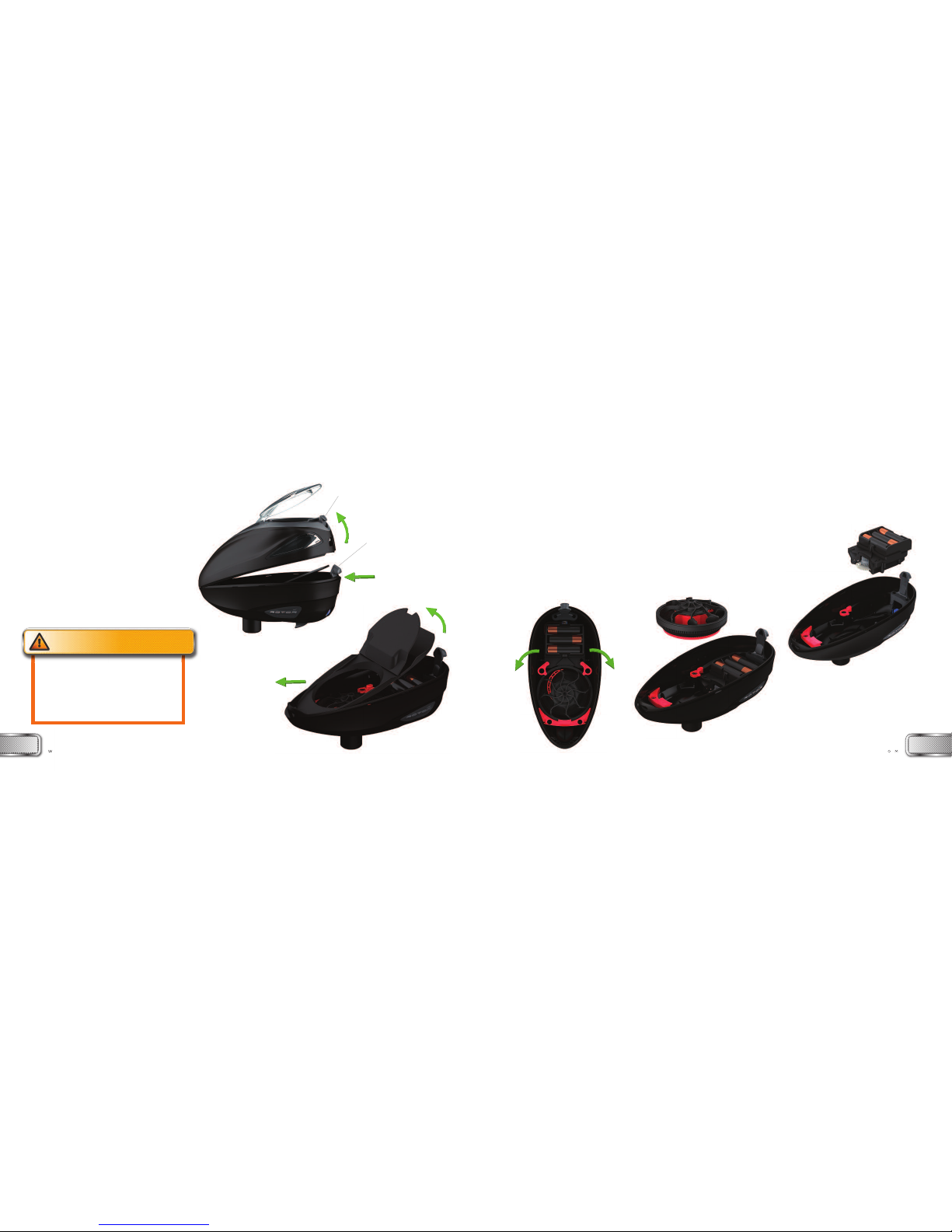
2. Check that the gearbox is inserted correctly into the bottom shell, follow instructions on page 4.
You should hear an audible click when pushing the on/off button.
3. Check that the batteries are fresh and installed the correct way. For battery installation follow instructions on page 2.
4. ake sure the wire from the battery pack to the gearbox is fully inserted into the connector.
5. Check that the Jam Release Trigger is all the way forward. If you turn the loader on but there is no spring tension pulling the Jam Release
trigger back re-insert the gearbox into the bottom shell.
OTO LOADE IS LOUD
If the Rotor Loader sounds very loud while running, please do a thorough cleaning of all parts. Dust and dirt will cause excessive sound.
OTO LOADE IS JAMMING
If you are getting paintballs jammed in the Rotor Loader please check the following steps.
1. ake sure the two red retaining tabs are turned to locked position. For instructions see page 5.
2. Check that all Rotor Loader parts are clean of any dirt and debris.
3. Install new batteries into the Rotor Loader. If you notice a significant increase in the rotating speed of the carousel, this could be the cause.
4. ake sure you are using fresh, good quality paintballs. Use of soft / wet paintballs or reballs can cause jamming.
5. With no paintballs in the Rotor Loader, pull back the Jam Release Trigger. It should have a spring tension pushing it forward.
If not, please re-insert the gearbox into the bottom shell.
6
CHANGING LID/WINDOWS
LID EPLACEMENT
1. With the top shell off (see page 2 for instructions on top shell removal) use a
philips screw driver to unscrew the five screws securing the carrier.
2. With the lid closed, push the lid axle pin partially out to either side using a
metal pin such as an allen key.
3. Open the lid and lift the side of the lid hinge arm that is no longer
retained by the cross pin (see picture 5b).
4. Slide the lid off the cross pin. Be careful not to loose the lid spring.
5. To install new lid, follow directions in reverse order.
WINDOW EPLACEMENT
1. With the top shell off (see page 2 for instructions on
top shell removal), reach inside and push firmly on the
rear upper corner of the window.
2. The rear two locking tabs will pop out.
3. Slide the window rearward and out of the top shell.
4. To install new window, follow directions in reverse
order.
Figure 5a
T OUBLESHOOTING
Figure 5b
W W W . D Y E P A I N T B A L L . C O
W A N I N G
Over filling the otor Loader with paintballs and
forcing the lid closed will cause jamming. 7

LEGAL INFO MATIONEXPLODED VIEW
W W W . R O T O R L O A D E R . C O
LIMITED WA ANTY
DYE Precision, Inc. warrants that your DYE®Rotor Loader will be free from defects in materials and
workmanship for 90 days from the date of original retail purchase. Any product determined by DYE®to
be defective in materials or workmanship in accordance with the above warranty will be repaired or
replaced, at the option of DYE®, free of charge when received at the factory freight prepaid, together with
proof of purchase. This warranty is expressly in lieu of all other warranties.
Any implied warranties of merchantability or fitness for a particular purpose are limited to the same
duration as this expressed warranty. This warranty does not cover incidental or consequential damages.
DYE®shall not be liable for any incidental or consequential damages. Some states do not allow the
exclusion or limitation of implied warranties, incidental or consequential damages, so the above
limitations and exclusions may not apply to you. This warranty does not cover any problem resulting
from misuse, abuse, neglect, alteration, failure to perform maintenance as instructed, unauthorized repair
or service, or damage caused by contaminants. This warranty does not cover any representation or
warranty made by Dealers beyond the provisions of this warranty. This warranty does not cover costs
incurred for normal repair, inspection and preventive maintenance. You must establish proof of purchase
to obtain warranty service or replacement. You may establish proof of purchase by completing the
Warranty Registration Card and mailing it to DYE®. This warranty gives you specific legal rights, and
you also have other rights which vary from state to state.
If you have any questions about your DYE®product, please call DYE Precision, Inc. at (858) 536-5183 or
visit www.dyeprecision.com.
U.S. and International Patents Pending. Rotor is a pending trademark of DYE Precision, Inc.
8W W W . D Y E P A I N T B A L L . C O
01 Top shell
02 Carrier
03 Lid
04 Lid cross pin
05 Secondary locking tab
06 Windows
07 Carrier screws (5)
08 Bottom shell
09 Gearbox / Battery tray
10 Planetary Gear Assembly
11 Rotor base
12 Center Rotor Arm
13 Upper Rotor
14 Floor tray
15 Collapsing floor plate
PA TS LIST
9
Table of contents