3-40-0012-04 Printed in USA
TESTING
One or Two Links can be used for testing. Links may be statically tested without being connected to IEDs as follows:
1. Connect the Links as described in the installation instructions steps 1, 3, 4, 5 and 6 or connect a short length of
simplex fiber cable from the T to the R receptacle of the unit to test.
2. Instead of connecting an IED for the signal and control source described is Step 2, a 9 volt battery can be
connected to the “local” Link and a dc volt meter connected to the “remote” Link. Connect the battery (-) terminal to
Pin 5 of the “local” Link and the meter (-) lead to Pin 5 of the “remote” Link or pin 5 of the local link if Loopback is
used.
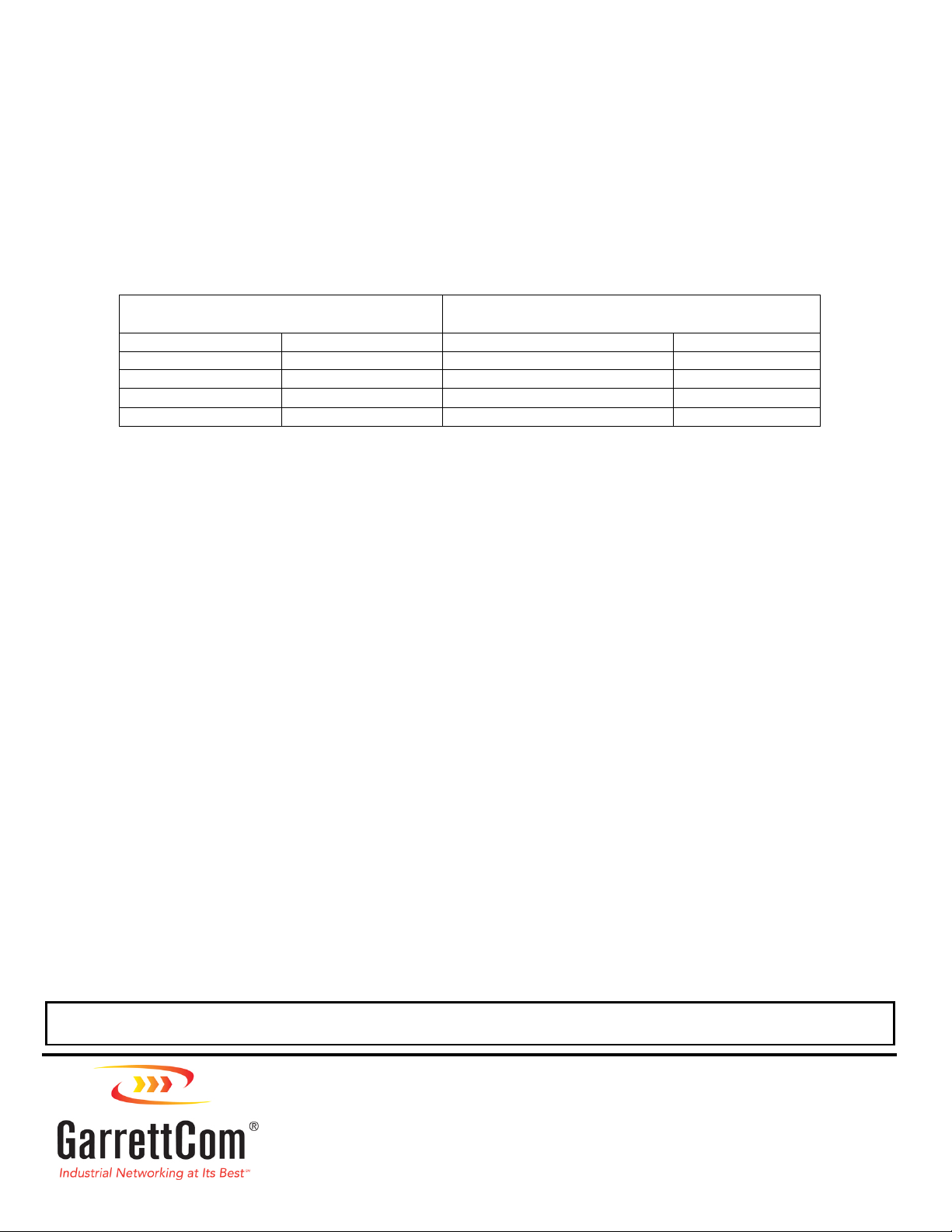
3. With the Links connected and synchronized, “SYNC” LED on steady, test per the following table:
At The Local Link At The Remote Link*
or If Loopback is used the Local Link*
Apply (+) 9 Volts to LED Illuminates Meter Reads > (+) 5 Volts on LED Illuminates
Pin 1 CH1 T Pin 6 CH1 R
Pin 2 CH2 T Pin 7 CH2 R
Pin 3 CH3 T Pin 8** CH3 R
Pin 4 CH4 T Pin 9 CH4 R
*The meter will read > (-) 5 volts until the signal is applied to the Link at the “local” end.
**If Switch 2 channel 3 is set for IRIG-B (not factory default) Pin 8 will read ~0 volts
until the signal is applied at the “local” end
4. Next, if channel 4 is not used for data, open the switch access on the top of the Link and set switch 1 to the sync
position. Then connect the meter to pin 9 of the “remote” Link. The meter should read >(+) 5 volts while the Links are
synchronized. With the meter still connected, disconnect one of the fiber leads. The “Sync’ LED turns off and the
meter reads >(-) 5 volts.
5. If two links are used for the testing, Interchange the “local” Link with the “remote” Link and re-test; following all the above
steps
Î
ÎÎ
ÎNote: Dynamic functional testing can only be achieved by using an IED connected to each Link. This allows full
communication dynamics to verify system operation including data passing, control and timing.
TROUBLESHOOTING
If the optical link does not operate properly, use the following check list:
1. Are both Links powered properly? - Are “POWER ON” LEDs illuminated?
2. Is the “SYNC” LED off? (Links are not synchronized)
• Check the FOC connections - Are both fibers connected “T” to “R” - not “T” to “T” nor “R” to “R”?
• Are both Fibers the same length (within a meter)?
• Check FOC and terminations for continuity
• Consult factory
3. Is the “SYNC” LED on steady? (Links are synchronized)
• Check the Channel “T” LEDs of the local Link - are they illuminated?
• NO - Re-check connections to IED for function and signal direction (Input Vs Output)
• YES - Are the corresponding Channel “R” LEDs of the remote Link illuminated?
• NO - Consult factory
• YES - Re-check connections to IED for function and signal direction (Input Vs Output)
4. Are the IEDs set at the same baud rate?
5. Are all the IEDs logic and control functions satisfied? - Check IED’s “Description Of Operation”
6. Consult Factory - Please have the IED instruction book available along with your connection diagram to the Link.
DO NOT ATTEMPT TO DISASSEMBLE LINKS AS THERE ARE NO SERVICEABLE PARTS WITHIN.
THIS ACTION WILL VOID THE WARRANTY.
25 Commerce Way #1 North Andover, MA 01845
Phone 978-688-8807 •Fax 978-688-8771
IS5941D4 •Rev AD
www.garrettcom.com


